Fiber Optic Communication System Design Considerations
When designing a fiber optic communication system some of the following factors must be taken into consideration:
Which modulation and multiplexing technique is best suited for the particular application?
Is enough power available at the receiver (power budget)?
Rise-time and bandwidth characteristics
Noise effects on system bandwidth, data rate, and bit error rate
Are erbium-doped fiber amplifiers required?
What type of fiber is best suited for the application?
Cost
Power Budget
The power arriving at the detector must be sufficient to allow clean detection with few errors. Clearly, the signal at the receiver must be larger than the noise. The power at the detector, Pr, must be above the threshold level or receiver sensitivity Ps.
Pr >= Ps
The receiver sensitivity Ps is the signal power, in dBm, at the receiver that results in a particular bit error rate (BER). Typically the BER is chosen to be one error in 109 bits or 10–9.
The received power at the detector is a function of:
Power emanating from the light source (laser diode or LED)—(PL)
Source to fiber loss (Lsf)
Fiber loss per km (FL) for a length of fiber (L)
Connector or splice losses (Lconn)
Fiber to detector loss (Lfd)
The allocation of power loss among system components is the power budget. The power margin is the difference between the received power Pr and the receiver sensitivity Ps by some margin Lm.
Lm = Pr – Ps
where Lm is the loss margin in dB, Pr is the received power, Ps is the receiver sensitivity in dBm.
If all of the loss mechanisms in the system are taken into consideration, the loss margin can be expressed as the following equation. All units are dB and dBm.
Lm = PL – Lsf – (FL × L) – Lconn – Lfd – Ps
Bandwidth and Riser Time Budgets
The transmission data rate of a digital fiber optic communication system is limited by the rise time of the various components, such as amplifiers and LEDs, and the dispersion of the fiber. The cumulative effect of all the components should not limit the bandwidth of the system. The rise time tr and bandwidth BW are related by
BW = 0.35/tr
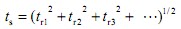
This equation is used to determine the required system rise time. The appropriate components are then selected to meet the system rise time requirements. The relationship between total system rise time and component rise time is given by the following equation
where ts is the total system rise time and tr1, tr2, … are the rise times associated with the various components.
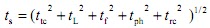
To simplify matters, divide the system into five groups:
Transmitting circuits (ttc)
LED or laser (tL)
Fiber dispersion (tf)
Photodiode (tph)
Receiver circuits (trc)
The system rise time can then be expressed as
The system bandwidth can then be calculated using the following equation from the total rise time ts as given in the above equation
BW = 0.35/ts
Electrical and Optical Bandwidth
Electrical bandwidth (BWel) is defined as the frequency at which the ratio current out/current in (Iout/Iin) drops to 0.707. (Analog systems are usually specified in terms of electrical bandwidth.)
Optical bandwidth (BWopt) is the frequency at which the ratio power out/power in (Pout/Pin) drops to 0.5.
Because Pin and Pout are directly proportional to Iin and Iout (not I2in and I2out), the half-power point is equivalent to the half-current point. This results in a BWopt that is larger than the BWel as given in the following equation
BWel = 0.707 × BWopt
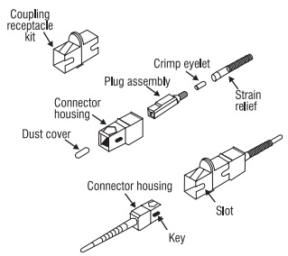
Fiber Connectors
Many types of connectors are available for fiber optics, depending on the application. The most popular are:
SC—snap-in single-fiber connector
ST and FC—twist-on single-fiber connector
FDDI—fiber distributed data interface connector
In the 1980s, there were many different types and manufacturers of connectors. Today, the industry has shifted to standardized connector types, with details specified by organizations such as the Telecommunications Industry Association(TIA), the International Electrotechnical Commission, and the Electronic Industry Association (EIA).
Snap-in connector (SC)—developed by Nippon Telegraph and Telephone of Japan. Like most fiber connectors, it is built around a cylindrical ferrule that holds the fiber, and it mates with an interconnection adapter or coupling receptacle. A push on the connector latches it into place, with no need to turn it in a tight space, so a simple tug will not unplug it. It has a square cross section that allows high packing density on patch panels and makes it easy to package in a polarized duplex form that ensures the fibers are matched to the proper fibers in the mated connector.
Twist-on single-fiber connectors (ST and FC)—long used in data communication; one of several fiber connectors that evolved from designs originally used for copper coaxial cables.
Duplex connectors—A duplex connector includes a pair of fibers and generally has an internal key so it can be mated in only one orientation. Polarizing the connector in this way is important because most systems use separate fibers to carry signals in each direction, so it matters which fibers are connected. One simple type of duplex connector is a pair of SC connectors, mounted side by side in a single case. This takes advantage of their plug-in-lock design.
Continue Reading This Article
Sign in with a free account to unlock the full article and access the complete MapYourTech knowledge base.
Other duplex connectors have been developed for specific types of networks, as part of comprehensive standards. One example is the fixed-shroud duplex (FSD) connector specified by the fiber distributed data interface (FDDI) standard.
Fiber Optic Couplers
A fiber optic coupler is a device used to connect a single (or multiple) fiber to many other separate fibers. There are two general categories of couplers:
Star couplers
T-couplers
Star Couplers
Transmissive type
Optical signals sent into a mixing block are available at all output fibers. Power is distributed evenly. For an n × n star coupler (n-inputs and n-outputs), the power available at each output fiber is 1/n the power of any input fiber.
The output power from a star coupler is simply
Po = Pin/n
where n = number of output fibers.
An important characteristic of transmissive star couplers is cross talk or the amount of input information coupled into another input. Cross coupling is given in decibels and is typically greater than 40 dB.
The reflective star coupler has the same power division as the transmissive type, but cross talk is not an issue because power from any fiber is distributed to all others.
T-Couplers
In the following figure, power is launched into port 1 and is split between ports 2 and 3. The power split does not have to be equal. The power division is given in decibels or in percent. For example, and 80/20 split means 80% to port 2, 20% to port 3. In decibels, this corresponds to 0.97 dB for port 2 and 6.9 dB for port 3.
Directivity describes the transmission between the ports. For example, if P3/P1 = 0.5, P3/P2 does not necessarily equal 0.5. For a highly directive T-coupler, P3/P2 is very small. Typically, no power is expected to be transferred between any two ports on the same side of the coupler.
Another type of T-coupler uses a graded-index (GRIN) lens and a partially reflective surface to accomplish the coupling. The power division is a function of the reflecting mirror. This coupler is often used to monitor optical power in a fiber optic line.
Wavelength-Division Multiplexers (WDM)
The couplers used for wavelength-division multiplexing (WDM) are designed specifically to make the coupling between ports a function of wavelength. The purpose of these couplers is to separate (or combine) signals transmitted at different wavelengths. Essentially, the transmitting coupler is a mixer and the receiving coupler is a wavelength filter. Wavelength-division multiplexers use several methods to separate different wavelengths depending on the spacing between the wavelengths. Separation of 1310 nm and 1550 nm is a simple operation and can be achieved with WDMs using bulk optical diffraction gratings. Wavelengths in the 1550-nm range that are spaced at greater than 1 to 2 nm can be resolved using WDMs that incorporate interference filters. An example of an 8-channel WDM using interference filters is given in the following figure. Fiber Bragg gratings are typically used to separate very closely spaced wavelengths in a DWDM system (< 0.8 nm).
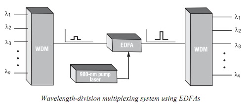
Erbium-Doped Fiber Amplifiers (EDFA)
Erbium-doped fiber amplifiers (EDFA)—The EDFA is an optical amplifier used to boost the signal level in the 1530-nm to 1570-nm region of the spectrum. When it is pumped by an external laser source of either 980 nm or 1480 nm, signal gain can be as high as 30 dB (1000 times). Because EDFAs allow signals to be regenerated without having to be converted back to electrical signals, systems are faster and more reliable. When used in conjunction with wavelength-division multiplexing, fiber optic systems can transmit enormous amounts of information over long distances with very high reliability.
Fiber Bragg Gratings (FBG)
Fiber Bragg gratings—Fiber Bragg gratings are devices that are used for separating wavelengths through diffraction, similar to a diffraction grating (see the following figure). They are of critical importance in DWDM systems in which multiple closely spaced wavelengths require separation. Light entering the fiber Bragg grating is diffracted by the induced period variations in the index of refraction. By spacing the periodic variations at multiples of the half-wavelength of the desired signal, each variation reflects light with a 360° phase shift causing a constructive interference of a very specific wavelength while allowing others to pass. Fiber Bragg gratings are available with bandwidths ranging from 0.05 nm to >20 nm.
Fiber Bragg grating are typically used in conjunction with circulators, which are used to drop single or multiple narrowband WDM channels and to pass other “express” channels. Fiber Bragg
gratings have emerged as a major factor, along with EDFAs, in increasing the capacity of next generation high-bandwidth fiber optic systems.
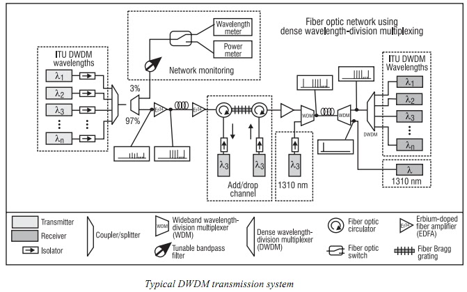
The following figure depicts a typical scenario in which DWDM and EDFA technology is used to transmit a number of different channels of high-bandwidth information over a single fiber. As shown, n-individual wavelengths of light operating in accordance with the ITU grid are multiplexed together using a multichannel coupler/splitter or wavelength-division multiplexer. An optical isolator is used with each optical source to minimize troublesome back reflections. A tap coupler then removes 3% of the transmitted signal for wavelength and power monitoring. Upon traveling through a substantial length of fiber (50-100 Km), an EDFA is used to boost the signal strength. After a couple of stages of amplifications, an add/drop channel consisting of a fiber Bragg grating and circulator is introduced to extract and then reinject the signal operating at the λ3 wavelength. After another stage of amplification via EDFA, a broadband WDM is used to combine a 1310-nm signal with the 1550-nm window signals. At the receiver end, another broadband WDM extracts the 1310-nm signal, leaving the 1550-nm window signals. The 1550-nm window signals are finally separated using a DWDM that employs an array of fiber Bragg gratings, each tuned to the specific transmission wavelength. This system represents the current state of the art in high-bandwidth fiber optic data transmission.
Optical networking engineer with nearly two decades of experience across DWDM, OTN, coherent optics, submarine systems, and cloud infrastructure. Founder of MapYourTech.
Read full bio →
Everything you enjoy here — now fits right in your pocket. Whether you're on the commute, waiting at the lab, or unwinding on the couch — keep learning on the go.