29 min read

OTN Clock and Synchronization
Comprehensive Guide to Timing, Jitter Control, and Synchronization in Optical Transport Networks
1 Introduction
In the realm of optical transport networks, clock and synchronization systems form the invisible backbone that ensures accurate, reliable data transmission across vast distances and complex network topologies. Unlike traditional synchronous systems such as SONET/SDH that require strict clock alignment across all network elements, OTN employs a sophisticated asynchronous architecture with multiple clock domain types, each serving specific purposes in the network hierarchy.
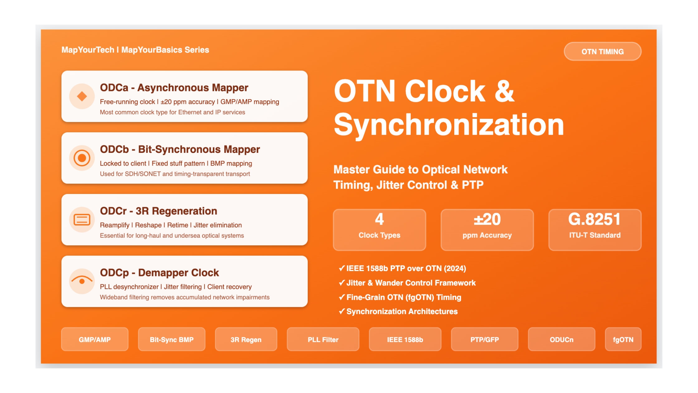
The control of jitter and wander within OTN represents one of the most critical aspects of network performance. As signals traverse through mappers, multiplexers, regenerators, and demappers, timing variations accumulate. Without proper clock management and jitter control mechanisms, these accumulated variations can lead to bit errors, frame slips, and service degradation. ITU-T Recommendation G.8251 establishes the framework for controlling these timing impairments, defining four distinct ODU clock (ODC) types and their associated requirements.
The evolution of OTN timing has accelerated significantly in recent years. The 2024 introduction of IEEE 1588b standard brought Precision Time Protocol (PTP) capabilities to OTN, enabling time synchronization through optical transport layers using Generic Framing Procedure (GFP) encapsulation. This development, combined with fine-grain OTN (fgOTN) specifications for sub-1G services, represents a fundamental shift in how modern networks handle timing distribution and synchronization.
OTN Clock and Synchronization System Overview
Interactive visualization showing the complete OTN timing architecture with clock domains and signal flows
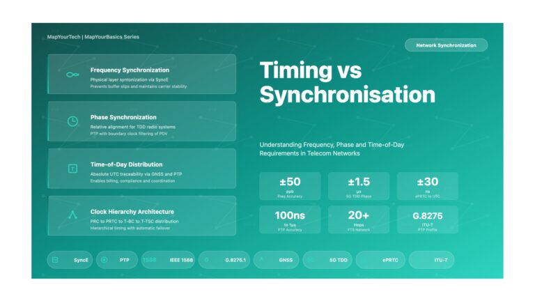
Key Timing Concepts in OTN
Asynchronous Operation: Unlike SONET/SDH, OTN does not require network-wide clock synchronization. Each network element can operate with independent clock sources, using stuffing bytes to accommodate rate differences.
ODU Clock (ODC) Types: Four distinct clock types serve different purposes - ODCa for async mapping, ODCb for bit-synchronous mapping, ODCr for 3R regeneration, and ODCp for client recovery with jitter filtering.
Frequency Accuracy: Most OTN clocks maintain ±20 ppm accuracy (traceable to ITU-T G.811), with exceptions for Ethernet and some high-speed clients requiring ±100 ppm tolerance.
Jitter and Wander Control: ITU-T G.8251 defines comprehensive requirements for jitter generation, transfer, and tolerance to ensure client signals remain within acceptable quality parameters through extensive network traversals.
The Critical Need for Clock Management
The importance of proper clock and synchronization management in OTN cannot be overstated. Consider a typical intercontinental network path where a 10 Gigabit Ethernet client signal traverses multiple OTN islands, each containing mappers, optical multiplexers, regenerators, and switching nodes. At each network element, timing variations are introduced through clock recovery circuits, digital signal processing, and buffering mechanisms. Without carefully designed clock filtering and jitter attenuation:
- Timing Jitter Accumulation: High-frequency phase variations accumulate, potentially exceeding the timing tolerance of receiving equipment and causing bit errors or frame synchronization loss
- Wander Buildup: Low-frequency phase variations grow over multi-hop paths, leading to buffer overflows, frame slips, and service interruptions in client applications
- Interoperability Issues: Equipment from different vendors must maintain consistent timing behavior to ensure seamless multi-vendor network operation
- Quality of Service Degradation: Timing impairments directly impact metrics such as bit error rate, availability, and latency variation that define service quality
The OTN clock architecture addresses these challenges through a multi-layered approach. At the physical layer, clock recovery circuits extract timing from incoming optical signals. At the ODU layer, different clock types provide appropriate timing for mapping, multiplexing, and demapping operations. Sophisticated phase-locked loops (PLLs) with carefully specified bandwidth and jitter transfer characteristics filter accumulated impairments. Buffer management strategies accommodate frequency offsets while preventing overflow or underflow conditions.
2 Historical Context and Evolution
From Synchronous to Asynchronous: The OTN Revolution
The evolution of timing and synchronization in optical networks represents a fundamental shift in architectural philosophy. Traditional SONET/SDH networks, dominant throughout the 1990s and early 2000s, relied on hierarchical synchronization where every network element traced its timing back to a Primary Reference Clock (PRC) conforming to ITU-T G.811. This synchronous operation, while providing deterministic timing behavior, imposed significant operational complexity and infrastructure requirements.
The introduction of OTN by ITU-T in 2001 (first edition of G.709) marked a paradigm shift. OTN was designed from the ground up to support asynchronous operation, where client signals could be mapped into ODU containers without requiring network-wide synchronization. This flexibility came with new technical challenges in managing timing variations across asynchronous boundaries, leading to the development of the comprehensive jitter and wander control framework in ITU-T G.8251.
OTN Introduction: ITU-T G.709 first edition defines OTUk frame structure with asynchronous mapping capability, breaking from SONET/SDH synchronous paradigm. Initial focus on 2.5G, 10G, and 40G rates.
Jitter/Wander Framework: ITU-T G.8251 establishes comprehensive timing requirements. ODC types (ODCa, ODCb, ODCr) defined with specific jitter generation and transfer specifications.
100G Era: Introduction of ODU4 and OTU4 for 100 Gigabit services. Generic Mapping Procedure (GMP) standardized for flexible client mapping with improved jitter performance. ODCp demapper requirements refined.
Flexible OTN: ODUflex and ODUCn specifications enable flexible bandwidth allocation beyond fixed hierarchies. Beyond-100G rates (200G, 400G) supported through FlexO technology.
High-Speed Ethernet Integration: Support for 200GE, 400GE clients with appropriate timing tolerances. G.8251 updated to address timing requirements for these high-rate services and ODUCn containers.
Latest G.8251 Revision: November 2022 edition consolidates timing requirements across all OTN rates including ODUCn. Comprehensive jitter and wander specifications for modern high-capacity networks.
IEEE 1588b PTP over OTN: Major milestone enabling Precision Time Protocol transport through OTN using GFP encapsulation. Opens new applications beyond traditional telecom timing distribution.
Fine-Grain OTN (fgOTN): ITU-T G.709.20 defines sub-1G granularity services with dedicated timing specifications in G.8251 Annex A. Addresses metro/access network requirements for efficient small-bandwidth transport.
Evolution of OTN Timing Standards and Technologies
Timeline showing major developments in OTN clock and synchronization from 2001 to 2025
Recent Developments (2024-2025)
The year 2024 marked a watershed moment in OTN timing with the ratification of IEEE 1588b, introducing standardized Precision Time Protocol (PTP) transport over optical networks. This development addresses growing demands for precise time synchronization in applications ranging from 5G mobile backhaul to financial trading networks and distributed sensing systems. Unlike traditional synchronization distribution through dedicated Synchronization Status Messages (SSM), PTP over OTN enables sub-microsecond accuracy through direct protocol encapsulation.
IEEE 1588b: PTP over OTN (2024)
The new standard defines PTP message encapsulation using Generic Framing Procedure (GFP) instead of Ethernet or IP. PTP messages are mapped into the OTN Synchronization Message Channel (OSMC), a 128-bit field allocated in the OTN overhead across multi-frames. This approach enables:
- Time synchronization distribution through OTN physical layer without requiring packet network overlay
- Boundary clock and hybrid clock modes supporting IEEE 1588v2 requirements
- Compensation for link delay asymmetry introduced by different wavelengths in bidirectional transmission
- Integration with existing ITU-T synchronization reference chains (G.803, G.811)
Simultaneously, the introduction of fine-grain OTN (fgOTN) in ITU-T G.709.20 addresses the inefficiency of transporting sub-1G services in traditional OTN containers. With minimum ODU0 capacity at 1.25 Gbps, legacy systems waste significant bandwidth for lower-rate private line services like E1, T1, STM-1, and sub-1G Ethernet. The fgOTN specification defines ODUflex containers with approximately 10 Mbps granularity, enabling efficient metro and access network deployments. Dedicated synchronization requirements for fgOTN appear in ITU-T G.8251 Annex A, ensuring proper timing behavior for these smaller bandwidth allocations.
The optical transport market continues robust growth, reaching $27 billion in 2025 with projections of $40.44 billion by 2030 (8.42% CAGR). This expansion drives by hyperscaler investments in data center interconnection, widespread 400ZR/ZR+ coherent pluggable adoption, and government-funded fiber rollouts. From a timing perspective, these developments create new challenges and opportunities. Distributed OTN architectures are replacing centralized switching fabrics, requiring more sophisticated distributed timing solutions. The convergence of IP and optical layers through coherent pluggables demands careful consideration of how timing domains interact at network boundaries.
3 Core Concepts and Fundamentals
Understanding ODU Clock (ODC) Types
The ODU clock architecture represents the heart of OTN timing management. Unlike monolithic clock systems where a single oscillator drives all timing functions, OTN employs four specialized clock types, each optimized for specific network functions. This modular approach enables the asynchronous operation that distinguishes OTN from its synchronous predecessors while maintaining precise timing control where needed.
The term "clock" in ODU clock (ODC) refers not merely to a frequency source, but to a complete clock filtering and generating circuit incorporating frequency generation, phase-locked loops, jitter filtering, and buffer management. Each ODC type includes specific atomic functions defined in ITU-T G.798, representing the fundamental building blocks of OTN equipment behavior.
Four ODC Types: Functional Comparison
Interactive diagram showing the distinct roles and characteristics of ODCa, ODCb, ODCr, and ODCp
ODCa: The Asynchronous Mapper Clock
The ODCa represents the most widely deployed clock type in OTN networks, enabling the asynchronous operation that fundamentally distinguishes OTN from synchronous predecessors. Operating as a free-running oscillator with ±20 ppm frequency accuracy (referenced to an ITU-T G.811 primary reference clock), the ODCa generates timing for mapping client signals into ODUk containers without requiring synchronization to the client clock.
This independence proves particularly valuable for modern packet-based clients like Ethernet, where timing accuracy requirements are relaxed compared to TDM services. When an Ethernet frame arrives at the OTN mapper, the ODCa provides a stable, accurate clock for ODUk frame generation. Rate differences between the incoming client and the ODUk container are accommodated through Generic Mapping Procedure (GMP) or Asynchronous Mapping Procedure (AMP), which use justification bytes in the OPU overhead to dynamically adjust for frequency offsets.
ODCa Frequency Accuracy Specification
Under free-running conditions, the ODCa output frequency must maintain the following accuracy:
f_ODCa = f_nominal ± Δf_max

Where:
  f_ODCa     = Actual ODCa output frequency
  f_nominal  = Nominal ODUk rate (e.g., 2.498775040 Gbps for ODU1)
  Δf_max     = Maximum frequency offset = ±20 ppm

For ODU2 (10.037273924 Gbps):
  Δf_max = 10.037273924 Gbps × 20 × 10-6
         = ±200.745 kHz
         = ±200,745 bits/second

Reference: ITU-T G.8251 Clause A.3
The ODCa architecture typically employs a temperature-compensated crystal oscillator (TCXO) or oven-controlled crystal oscillator (OCXO) as the frequency reference, combined with digital frequency synthesis to generate the precise ODUk rates. Modern implementations use fractional-N PLLs that can synthesize any required ODUk rate from a common reference, enabling multi-rate support in a single device. The free-running nature means the ODCa continues generating valid ODUk frames even when client signals fail, producing Alarm Indication Signal (AIS) or Open Connection Indication (OCI) with proper timing characteristics.
ODCb: The Bit-Synchronous Mapper Clock
The ODCb takes a fundamentally different approach, locking its output frequency to the incoming client signal clock through a phase-locked loop. This bit-synchronous operation proves essential for SDH/SONET clients and situations where maintaining the client timing relationship is critical for network synchronization distribution. When an STM-N signal enters the ODCb mapper, the clock recovery circuit extracts timing from the incoming data stream, and the ODCb PLL locks to this recovered clock.
Bit-synchronous mapping offers distinct advantages for timing transparency. Since the ODUk frame rate tracks the client rate, any frequency variations in the client propagate through the OTN layer. This proves crucial when SDH signals carry network synchronization - the timing information must traverse the OTN island without degradation. However, this tight coupling also means the ODCb must handle client signal failures gracefully, entering free-run mode and generating AIS when the input is lost.
The frequency accuracy requirement for ODCb depends on the client type. For ODUk signals themselves, ±20 ppm applies. For 10GE, 25GE, 200GE, 400GE, and various Fibre Channel rates, ±100 ppm tolerance accommodates the Ethernet physical layer specifications. For SBCON (IBM mainframe connectivity), the requirement relaxes to ±200 ppm. When transitioning between locked and free-run states, ITU-T G.8251 specifies that initial frequency steps must not exceed 9 ppm, with subsequent drift rates below 200 ppm/second, preventing abrupt timing changes that could disrupt downstream equipment.
ODCr: The 3R Regeneration Clock
The ODCr serves a specialized but critical role in 3R (Reamplify, Reshape, Retime) regenerators that extend optical reach by completely regenerating the OTUk signal. Unlike optical amplifiers that simply boost signal power, 3R regenerators perform full electrical regeneration: reamplifying to restore signal levels, reshaping to clean up waveform distortions, and retiming to eliminate accumulated jitter. The ODCr provides the retiming function, recovering clock from the incoming degraded OTUk signal and using it to generate a clean OTUk output.
The ODCr architecture must handle significant input degradation. After hundreds of kilometers of fiber transmission through multiple optical amplifiers, the received OTUk signal may exhibit poor signal-to-noise ratio, chromatic dispersion effects, and substantial jitter accumulation. The clock recovery circuit must lock reliably despite these impairments, extracting a clean timing reference from the degraded signal. The recovered clock then drives the output circuitry, regenerating the OTUk frame with fresh timing that eliminates accumulated jitter.
3R Regeneration with ODCr Clock Recovery
Visualization of signal degradation and regeneration process with clock recovery
Like the ODCb, the ODCr must handle signal loss scenarios. When the incoming OTUk signal fails (loss of signal, loss of frame), the ODCr enters free-run mode, maintaining its output frequency within ±20 ppm accuracy. This free-run capability ensures that downstream equipment continues receiving valid timing even during upstream failures. The ODCr typically employs holdover mechanisms that maintain the last known good frequency when entering free-run, minimizing frequency steps that could disrupt network synchronization chains.
ODCp: The Demapper and Desynchronizer Clock
The ODCp represents perhaps the most sophisticated of the four clock types, responsible for the critical function of recovering clean client signals from ODUk containers while filtering accumulated jitter and wander. When an ODUk signal arrives at a demapper after traversing multiple network hops - each introducing timing variations through mappers, multiplexers, regenerators, and fiber propagation - the ODCp must extract the original client timing while removing these accumulated impairments.
The ODCp architecture centers on a wideband phase-locked loop combined with sophisticated filtering. For GMP and AMP mapped clients, the ODCp PLL locks to the "gapped" clock - the timing signal that results from extracting payload bytes and applying justification control bytes from the OPU overhead. This gapped clock reflects the client rate embedded within the ODUk container. The PLL bandwidth and transfer function are carefully specified in ITU-T G.8251 to provide appropriate jitter filtering while maintaining acceptable wander performance.
ODCp Jitter Transfer Function Requirements
The ODCp must implement a jitter transfer function that attenuates high-frequency jitter while passing lower-frequency wander components:
H(f) = |Jitter_output / Jitter_input|

For a second-order PLL:

H(f) = |2ζω_n s + ω_n²| / |s² + 2ζω_n s + ω_n²|

Where:
  f      = Jitter frequency (Hz)
  s      = j2πf (Laplace variable)
  ζ      = Damping factor (typically 0.707 for Butterworth)
  ω_n    = Natural frequency = 2πf_3dB
  f_3dB  = 3dB bandwidth

Key ODCp Bandwidth Requirements (G.8251):
  For STM-1/STM-4 into ODU0: f_3dB = 300 Hz (±30%)
  For STM-16 into ODU1:      f_3dB = 1 kHz (±30%)
  For STM-64 into ODU2:      f_3dB = 4 kHz (±30%)

At high frequencies (f >> f_3dB):
  H(f) ≈ (f_3dB / f)² = 40 dB/decade attenuation

This ensures jitter at frequencies above the PLL bandwidth
is significantly attenuated (filtered out).
The ODCp must handle multiple challenging scenarios. When mapping GMP-mapped Ethernet clients, the justification overhead introduces a sawtooth phase pattern that the ODCp must smooth out. For STM-16 mapped into ODU1 using GMP, the 272-byte overhead gap repeats every quarter OTU1 frame (12.243 microseconds), creating a 2176 UI sawtooth with 81.68 kHz frequency. Without proper filtering, this would generate excessive jitter. ITU-T G.8251 Appendix V analyzes this scenario in detail, showing that a third-order low-pass filter with approximately 8.2 kHz bandwidth reduces the sawtooth-induced jitter from 8 UI peak-to-peak to acceptable levels below 1 UI.
4 Jitter and Wander Control Framework
Understanding Jitter and Wander
Jitter and wander represent short-term and long-term timing variations respectively, distinguished by their frequency content. ITU-T defines jitter as phase variations with frequencies above 10 Hz, while wander encompasses lower-frequency variations below 10 Hz. This distinction proves critical because different mechanisms cause and propagate these timing impairments, requiring different control strategies.
High-frequency jitter typically originates from clock recovery circuits, digital signal processing, and electromagnetic interference. In OTN networks, the mapping and multiplexing processes introduce jitter through buffer delays and frame alignment operations. The sawtooth pattern from GMP mapping, discussed in the ODCp section, exemplifies mapper-induced jitter. Clock recovery circuits in regenerators contribute jitter through PLL imperfections and phase detector noise.
Wander accumulates through different mechanisms. Temperature variations affect crystal oscillator frequencies over minutes and hours. Equipment free-run conditions during synchronization reference failures introduce wander as clocks drift from their nominal frequencies. Long OTN paths spanning continents accumulate wander through the cascaded timing circuits of numerous network elements. While individual contributions may be small, the cumulative effect over 50+ hops can approach or exceed network limits.
Jitter and Wander: Frequency Domain Characteristics
Visualization showing the distinction between jitter (>10 Hz) and wander (<10 Hz) with typical sources
Network Limits and Equipment Requirements
ITU-T G.8251 establishes a hierarchical framework for jitter and wander control, defining three key specification types that work together to ensure end-to-end timing performance. Network limits specify the maximum jitter or wander acceptable at OTN network-node interfaces. Equipment output specifications define what individual network elements must achieve at their outputs. Equipment input tolerance requirements specify the minimum impairments that equipment must withstand without malfunction. This three-tier approach ensures that equipment meeting the specifications can be deployed in any combination while maintaining overall network performance within limits.
| OTU Rate | Wideband Jitter Network Limit | High-Band Jitter Network Limit | Measurement Filter |
|---|---|---|---|
| OTU1 (2.666 Gbps) | 1.5 UIpp | 0.15 UIpp | f1=10Hz, f3=20kHz, f4=40MHz |
| OTU2 (10.709 Gbps) | 1.5 UIpp | 0.15 UIpp | f1=10Hz, f3=20kHz, f4=80MHz |
| OTU3 (43.018 Gbps) | 1.5 UIpp | 0.15 UIpp | f1=10Hz, f3=100kHz, f4=320MHz |
| OTU4 (111.810 Gbps) | 1.5 UIpp | 0.15 UIpp | f1=10Hz, f3=100kHz, f4=840MHz |
| ODU0 (1.244 Gbps) | 1.5 UIpp | 0.1 UIpp | f1=10Hz, f3=18kHz, f4=20MHz |
Equipment jitter generation specifications prove more stringent than network limits, providing margin for jitter accumulation through cascaded network elements. For example, OTU2 equipment output jitter must not exceed 0.1 UIpp wideband and 0.075 UIpp high-band - significantly tighter than the 1.5/0.15 UIpp network limits. This ensures that even after traversing many network hops, accumulated jitter remains within network limits.
Jitter tolerance specifications define the minimum impairments that equipment must withstand without errors. An OTU2 interface must tolerate 1.5 UIpp wideband jitter and 0.15 UIpp high-band jitter at its input while maintaining error-free operation. Additionally, equipment must tolerate sinusoidal jitter at specific frequencies - for OTU2, tolerance extends to 15 UIpp at 100 Hz, decreasing to 0.15 UIpp at 10 MHz. These sinusoidal specifications ensure equipment can handle resonant jitter peaks that may occur in network PLL chains.
5 Synchronization Architecture and PTP over OTN
Traditional OTN Synchronization Distribution
While OTN physical layers operate asynchronously without requiring network-wide synchronization, many deployments distribute timing reference signals through OTN networks to support synchronous clients and time-sensitive applications. Traditional synchronization distribution in OTN networks employs Synchronization Status Messages (SSM) carried in the ODU overhead, combined with external synchronization reference inputs at OTN network elements.
The ITU-T G.803 synchronization reference chain model, originally developed for SDH networks, extends to OTN deployments. This hierarchical architecture begins with Primary Reference Clocks (PRCs) traceable to atomic standards or GPS, distributing timing through Synchronization Supply Units (SSUs) and ultimately to network equipment slave clocks. When OTN islands appear in this chain, they effectively replace SDH equipment slaves (SECs) while maintaining overall synchronization chain integrity.
Traditional Synchronization Distribution Through OTN
Hierarchical timing distribution showing PRC, SSU, and OTN network elements
IEEE 1588b: Precision Time Protocol over OTN
The ratification of IEEE 1588b in 2024 represents a transformative development for OTN timing distribution, enabling Precision Time Protocol (PTP) transport directly through optical transport networks. Unlike traditional frequency synchronization using SSM, PTP provides both frequency and phase/time synchronization with sub-microsecond accuracy - critical for 5G mobile fronthaul, financial trading networks, power grid substations, and distributed sensor arrays.
The key innovation in IEEE 1588b lies in its mapping of PTP messages into the OTN Synchronization Message Channel (OSMC), a 128-bit field allocated across the eight frames of an OTN multi-frame. Instead of encapsulating PTP in Ethernet or IP packets (the traditional approach), IEEE 1588b defines Generic Framing Procedure (GFP) encapsulation of PTP messages, which are then inserted into the OSMC overhead bytes (columns 27 and 28 of the OTU overhead). This native OTN transport offers approximately 2.56 Mbps bandwidth per 100G interface - sufficient for PTP event messages and follow-up messages with minimal latency.
PTP over OTN Key Benefits
Direct Physical Layer Transport: PTP messages travel in OTN overhead without requiring packet network overlay, reducing latency and complexity compared to packet-based PTP distribution.
Asymmetry Compensation: The standard addresses link delay asymmetry caused by bidirectional transmission over different wavelengths (common in DWDM systems), providing calibration mechanisms for accurate time transfer.
Boundary and Hybrid Clocks: OTN network elements can function as PTP boundary clocks (regenerating PTP messages) or hybrid clocks (combining boundary clock and transparent clock functions), enabling scalable multi-hop time distribution.
Integration with Existing Infrastructure: Works alongside traditional SSM-based frequency synchronization, allowing mixed deployments and gradual migration to phase/time synchronization where needed.
IEEE 1588b PTP Transport Through OTN (2024 Standard)
Visualization of PTP message flow through OTN network with boundary clocks and GFP encapsulation
Implementation of PTP over OTN requires careful attention to timestamping accuracy and asymmetry compensation. Event messages (Sync, Delay_Req) must be timestamped at the exact moment they cross the OTN physical layer boundary - typically at the output of the optical transmitter or input of the optical receiver. Hardware timestamping with nanosecond resolution is essential. The challenge intensifies in DWDM systems where transmit and receive paths use different wavelengths, each experiencing different chromatic dispersion and propagation delays through the fiber. IEEE 1588b provides the mathematical framework for calculating and compensating these asymmetries based on wavelength, fiber type, and span length.
Fine-Grain OTN (fgOTN) Synchronization
The 2024-2025 introduction of fine-grain OTN (fgOTN) in ITU-T G.709.20 addresses a long-standing gap in OTN efficiency for sub-1G services. Traditional OTN's minimum container of ODU0 at 1.244 Gbps proves wasteful for lower-rate services like E1 (2.048 Mbps), T1 (1.544 Mbps), STM-1 (155 Mbps), or sub-1G Ethernet. The fgOTN specification defines flexible ODUflex containers with approximately 10 Mbps granularity, enabling efficient transport of these small-bandwidth services in metro and access networks.
From a synchronization perspective, fgOTN introduces new considerations documented in ITU-T G.8251 Annex A. The smaller payload sizes and different frame structures require adjusted timing specifications. While maintaining the fundamental ODC architecture (ODCa for async mapping, ODCb for bit-sync, ODCp for demapping), the jitter and wander generation specifications are tailored to fgOTN's operational characteristics. For example, the reduced overhead processing in fgOTN frames affects jitter transfer functions and buffer sizing requirements in the ODCp desynchronizer.
6 Practical Implementation and Case Studies
Network Deployment Scenarios
Real-world OTN deployments exhibit diverse timing architectures based on network scale, client requirements, and synchronization needs. A long-haul intercontinental network carrying primarily IP/Ethernet traffic may employ asynchronous ODCa mapping throughout, with no external synchronization distribution. Conversely, a metro network serving mobile backhaul must implement comprehensive synchronization chains to meet 5G timing requirements. Understanding these deployment patterns proves essential for proper network planning and timing design.
Scenario 1: Long-Haul IP/DWDM
Application: Transcontinental router interconnection with 400G coherent interfaces
Timing Architecture:
- ODCa async mapping for all services
- No external sync distribution
- 3R regeneration every 500-800 km with ODCr
- ±20 ppm frequency accuracy sufficient
Design Considerations: Focus on jitter tolerance for long cascades; ODCp bandwidth optimization for multi-hop paths
Scenario 2: Metro Mobile Backhaul
Application: 5G base station connectivity with fronthaul and midhaul services
Timing Architecture:
- PRC/SSU hierarchy for frequency sync
- IEEE 1588b PTP over OTN for phase/time
- Boundary clocks at aggregation sites
- ±1.5 µs phase accuracy to cell sites
Design Considerations: Link asymmetry compensation; boundary clock placement; redundant timing paths
Scenario 3: Financial Network
Application: High-frequency trading interconnects requiring precise timestamps
Timing Architecture:
- GPS-disciplined PRCs at each site
- PTP over OTN with hardware timestamping
- Minimized asymmetry through matched paths
- ±100 ns accuracy target
Design Considerations: Fiber length matching; temperature stabilization; continuous monitoring
Scenario 4: Hybrid SDH Migration
Application: Legacy SDH transport transitioning to OTN
Timing Architecture:
- ODCb bit-synchronous for STM-N clients
- SSM distribution in ODU overhead
- External sync inputs maintained
- Gradual migration to ODCa/async
Design Considerations: Maintaining timing transparency during migration; dual sync distribution during transition period
Case Study: Transcontinental Research Network
Consider a 5000 km transcontinental research network connecting three major universities with 100G OTN infrastructure. The network carries a mix of IP research traffic (70%), high-resolution video conferencing (20%), and time-synchronized scientific instruments (10%). This diverse application mix demands careful timing architecture design.
Network Topology: Linear east-west path with five intermediate ROADM sites, three 3R regeneration points, and terminal equipment at each university campus. Total fiber distance: 5200 km including protection path diversity. Each site includes optical amplifiers (4-5 per span), ROADMs for wavelength flexibility, and OTN transponders/muxponders.
Timing Solution Design: The bulk IP traffic uses ODCa asynchronous mapping with GMP, requiring no external synchronization. The scientific instruments demand ±1 µs phase synchronization, implemented through IEEE 1588b PTP over OTN. Each ROADM site includes a boundary clock function, extracting PTP from the OSMC overhead, synchronizing to the incoming messages, and regenerating PTP for downstream propagation. The three 3R regeneration points implement full PTP boundary clock capability with local oscillator holdover during signal interruptions.
Performance Achieved
Jitter Accumulation: End-to-end jitter measured at 0.08 UIpp wideband, well within the 1.5 UIpp network limit. Each 3R regeneration point contributes approximately 0.02 UIpp, with ODCp demapper filtering providing effective jitter attenuation.
Time Synchronization: Phase accuracy measured at ±850 ns across the full 5200 km path, meeting the ±1 µs requirement with margin. Link asymmetry compensation proved critical - wavelength-dependent dispersion introduced 400 ns asymmetry before calibration.
Availability: Dual-path PRC implementation with automatic switchover maintains synchronization during single reference failures. Measured synchronization outage time: 0.003% annually, primarily from simultaneous dual failures.
7 Conclusion and Future Directions
OTN clock and synchronization systems represent a sophisticated evolution from synchronous network architectures, enabling flexible asynchronous operation while maintaining precise timing control where required. The four ODC types - ODCa for asynchronous mapping, ODCb for bit-synchronous operation, ODCr for regeneration, and ODCp for client recovery - provide a comprehensive toolkit for managing timing across diverse network scenarios. The ITU-T G.8251 jitter and wander control framework ensures that equipment from multiple vendors can interoperate reliably, maintaining end-to-end timing performance through cascaded network elements.
The 2024 introduction of IEEE 1588b PTP over OTN marks a significant milestone, extending OTN's timing capabilities beyond traditional frequency synchronization to enable precise phase and time distribution. This development addresses growing demands from 5G mobile networks, financial trading systems, and distributed sensing applications requiring sub-microsecond accuracy. The native transport of PTP through OSMC overhead, combined with asymmetry compensation mechanisms, provides a robust foundation for these demanding applications.
Looking ahead, several developments will shape OTN timing evolution. The ongoing migration to beyond-400G rates (800G, 1.6T) requires updated jitter specifications and clock recovery designs capable of handling higher-speed interfaces. Fine-grain OTN deployments in metro networks demand timing solutions optimized for small-bandwidth services. The convergence of IP and optical layers through coherent pluggables creates new timing domain boundaries requiring careful management. As OTN continues its evolution as the foundation of global data infrastructure, clock and synchronization systems will remain critical enablers of reliable, high-performance networks.
Key Takeaways
- Asynchronous Flexibility: OTN's fundamental asynchronous architecture eliminates the need for network-wide synchronization while supporting synchronization distribution where needed.
- Specialized Clock Types: Four ODC types serve distinct purposes - ODCa for async mapping, ODCb for bit-sync, ODCr for regeneration, ODCp for demapping - each with specific frequency accuracy and jitter specifications.
- Jitter Control Framework: ITU-T G.8251 provides comprehensive specifications for jitter generation, transfer, and tolerance, ensuring reliable multi-vendor interoperability.
- PTP Integration: IEEE 1588b-2024 enables native PTP transport through OTN overhead, providing sub-microsecond timing accuracy for demanding applications.
- Wander Management: Long-term frequency variations require careful control through proper clock accuracy, holdover mechanisms, and synchronization reference chains.
- 3R Regeneration: ODCr clock recovery in regenerators eliminates accumulated jitter, extending optical reach while maintaining timing quality.
- ODCp Filtering: Demapper desynchronizers employ wideband PLLs to extract clean client timing while filtering accumulated network impairments.
- Network Planning: Timing architecture must align with application requirements - async for pure IP/Ethernet, comprehensive sync for mobile backhaul and time-sensitive applications.
- Standards Evolution: Ongoing developments in fgOTN, beyond-400G rates, and PTP applications drive continuous timing specification enhancements.
- Performance Verification: Proper testing and monitoring of jitter, wander, and time synchronization accuracy ensures network meets design objectives.
8 References and Standards
ITU-T Recommendations
[1] ITU-T Recommendation G.709/Y.1331, "Interfaces for the optical transport network (OTN)," June 2020.
[2] ITU-T Recommendation G.8251, "The control of jitter and wander within the optical transport network (OTN)," November 2022.
[3] ITU-T Recommendation G.709.20, "Interfaces for fine grain OTN," May 2024.
[4] ITU-T Recommendation G.798, "Characteristics of optical transport network hierarchy equipment functional blocks," 2017.
[5] ITU-T Recommendation G.872, "Architecture of optical transport networks," 2019.
[6] ITU-T Recommendation G.803, "Architecture of transport networks based on the synchronous digital hierarchy (SDH)," 2000.
[7] ITU-T Recommendation G.811, "Timing characteristics of primary reference clocks," 1997.
[8] ITU-T Recommendation G.812, "Timing requirements of slave clocks suitable for use as node clocks in synchronization networks," 2004.
[9] ITU-T Recommendation G.8261/Y.1361, "Timing and synchronization aspects in packet networks," 2013.
[10] ITU-T Recommendation G.8260, "Definitions and terminology for synchronization in packet networks," 2015.
IEEE Standards
[11] IEEE Std 1588-2019, "IEEE Standard for a Precision Clock Synchronization Protocol for Networked Measurement and Control Systems."
[12] IEEE Std 1588b-2024, "IEEE Standard for a Precision Clock Synchronization Protocol for Networked Measurement and Control Systems - Amendment: Precision Time Protocol (PTP) mapping for transport over Optical Transport Network (OTN)," July 2024.
[13] IEEE Std 802.3-2022, "IEEE Standard for Ethernet."
Technical Books and Resources
[14] Sanjay Yadav, "Optical Network Communications: An Engineer's Perspective" – Bridge the Gap Between Theory and Practice in Optical Networking.
[15] Huub van Helvoort, "The ComSoc Guide to Next Generation Optical Transport," 2012.
For educational purposes in optical networking and DWDM systems
Note: This guide is based on industry standards, best practices, and real-world implementation experiences. Specific implementations may vary based on equipment vendors, network topology, and regulatory requirements. Always consult with qualified network engineers and follow vendor documentation for actual deployments.
Unlock Premium Content
Join over 400K+ optical network professionals worldwide. Access premium courses, advanced engineering tools, and exclusive industry insights.
Already have an account? Log in here