
Generic selectors
Exact matches only
Search in title
Search in content
Post Type Selectors
Articles
lp_course
lp_lesson
Back
HomeFundamentalsOTN Performance and Alarms
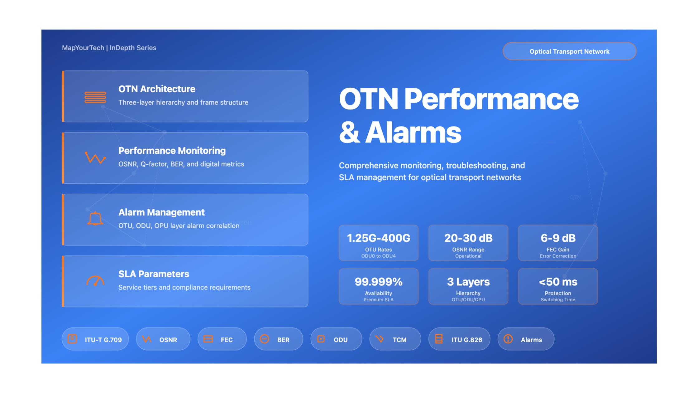
OTN Performance and Alarms

OTN Performance and Alarms

37 min read
123
OTN Performance and Alarms - Foundations & Architecture (Enhanced)

OTN Performance and Alarms

A comprehensive technical guide for optical network engineers
Introduction

Optical Transport Network (OTN) technology represents the backbone of modern telecommunications infrastructure, enabling high-capacity data transmission across metropolitan, regional, and long-haul networks. This enhanced guide provides network engineers with comprehensive technical knowledge of OTN performance monitoring and alarm management, incorporating detailed specifications from ITU-T G.709 standards and real-world operational data.

Understanding OTN performance parameters and alarm conditions is essential for maintaining network reliability, optimizing capacity utilization, and ensuring service level agreements are met. This first part establishes the foundational architecture and technical specifications that underpin all OTN operations.

OTN Architecture Overview

Three-Layer Hierarchy

OTN employs a sophisticated three-layer multiplexing structure that provides flexibility, efficiency, and robust performance monitoring capabilities. Each layer serves distinct functions while maintaining hierarchical relationships:

Optical Channel Transport Unit (OTU) Layer

The OTU layer represents the complete end-to-end optical transport structure. It encapsulates the ODU payload with additional overhead for section monitoring and Forward Error Correction (FEC). The FEC overhead enables extended transmission distances by detecting and correcting bit errors introduced during optical transmission.

OTU Frame Structure:
• Frame size: 4 rows × 4080 columns
• ODU payload: 4 rows × 3824 columns
• FEC overhead: 4 rows × 256 columns
• Frame period: varies by OTU type (see Table 1)

Optical Channel Data Unit (ODU) Layer

The ODU layer provides path-level monitoring, tandem connection monitoring, and multiplexing capabilities. This layer supports up to six levels of Tandem Connection Monitoring (TCM), enabling network operators to monitor signal quality across different administrative domains.

ODU Frame Structure:
• Frame size: 4 rows × 3824 columns
• ODU overhead: 4 rows × 14 columns
• OPU area: 4 rows × 3810 columns
• Supports hierarchical multiplexing (ODU0 → ODU1 → ODU2 → ODU3 → ODU4)

Optical Channel Payload Unit (OPU) Layer

The OPU layer carries the actual client signals and provides payload-specific adaptation functions. It supports various mapping procedures including Generic Mapping Procedure (GMP), Asynchronous Mapping Procedure (AMP), and Bit-synchronous Mapping Procedure (BMP).

OTN Layer Hierarchy
OTN Three-Layer Architecture OTU Layer (Optical Channel Transport Unit) Section Monitoring • Forward Error Correction (FEC) • Physical Transport Frame: 4 rows × 4080 columns | Adds: FEC overhead (256 columns) ODU Layer (Optical Channel Data Unit) Path Monitoring • Tandem Connection Monitoring (TCM) • Multiplexing Frame: 4 rows × 3824 columns | Supports: 6 TCM levels, Hierarchical multiplexing OPU Layer (Optical Channel Payload Unit) Client Signal Adaptation • Payload Mapping • Justification Control Payload: 3810 columns | Mapping: GMP, AMP, BMP Client Signals Ethernet • SDH/SONET • Fibre Channel • Other CBR signals
Critical Technical Detail: The BIP-8 error detection code is computed over OPU columns 15 to 3824 of frame i, and inserted in the BIP-8 overhead location in frame i+2. This two-frame delay is essential for proper error detection and must be accounted for in performance monitoring systems.
OTN Bit Rates and Specifications

Standard OTN Bit Rates

ITU-T G.709 defines precise bit rates for all OTN signal hierarchies. These rates are mathematically derived from SDH/SONET base rates with specific multipliers to accommodate overhead bytes and maintain synchronization.

Signal Type OPUk Rate (kbit/s) ODUk Rate (kbit/s) OTUk Rate (kbit/s) Tolerance Frame Period
ODU0/OPU0 1,238,954.310 1,244,160.000 ±20 ppm 98.354 μs
OTU1/ODU1/OPU1 2,488,320.000 2,498,775.126 2,666,057.143 ±20 ppm 48.971 μs
OTU2/ODU2/OPU2 9,995,276.962 10,037,273.924 10,709,225.316 ±20 ppm 12.191 μs
ODU2e/OPU2e 10,356,012.658 10,399,525.316 ±100 ppm 11.767 μs
OTU3/ODU3/OPU3 40,150,519.322 40,319,218.983 43,018,413.559 ±20 ppm 3.035 μs
OTU4/ODU4/OPU4 104,355,975.330 104,794,445.815 111,809,973.568 ±20 ppm 1.168 μs
OTU25/ODU25/OPU25 26,299,210.130 26,409,711.013 26,409,711.013 ±20 ppm 4.633 μs
OTU50/ODU50/OPU50 52,598,420.261 52,819,422.026 52,819,422.026 ±20 ppm 2.317 μs
OTUCn/ODUCn/OPUCn n × 104,817,727.434 n × 105,258,138.053 n × 105,258,138.053 ±20 ppm 1.163 μs
Notes on Bit Rate Calculations:
• OTU1 = 255/238 × 2,488,320 kbit/s ≈ 2,666,057.143 kbit/s
• OTU2 = 255/237 × 9,953,280 kbit/s ≈ 10,709,225.316 kbit/s
• OTU3 = 255/236 × 39,813,120 kbit/s ≈ 43,018,413.559 kbit/s
• OTU4 = 255/227 × 99,532,800 kbit/s ≈ 111,809,973.568 kbit/s
• The factor 255/238 (or similar) accounts for overhead and FEC

Bit Rate Derivation Example: ODU1

Understanding how OTN bit rates are calculated is essential for network design and troubleshooting. Let's examine the ODU1 rate derivation:

Step 1: Start with OPU1 Base Rate
OPU1 payload rate = 2,488,320 kbit/s (STM-16 rate)

Step 2: Add ODU1 Overhead
ODU1 overhead: 16 bytes per row × 4 rows = 64 bytes per frame
OPU1 payload: 3808 bytes per row × 4 rows = 15,232 bytes per frame
Total ODU1 frame: 15,232 + 64 = 15,296 bytes per frame

ODU1 rate = OPU1 rate × (3808 + 16) / 3808
ODU1 rate = 2,488,320 × (239/238) ≈ 2,498,775.126 kbit/s

Step 3: Add OTU1 Overhead and FEC
OTU1 adds FEC overhead: 256 bytes per frame
OTU1 rate = ODU1 rate × (3824 + 256) / 3824
OTU1 rate = 2,498,775.126 × (255/239) ≈ 2,666,057.143 kbit/s

Extended Rates for Ethernet and Fibre Channel

In addition to standard rates with ±20 ppm tolerance, OTN defines extended rates with ±100 ppm tolerance to support asynchronous client signals such as 10 Gigabit Ethernet and Fibre Channel.

Signal Type Client Signal OPUk Rate (kbit/s) ODUk Rate (kbit/s) Tolerance
ODU1e 10GbE LAN 10,312,500.000 10,355,829.832 ±100 ppm
ODU1f 10G FC 10,518,750.000 10,562,946.429 ±100 ppm
ODU2e 10GbE LAN 10,356,012.658 10,399,525.316 ±100 ppm
ODU2f 10G FC 10,563,132.911 10,607,515.823 ±100 ppm
ODUflex(CBR) Variable CBR Client signal bit rate 239/238 × client rate ±100 ppm
Frame Structure and Overhead

Frame Alignment Signal (FAS)

Frame alignment is the first critical step in OTN signal processing. The receiver must locate the frame boundary before any overhead information can be extracted or payload data can be recovered.

FAS Pattern (Critical): The Frame Alignment Signal consists of a fixed 6-byte pattern:
0xF6 F6 F6 28 28 28 (hexadecimal)
This pattern appears in row 1, columns 1-6 of every OTU frame. Any deviation indicates Loss of Frame (LOF).

Frame Alignment Process

The frame alignment process operates in two states:

Out-of-Frame (OOF) State:
• Search for a 4-byte subset of the FAS pattern
• Confirm by finding the same pattern one frame period later
• Transition to In-Frame state upon confirmation

In-Frame (IF) State:
• Continuously verify FAS pattern at expected position
• Check OA1OA2OA2 pattern (bytes 3, 4, 5 of row 1)
• Declare OOF if pattern missing in 5 consecutive frames
• Maintain frame start position during OOF state

Multi-Frame Alignment Signal (MFAS)

The MFAS provides a 256-frame superstructure that enables various overhead signals to be distributed across multiple frames. This is essential for transmitting 64-byte Trail Trace Identifiers and other multi-frame overhead.

MFAS Location: Row 1, Column 7
Counter Range: 0x00 to 0xFF (256 values)
Purpose: Multi-frame synchronization for overhead distribution

Overhead Byte Allocation

Row Columns Function Description
1 1-6 FAS Frame Alignment Signal (0xF6F6F6282828)
1 7 MFAS Multi-Frame Alignment Signal (0x00 to 0xFF)
1 8-10 SM Section Monitoring (BIP-8, TTI, BEI, BDI)
1 11-12 GCC0 General Communication Channel 0
1 13-14 RES Reserved for future use
2 1 RES Reserved byte
2 2-3 PM/TCM ACT Path Monitoring and TCM Activation Control
2 4-12 TCM6-TCM4 Tandem Connection Monitoring levels 6-4
2 13 FTFL Fault Type and Fault Location
2 14 RES Reserved
3 1-9 TCM3-TCM1 Tandem Connection Monitoring levels 3-1
3 10-12 PM Path Monitoring (BIP-8, TTI, Status)
3 13-14 EXP Experimental/Vendor-specific
4 1-2 GCC1/GCC2 General Communication Channels
4 3-4 APS/PCC Automatic Protection Switching
4 15 PSI Payload Structure Identifier
4 16 NJO Negative Justification Opportunity
OTU Frame Structure
OTU Frame Structure (4 rows × 4080 columns) Columns: 1 15 17 3825 4080 Rows: 1 2 3 4 Framing OTU OH OPU OH Payload OTU FEC ODU OH OAM Overhead 1-14 15 16 17-3824 (Payload area) 3825-4080 Legend: Framing ODU OH OPU OH Payload FEC
Forward Error Correction (FEC)

FEC Overview and Benefits

Forward Error Correction is one of OTN's most valuable features, enabling extended transmission distances without electrical regeneration. FEC adds redundant information that allows the receiver to detect and correct bit errors introduced during optical transmission.

FEC Capabilities:
• Corrects up to 8 bit errors per codeword
• Detects up to 16 bit errors per codeword
• Provides approximately 6 dB coding gain
• Extends transmission reach by 50-100%

FEC Performance Thresholds

Performance Level Pre-FEC BER Post-FEC BER Corrected Errors/sec Status
Excellent < 1×10⁻⁶ < 1×10⁻¹⁵ < 100 Normal operation
Good 1×10⁻⁶ to 1×10⁻⁴ < 1×10⁻¹² 100 - 10,000 Monitor closely
Degraded (FEC-DEG) 1×10⁻⁴ to 1×10⁻³ 1×10⁻¹² to 1×10⁻⁹ 10,000 - 100,000 Minor alarm
Excessive (FEC-EXC) > 1×10⁻³ > 1×10⁻⁹ > 100,000 Major alarm
FEC Failure > 1×10⁻² Uncorrectable N/A Critical alarm
Operational Guidance: When FEC-DEG alarms occur, schedule maintenance during the next available window. When FEC-EXC alarms occur, immediate investigation is required as service degradation is imminent. These thresholds should be configured in your network management system to enable proactive maintenance.
Multiplexing Hierarchy

Hierarchical Multiplexing Structure

OTN supports sophisticated multiplexing schemes that enable efficient bandwidth utilization. Lower-rate ODUs can be multiplexed into higher-rate ODUs using either Asynchronous Mapping Procedure (AMP) or Generic Mapping Procedure (GMP).

Server ODU Client Signals Supported Multiplexing Capacity Method
ODU1 ODU0 2 × ODU0 AMP
ODU2 ODU0, ODU1, ODUflex 8×ODU0 or 4×ODU1 or 8×ODUflex AMP/GMP
ODU3 ODU0, ODU1, ODU2, ODU2e, ODUflex 32×ODU0 or 16×ODU1 or 4×ODU2 or 32×ODUflex AMP/GMP
ODU4 ODU0, ODU1, ODU2, ODU2e, ODU3, ODUflex 80×ODU0 or 40×ODU1 or 10×ODU2 or 2×ODU3 or 80×ODUflex GMP
ODUCn ODU0, ODU1, ODU2, ODU2e, ODU3, ODU4, ODUflex 10n×ODU0 or 10n×ODU1 or 10n×ODU2 or n×ODU4 GMP
ODU Multiplexing Hierarchy
Hierarchical ODU Multiplexing Structure ODU0 1.25 Gbps ODU1 2.5 Gbps ODU2 10 Gbps 8×ODU0 4×ODU1 ODU3 40 Gbps 4×ODU2 32×ODU0 / 16×ODU1 ODU4 100 Gbps 2×ODU3 10×ODU2 40×ODU1 / 80×ODU0 Multiplexing Capacity Examples: • ODU2 can carry: 8×ODU0 OR 4×ODU1 OR mix of both

Tributary Slot Allocation

OTN uses the concept of tributary slots to allocate bandwidth within higher-rate ODUs. Different ODU types use different tributary slot granularities:

Tributary Slot Sizes:
• ODU2: 1.25 Gbps tributary slots (2.5 Gbps slots also available)
• ODU3: 1.25 Gbps tributary slots (2.5 Gbps slots also available)
• ODU4: 1.25 Gbps tributary slots
• ODUCn: 5 Gbps tributary slots

Example: To transport an ODU2 (10G) signal in ODU4:
• ODU2 requires 8 × 1.25G tributary slots
• Mapped using GMP into ODTU4.8 structure
• Inserted at specific tributary slot positions in OPU4
Client Signal Mapping

Supported Client Signals

OTN provides standardized mapping procedures for numerous client signal types, ensuring interoperability and efficient transport across multi-vendor networks.

Client Signal Bit Rate OTN Container Mapping Method
STM-1 / OC-3 155.52 Mbit/s ODU0 BMP
STM-4 / OC-12 622.08 Mbit/s ODU0 BMP
STM-16 / OC-48 2,488.32 Mbit/s ODU1 BMP
STM-64 / OC-192 9,953.28 Mbit/s ODU2 BMP
10GbE LAN 10,312.5 Mbit/s ODU2e BMP
10GbE WAN 9,953.28 Mbit/s ODU2 BMP
40GbE 41,250 Mbit/s ODU3 GMP
100GbE 103,125 Mbit/s ODU4 GMP
Fibre Channel 8G 8,500 Mbit/s ODU2 GMP
Fibre Channel 16G 14,025 Mbit/s ODU3 GMP
Premium Article — Free 20% Preview

Read the Full Analysis with Premium

The remaining 80% of this article — the design numbers, trade-offs and field guidance — is part of MapYourTech Premium, along with the full premium library, courses and professional tools.

Instant access · Cancel anytime · 48-hour trial available
Sanjay Yadav

Optical Communications & Network Automation Expert | Author of 3 Books for Optical Engineers | Founder, MapYourTech

Optical networking engineer with nearly two decades of experience across DWDM, OTN, coherent optics, submarine systems, and cloud infrastructure. Founder of MapYourTech.

Follow on LinkedIn
Share:

You May Also Like

15 min read 14 0 Like Connector Types and Their Loss Budgets: SC, LC, MPO Skip to main content MapYourTech...
  • Free
  • July 11, 2026
16 min read 12 0 Like Cooled vs Uncooled Lasers: The Pluggable Power Trade-off Skip to main content MapYourTech |...
  • Free
  • July 11, 2026
16 min read 18 0 Like Automation Blast Radius: Scoping What a Bad Intent Can Touch Skip to main content...
  • Free
  • July 11, 2026

Course Title

Course description and key highlights

Course Content

Course Details


