
What is PCS ?
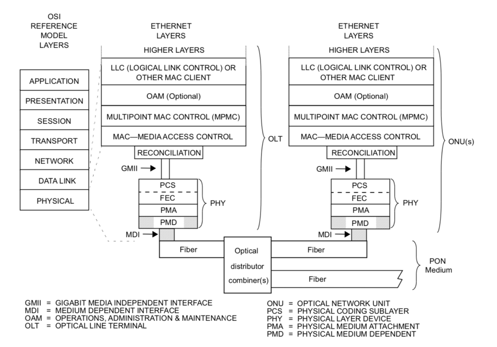
The Physical Coding Sublayer (PCS) is a networking protocol sublayer in the Ethernet standards. This layer resides at the top of the physical layer (PHY) which provides an interface between the Physical Medium Attachment (PMA) sublayer and the media-independent interface (MII). This layer is responsible for coding and decoding data streams flowing to and from the MAC layer , scrambling and descrambling it, block and symbol redistribution, alignment marker insertion and removal, and lane block synchronisation .Currently most of the optical client ports supports PCS lane to enable high data rate .
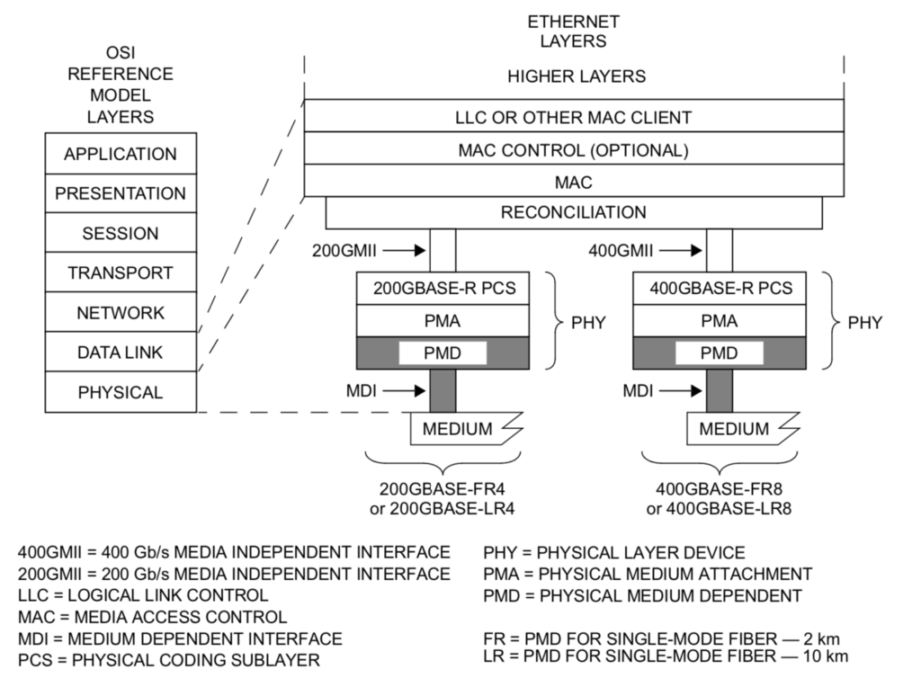
Where actually PCS layer lies ?
e.g
How to troubleshoot PCS errors issues in Optical Network links?
If you see PCS errors on the interfaces; it may cause the link to flap or you can see errors on the client interfaces of the optical or router ports. PCS block reports signal fail/signal degrade too based on pre-set thresholds.
- Sometime you may see bit errors or error block in the performance of the interface.Bit errors can also be converted to PCS errors.PCS errors are generally due to physical component degrade or failure issues like problem in physical interface mapper, damaged or attenuated fiber, issue on patch panel,ODF or due to faulty or damaged optic pluggables. The higher rate we go the complexity of the internal mapper/components increases so performance becomes more sensitive to optical path perturberation .
- PCS errors are also visible on the interfaces if there is some activity involving manual fiber pull ,device reboots ,optics replacement etc. During link bring-up or bring down or flapping kind of situation, it is expected to see PCS errors increase for a short interval of time; which is because of the initial synchronization or skew-deskew process of the two Ethernet end points. PCS errors are always counted from the incoming direction on the receiving node.
- The other reasons to see PCS errors could be damaged or bad fiber, faulty optical pluggable (sfp/xfp/cfp etc).
- Low receive power on the interface can also result in this kind of error so it is always recommended to troubleshoot or investigate on physical fiber as well as physical port on the devices(router/optical client ports).
For PCS lane based modules like SR4,LR4 ,LR10 or multi lane pluggables ,it is recommended to see errors on the lanes of the pluggable. if only few lanes are having issue ,it is better to suspect the connector or the optical XFP/CFP.
Also there is a limit for max difference in receive/transmit power between any two lanes .If the difference is greater than the threshold it may also result in issues.
Max Difference in receive power between any two lanes
100GBASE-LR4 5.5dB
200GBASE-FR4 4.1dB
200GBASE-LR4 4.2dB
400GBASE-FR8 4.1dB
400GBASE-LR8 4.5dB
Max Difference in transmit power between any two lanes
100GBASE-LR4 5dB
200GBASE-FR4 3.6dB
200GBASE-LR4 4 dB
400GBASE-FR8 4dB
400GBASE-LR8 4.5dB
e.g
Consider the case of using an LR4 CFP for the optical transceiver; each of the 4 wavelengths used on the link will be carrying 5 PCS lanes. In the case of 5 of the PCS lanes being in errors this may indicate the errors being specific to that wavelength and so areas of investigation should include the individual transmitters and receivers within the CFP.
If a 10 lane CFP (SR10 or LR10) is being used then each wavelength (in the case of the LR10) or fibre (in the case of the SR10) would each be carrying two PCS lanes. In this case then if two PCS lanes within the same CAUI lane are found to contain errors or defects then as well as investigating the CAUI the two lanes would also be carried on the same wavelength or fibre. In this case once again the optical components should be investigated at both ends of the link. In the case of an SR10 based link the multi-fibre cable should also be checked as it may be possible that one of the individual fibres has been damaged within the cable.
CAUI -(Chip to) 100Gb/s Attachment Unit Interface
CFP :Centum Form factor Pluggable
Reference:https://testing100g.net/troubleshooting-100g-links-with-pcs-lanes/


