Animated CTA Banner
MapYourTech
MapYourTech has always been about YOUR tech journey, YOUR questions, YOUR thoughts, and most importantly, YOUR growth. It’s a space where we "Map YOUR Tech" experiences and empower YOUR ambitions.
To further enhance YOUR experience, we are working on delivering a professional, fully customized platform tailored to YOUR needs and expectations.
Thank you for the love and support over the years. It has always motivated us to write more, share practical industry insights, and bring content that empowers and inspires YOU to excel in YOUR career.
We truly believe in our tagline:
“Share, explore, and inspire with the tech inside YOU!”
Let us know what YOU would like to see next! Share YOUR thoughts and help us deliver content that matters most to YOU.
Share YOUR Feedback
Tag

Dispersion

Browsing

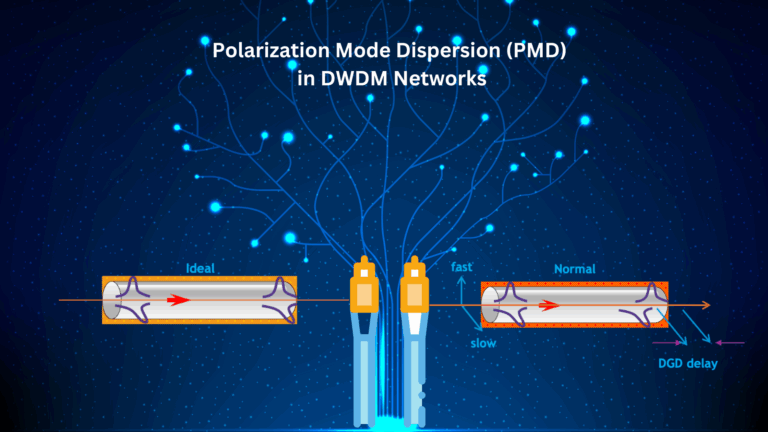
Polarization Mode Dispersion (PMD) is one of the significant impairments in optical fiber communication systems, particularly in Dense Wavelength Division Multiplexing (DWDM) systems where multiple wavelengths (channels) are transmitted simultaneously over a single optical fiber. PMD occurs because of the difference in propagation velocities between two orthogonal polarization modes in the fiber. This difference results in a broadening of the optical pulses over time, leading to intersymbol interference (ISI), degradation of signal quality, and increased bit error rates (BER).

PMD is caused by imperfections in the optical fiber, such as slight variations in its shape, stress, and environmental factors like temperature changes. These factors cause the fiber to become birefringent, meaning that the refractive index experienced by light depends on its polarization state. As a result, light polarized in one direction travels at a different speed than light polarized in the perpendicular direction.

The Physics of PMD

PMD arises from the birefringence of optical fibers. Birefringence is the difference in refractive index between two orthogonal polarization modes in the fiber, which results in different group velocities for these modes. The difference in arrival times between the two polarization components is called the Differential Group Delay (DGD).

The DGD is given by:

Where:

  • L is the length of the fiber.
  • Δn is the difference in refractive index between the two polarization modes.
  • c is the speed of light in vacuum.

This DGD causes pulse broadening, as different polarization components of the signal arrive at the receiver at different times. Over long distances, this effect can accumulate and become a major impairment in optical communication systems.

Polarization Mode Dispersion and Pulse Broadening

The primary effect of PMD is pulse broadening, which occurs when the polarization components of the optical signal are delayed relative to one another. This leads to intersymbol interference (ISI), as the broadened pulses overlap with adjacent pulses, making it difficult for the receiver to distinguish between symbols. The amount of pulse broadening increases with the DGD and the length of the fiber.

The PMD coefficient is typically measured in ps/√km, which represents the DGD per unit length of fiber. For example, in standard single-mode fibers (SSMF), the PMD coefficient is typically around 0.05–0.5 ps/√km. Over long distances, the total DGD can become significant, leading to substantial pulse broadening.

Statistical Nature of PMD

PMD is inherently stochastic, meaning that it changes over time due to environmental factors such as temperature fluctuations, mechanical stress, and fiber bending. These changes cause the birefringence of the fiber to vary randomly, making PMD difficult to predict and compensate for. The random nature of PMD is usually described using statistical models, such as the Maxwellian distribution for DGD.

The mean DGD increases with the square root of the fiber length, as given by:

Where:

  • τPMD is the PMD coefficient of the fiber.
  • L is the length of the fiber.

PMD in Coherent Systems

In modern coherent optical communication systems, PMD can have a severe impact on system performance. Coherent systems rely on both the phase and amplitude of the received signal to recover the transmitted data, and any phase distortions caused by PMD can lead to significant degradation in signal quality. PMD-induced phase shifts lead to phase noise, which in turn increases the bit error rate (BER).

Systems using advanced modulation formats, such as Quadrature Amplitude Modulation (QAM), are particularly sensitive to PMD, as these formats rely on accurate phase information to recover the transmitted data. The nonlinear phase noise introduced by PMD can interfere with the receiver’s ability to correctly demodulate the signal, leading to increased errors.

Formula for PMD-Induced Pulse Broadening

The pulse broadening due to PMD can be expressed as:

Where:

  • τDGD​ is the differential group delay.
  • L is the fiber length.

This equation shows that the amount of pulse broadening increases with both the DGD and the fiber length. Over long distances, the cumulative effect of PMD can cause significant ISI and degrade system performance.

Detecting PMD in DWDM Systems

Engineers can detect PMD in DWDM networks by monitoring several key performance indicators (KPIs):

  1. Increased Bit Error Rate (BER): PMD-induced phase noise and pulse broadening lead to higher BER, particularly in systems using high-speed modulation formats like QAM.
            • KPI: Real-time BER monitoring. A significant increase in BER, especially over long distances, is a sign of PMD.
  2. Signal-to-Noise Ratio (SNR) Degradation: PMD introduces phase noise and pulse broadening, which degrade the SNR. Operators may observe a drop in SNR in the affected channels.
            • KPI: SNR monitoring tools that provide real-time feedback on the quality of the transmitted signal.
  3. Pulse Shape Distortion: PMD causes temporal pulse broadening and distortion. Using an optical sampling oscilloscope, operators can visually inspect the shape of the transmitted pulses to identify any broadening caused by PMD.
  4. Optical Spectrum Analyzer (OSA): PMD can lead to spectral broadening of the signal, which can be detected using an OSA. The analyzer will show the broadening of the spectrum of the affected channels, indicating the presence of PMD.

Mitigating PMD in DWDM Systems

Several strategies can be employed to mitigate the effects of PMD in DWDM systems:

  1. PMD Compensation Modules: These are adaptive optical devices that compensate for the differential group delay introduced by PMD. They can be inserted periodically along the fiber link to reduce the total accumulated PMD.
  2. Digital Signal Processing (DSP): In modern coherent systems, DSP techniques can be used to compensate for the effects of PMD at the receiver. These methods involve applying adaptive equalization filters to reverse the effects of PMD.
  3. Fiber Design: Fibers with lower PMD coefficients can be used to reduce the impact of PMD. Modern optical fibers are designed to minimize birefringence and reduce the amount of PMD.
  4. Polarization Multiplexing: In polarization multiplexing systems, PMD can be mitigated by separating the signals transmitted on orthogonal polarization states and applying adaptive equalization to each polarization component.
  5. Advanced Modulation Formats: Modulation formats that are less sensitive to phase noise, such as Differential Phase-Shift Keying (DPSK), can help reduce the impact of PMD on system performance.

Polarization Mode Dispersion (PMD) is a critical impairment in DWDM networks, causing pulse broadening, phase noise, and intersymbol interference. It is inherently stochastic, meaning that it changes over time due to environmental factors, making it difficult to predict and compensate for. However, with the advent of digital coherent optical systems and DSP techniques, PMD can be effectively managed and compensated for, allowing modern systems to achieve high data rates and long transmission distances without significant performance degradation.

Summary

  • Different polarization states of light travel at slightly different speeds in a fiber, causing pulse distortion.
  • This variation can cause pulses to overlap or alter their shape enough to become undetectable at the receiver.
  • PMD occurs when the main polarization mode travels faster than the secondary mode, causing a delay known as Differential Group Delay (DGD).
  • PMD becomes problematic at higher transmission rates like 10, 40 or 100 Gbps etc.
  • Unlike chromatic dispersion, PMD is a statistical, non-linear phenomenon, making it more complex to manage.
  • PMD is caused by fiber asymmetry due to geometric imperfections, stress from the wrapping material, manufacturing processes, or mechanical stress during cable laying.
  • PMD is the average value of DGD distributions, which vary over time, and thus cannot be directly measured in the field.

Reference

  • https://www.wiley.com/en-ie/Fiber-Optic+Communication+Systems%2C+5th+Edition-p-9781119737360  

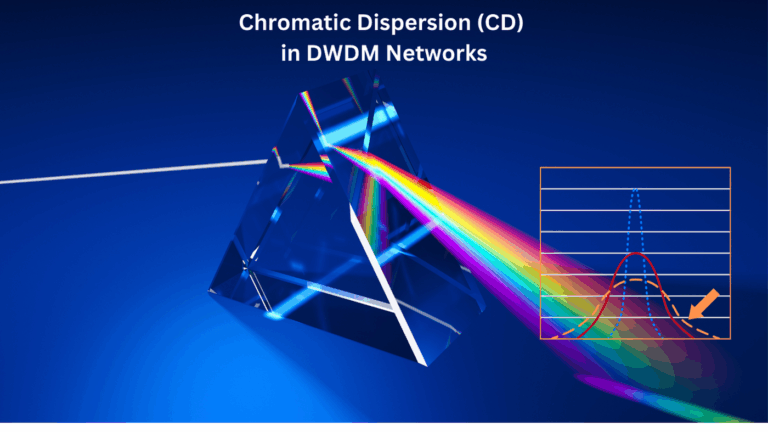
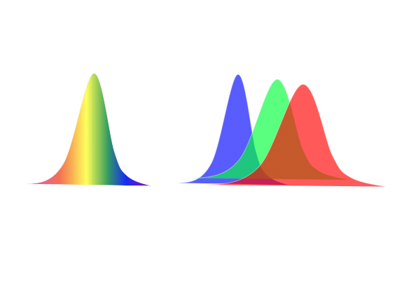
Chromatic Dispersion (CD) is a key impairment in optical fiber communication, especially in Dense Wavelength Division Multiplexing (DWDM) systems. It occurs due to the variation of the refractive index of the optical fiber with the wavelength of the transmitted light. Since different wavelengths travel at different speeds through the fiber, pulses of light that contain multiple wavelengths spread out over time, leading to pulse broadening. This broadening can cause intersymbol interference (ISI), degrading the signal quality and ultimately increasing the bit error rate (BER) in the network.With below details,I believe reader will be able to understand all about CD in the DWDM system.I have added some figures which can help visualise the affect of CD.

Physics behind Chromatic Dispersion

CD results from the fact that optical fibers have both material dispersion and waveguide dispersion. The material dispersion arises from the inherent properties of the silica material, while waveguide dispersion results from the interaction between the core and cladding of the fiber. These two effects combine to create a wavelength-dependent group velocity, causing different spectral components of an optical signal to travel at different speeds.

The relationship between the group velocity Vg​ and the propagation constant β is given by:

where:

  • ω is the angular frequency.
  • β is the propagation constant.

The propagation constant β typically varies nonlinearly with frequency in optical fibers. This nonlinear dependence is what causes different frequency components to propagate with different group velocities, leading to CD.

Chromatic Dispersion Effects in DWDM Systems

In DWDM systems, where multiple closely spaced wavelengths are transmitted simultaneously, chromatic dispersion can cause significant pulse broadening. Over long fiber spans, this effect can spread the pulses enough to cause overlap between adjacent symbols, leading to ISI. The severity of CD increases with:

  • Fiber length: The longer the fiber, the more time the different wavelength components have to disperse.
  • Signal bandwidth: A broader signal (wider range of wavelengths) is more susceptible to dispersion.

The amount of pulse broadening due to CD can be quantified by the Group Velocity Dispersion (GVD) parameter D, typically measured in ps/nm/km. The GVD represents the time delay per unit wavelength shift, per unit length of the fiber. The relation between the GVD parameter D and the second-order propagation constant β2 is:

Where:

  • c is the speed of light in vacuum.
  • λ is the operating wavelength.

Pulse Broadening Due to CD

The pulse broadening (or time spread) due to CD is given by:

Where:

  • D is the GVD parameter.
  • L is the length of the fiber.
  • Δλ is the spectral bandwidth of the signal.

For example, in a standard single-mode fiber (SSMF) with D=17 ps/nm/km at a wavelength of 1550 nm, a signal with a spectral width of 0.4 nm transmitted over 1000 km will experience significant pulse broadening, potentially leading to ISI and performance degradation in the network.

CD in Coherent Systems

In modern coherent optical systems, CD can be compensated for using digital signal processing (DSP) techniques. At the receiver, the distorted signal is passed through adaptive equalizers that reverse the effects of CD. This approach allows for complete digital compensation of chromatic dispersion, making it unnecessary to use optical dispersion compensating modules (DCMs) that were commonly used in older systems.

Chromatic Dispersion Profiles in Fibers

CD varies with wavelength. For standard single-mode fibers (SSMFs), the CD is positive and increases with wavelength beyond 1300 nm. DSFs were developed to shift the zero-dispersion wavelength from 1300 nm to 1550 nm, where fiber attenuation is minimized, making them suitable for older single-channel systems. However, in modern DWDM systems, DSFs are less preferred due to their smaller core area, which enhances nonlinear effects at high power levels .

Link to see CD in action

Impact of CD on System Performance

  1. Intersymbol Interference (ISI): As CD broadens the pulses, they start to overlap, causing ISI. This effect increases the BER, particularly in systems with high symbol rates and wide bandwidths.
  2. Signal-to-Noise Ratio (SNR) Degradation: CD can reduce the effective SNR by spreading the signal over a wider temporal window, making it harder for the receiver to recover the original signal.
  3. Spectral Efficiency: CD limits the maximum data rate that can be transmitted over a given bandwidth, reducing the spectral efficiency of the system.
  4. Increased Bit Error Rate (BER): The ISI caused by CD can lead to higher BER, particularly over long distances or at high data rates. The degradation becomes more pronounced at higher bit rates because the pulses are narrower, and thus more susceptible to dispersion.


Detection of CD in DWDM Systems

Operators can detect the presence of CD in DWDM networks by monitoring several key indicators:

  1. Increased BER: The first sign of CD is usually an increase in the BER, particularly in systems operating at high data rates. This increase occurs due to the intersymbol interference caused by pulse broadening.
  2. Signal-to-Noise Ratio (SNR) Degradation: CD can reduce the SNR, which can be observed using real-time monitoring tools.
  3. Pulse Shape Distortion: CD causes temporal pulse broadening and distortion. Using an optical sampling oscilloscope, operators can visually inspect the shape of the transmitted pulses to identify any broadening caused by CD.
  4. Optical Spectrum Analyzer (OSA): An OSA can be used to detect the broadening of the signal’s spectrum, which is a direct consequence of chromatic dispersion.

Mitigating Chromatic Dispersion

There are several strategies for mitigating CD in DWDM networks:

  1. Dispersion Compensation Modules (DCMs): These are optical devices that introduce negative dispersion to counteract the positive dispersion introduced by the fiber. DCMs can be placed periodically along the link to reduce the total accumulated dispersion.
  2. Digital Signal Processing (DSP): In modern coherent systems, CD can be compensated for using DSP techniques at the receiver. These methods involve applying adaptive equalization filters to reverse the effects of dispersion.
  3. Dispersion-Shifted Fibers (DSFs): These fibers are designed to shift the zero-dispersion wavelength to minimize the effects of CD. However, they are less common in modern systems due to the increase in nonlinear effects.
  4. Advanced Modulation Formats: Modulation formats that are less sensitive to ISI, such as Differential Phase-Shift Keying (DPSK), can help reduce the impact of CD on system performance.

Chromatic Dispersion (CD) is a major impairment in optical communication systems, particularly in long-haul DWDM networks. It causes pulse broadening and intersymbol interference, which degrade signal quality and increase the bit error rate. However, with the availability of digital coherent optical systems and DSP techniques, CD can be effectively managed and compensated for, allowing modern systems to achieve high data rates and long transmission distances without significant performance degradation.

Reference

https://webdemo.inue.uni-stuttgart.de/

Dispersion compensation-An Introduction

Fiber dispersion is one of the most critical parameters that need to be considered for high speed transmission design. Dispersion typically varies with wavelength and accumulates along a fiber length. Therefore it is difficult to precisely compensate for all the propagating channels with fixed optical compensation modules at the same time. When preferred, dispersion at each channel can be fully compensated electronically in the DSP of the receiver.

Dispersion compensation basically means eliminating the compounded dispersion originating from length of the fiber. There might be a misconception that having a fiber with zero dispersion would avoid such a drama. However this is not true as verified from older experience with dispersion-shifted fiber (DSF). A DSF is designed with zero dispersion between 1525 nm and 1575 nm. This would work perfectly for a single channel transmission inside this window. However in DWDM transmission, it gives rise to undesired levels Four Wave Mixing which renders DWDM transmission practically impossible. Therefore, the goal is not to reduce the dispersion to zero but to avoid excessive temporal broadening of the pulses so that the residual dispersion is still within the tolerable limits of the system.

Several technologies exist for chromatic dispersion compensation, such as dispersion compensating fiber/ unit (DCF/U), dispersion managed cables, higher-order mode DCF, fiber Bragg gratings and optical phase conjugation. The widely used compensation is via the dispersion compensating fiber. In general, chromatic dispersion can be compensated in lump or according to dispersion map/management. In lump compensation, the accumulated dispersion is compensated in bulk using in-line dispersion compensation while with dispersion management the local dispersion evolution along the link is compensated utilizing the DCFs as shown in the figure.

Dispersion compensating fiber, as the name implies, is actually a fiber with large negative dispersion parameter that can be inserted into the link at regular intervals. The compensating fiber typically has a dispersion of -100 ps/nm/km in the 1550 nm region and thus only a short length of this fiber would be required to compensate the accumulated dispersion arising from hundreds of km of transmission fiber. However, insertion of DCF is not addition of new fiber or doesn’t increase transmission distance. The added length of fiber is placed as a bulk at one end of the link. This nevertheless adds attenuation and additional amplification may be needed to compensate and achieve the desired reach. A typical DCF attenuation is about 0.5 dB/km.

As mentioned before, in a DWDM system, it is quite difficult to balance dispersion characteristic over a range of wavelengths i.e. for all the co-propagating channels. When residual dispersion for center channel of the DWDM spectrum has been compensated to zero, other channels at extremes will have significant finite dispersion. The dispersion compensation is therefore optimized in such a way such that the finite dispersion in the neighboring channel is either less than the tolerable range or then compensated electronically.

original link:http://blog.cubeoptics.com/index.php/2014/06/dispersion-compensation