
Chromatic Dispersion (CD) is a key impairment in optical fiber communication, especially in Dense Wavelength Division Multiplexing (DWDM) systems. It occurs due to the variation of the refractive index of the optical fiber with the wavelength of the transmitted light. Since different wavelengths travel at different speeds through the fiber, pulses of light that contain multiple wavelengths spread out over time, leading to pulse broadening. This broadening can cause intersymbol interference (ISI), degrading the signal quality and ultimately increasing the bit error rate (BER) in the network.With below details,I believe reader will be able to understand all about CD in the DWDM system.I have added some figures which can help visualise the affect of CD.
Physics behind Chromatic Dispersion
CD results from the fact that optical fibers have both material dispersion and waveguide dispersion. The material dispersion arises from the inherent properties of the silica material, while waveguide dispersion results from the interaction between the core and cladding of the fiber. These two effects combine to create a wavelength-dependent group velocity, causing different spectral components of an optical signal to travel at different speeds.
The relationship between the group velocity Vg and the propagation constant β is given by:
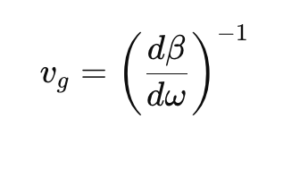 where:
- ω is the angular frequency.
- β is the propagation constant.
The propagation constant β typically varies nonlinearly with frequency in optical fibers. This nonlinear dependence is what causes different frequency components to propagate with different group velocities, leading to CD.
Chromatic Dispersion Effects in DWDM Systems
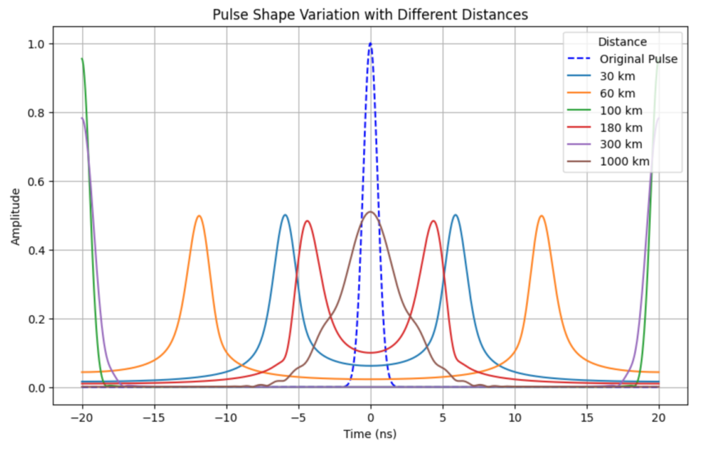
In DWDM systems, where multiple closely spaced wavelengths are transmitted simultaneously, chromatic dispersion can cause significant pulse broadening. Over long fiber spans, this effect can spread the pulses enough to cause overlap between adjacent symbols, leading to ISI. The severity of CD increases with:
- Fiber length: The longer the fiber, the more time the different wavelength components have to disperse.
- Signal bandwidth: A broader signal (wider range of wavelengths) is more susceptible to dispersion.
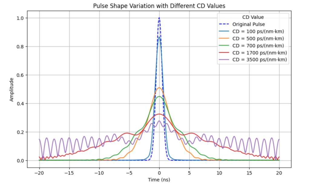
The amount of pulse broadening due to CD can be quantified by the Group Velocity Dispersion (GVD) parameter D, typically measured in ps/nm/km. The GVD represents the time delay per unit wavelength shift, per unit length of the fiber. The relation between the GVD parameter D and the second-order propagation constant β2 is:
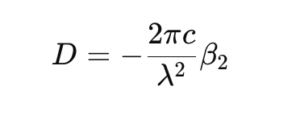
Where:
- c is the speed of light in vacuum.
- λ is the operating wavelength.
Pulse Broadening Due to CD
The pulse broadening (or time spread) due to CD is given by:
 Where:
- D is the GVD parameter.
- L is the length of the fiber.
- Δλ is the spectral bandwidth of the signal.
For example, in a standard single-mode fiber (SSMF) with D=17 ps/nm/km at a wavelength of 1550 nm, a signal with a spectral width of 0.4 nm transmitted over 1000 km will experience significant pulse broadening, potentially leading to ISI and performance degradation in the network.
CD in Coherent Systems
In modern coherent optical systems, CD can be compensated for using digital signal processing (DSP) techniques. At the receiver, the distorted signal is passed through adaptive equalizers that reverse the effects of CD. This approach allows for complete digital compensation of chromatic dispersion, making it unnecessary to use optical dispersion compensating modules (DCMs) that were commonly used in older systems.
Chromatic Dispersion Profiles in Fibers
CD varies with wavelength. For standard single-mode fibers (SSMFs), the CD is positive and increases with wavelength beyond 1300 nm. DSFs were developed to shift the zero-dispersion wavelength from 1300 nm to 1550 nm, where fiber attenuation is minimized, making them suitable for older single-channel systems. However, in modern DWDM systems, DSFs are less preferred due to their smaller core area, which enhances nonlinear effects at high power levels .
Link to see CD in action
Impact of CD on System Performance
- Intersymbol Interference (ISI): As CD broadens the pulses, they start to overlap, causing ISI. This effect increases the BER, particularly in systems with high symbol rates and wide bandwidths.
- Signal-to-Noise Ratio (SNR) Degradation: CD can reduce the effective SNR by spreading the signal over a wider temporal window, making it harder for the receiver to recover the original signal.
- Spectral Efficiency: CD limits the maximum data rate that can be transmitted over a given bandwidth, reducing the spectral efficiency of the system.
- Increased Bit Error Rate (BER): The ISI caused by CD can lead to higher BER, particularly over long distances or at high data rates. The degradation becomes more pronounced at higher bit rates because the pulses are narrower, and thus more susceptible to dispersion.
Detection of CD in DWDM Systems
Operators can detect the presence of CD in DWDM networks by monitoring several key indicators:
- Increased BER: The first sign of CD is usually an increase in the BER, particularly in systems operating at high data rates. This increase occurs due to the intersymbol interference caused by pulse broadening.
- Signal-to-Noise Ratio (SNR) Degradation: CD can reduce the SNR, which can be observed using real-time monitoring tools.
- Pulse Shape Distortion: CD causes temporal pulse broadening and distortion. Using an optical sampling oscilloscope, operators can visually inspect the shape of the transmitted pulses to identify any broadening caused by CD.
- Optical Spectrum Analyzer (OSA): An OSA can be used to detect the broadening of the signal’s spectrum, which is a direct consequence of chromatic dispersion.
Mitigating Chromatic Dispersion
There are several strategies for mitigating CD in DWDM networks:
- Dispersion Compensation Modules (DCMs): These are optical devices that introduce negative dispersion to counteract the positive dispersion introduced by the fiber. DCMs can be placed periodically along the link to reduce the total accumulated dispersion.
- Digital Signal Processing (DSP): In modern coherent systems, CD can be compensated for using DSP techniques at the receiver. These methods involve applying adaptive equalization filters to reverse the effects of dispersion.
- Dispersion-Shifted Fibers (DSFs): These fibers are designed to shift the zero-dispersion wavelength to minimize the effects of CD. However, they are less common in modern systems due to the increase in nonlinear effects.
- Advanced Modulation Formats: Modulation formats that are less sensitive to ISI, such as Differential Phase-Shift Keying (DPSK), can help reduce the impact of CD on system performance.
Chromatic Dispersion (CD) is a major impairment in optical communication systems, particularly in long-haul DWDM networks. It causes pulse broadening and intersymbol interference, which degrade signal quality and increase the bit error rate. However, with the availability of digital coherent optical systems and DSP techniques, CD can be effectively managed and compensated for, allowing modern systems to achieve high data rates and long transmission distances without significant performance degradation.
Reference
https://webdemo.inue.uni-stuttgart.de/


