Spectral Width in Optical Communication – Complete Guide Spectral Width in Optical Communication A Comprehensive Guide to Understanding Signal Bandwidth...
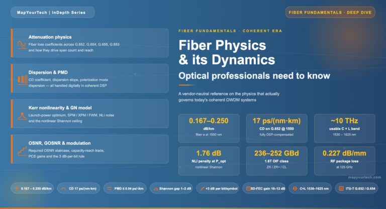
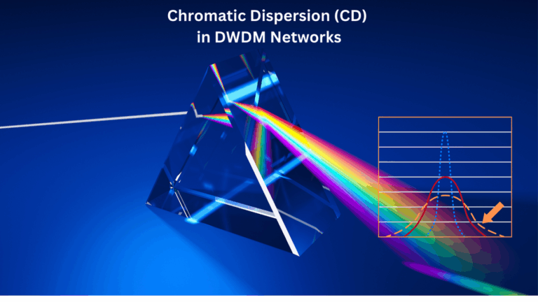
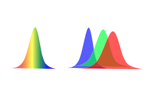
Chromatic Dispersion (CD) is a key impairment in optical fiber communication, especially in Dense Wavelength Division Multiplexing (DWDM) systems. It...
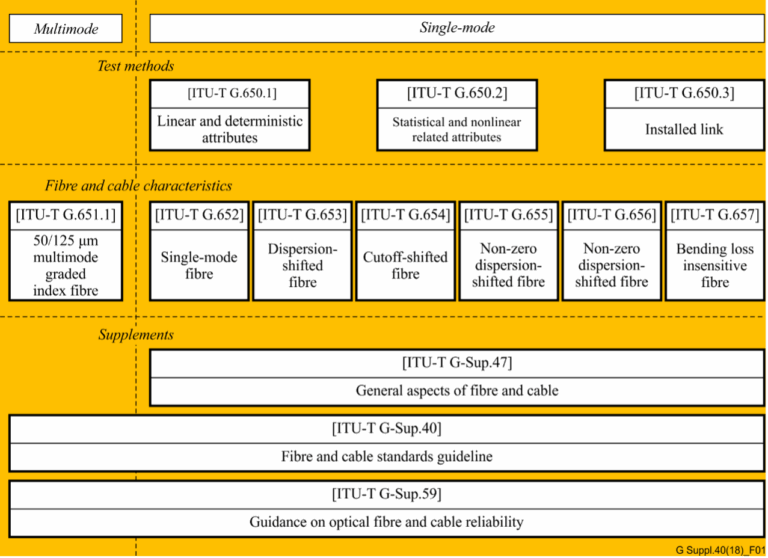
In the realm of telecommunications, the precision and reliability of optical fibers and cables are paramount. The International Telecommunication Union...
Chromatic dispersion affects all optical transmissions to some degree.These effects become more pronounced as the transmission rate increases and fiber length...