
What Is a Branching Unit in Submarine Cable Networks?
How branching units route fibers, reconfigure power, and — with ROADM and WSS technology — enable dynamic spectrum management between landing stations.
Introduction
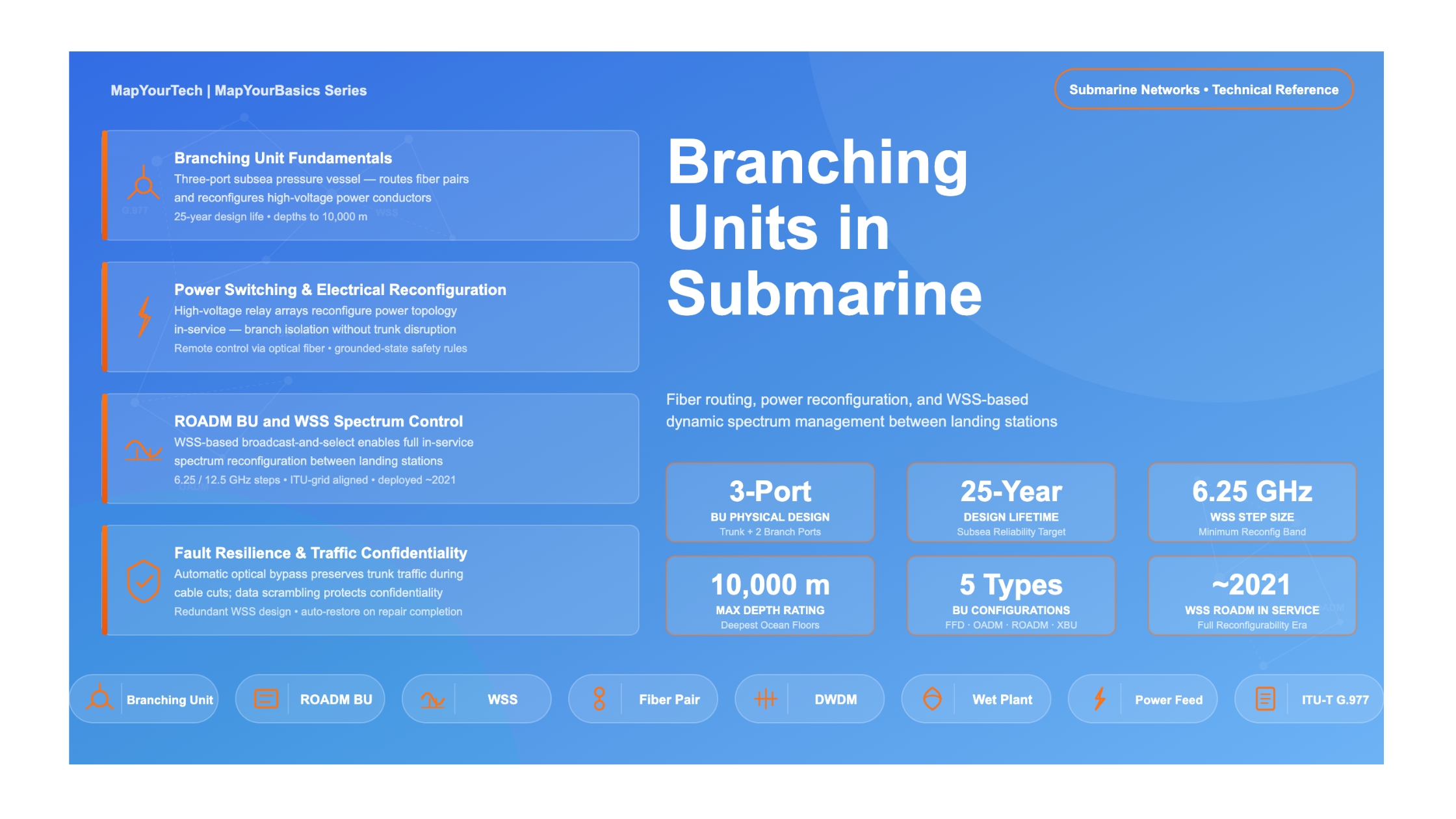
Submarine cable systems carry most of the world's international internet and voice traffic. While repeaters and terminals get a lot of attention, the branching unit (BU) is an equally important element — it is the subsea junction that allows a single cable system to serve three or more landing points instead of just two.
Without branching units, every additional destination country would need its own separate cable, dramatically increasing the cost of global connectivity. A BU sits on the seafloor at the intersection of a trunk cable and one or more branch cables, handling both the routing of optical fiber pairs and the reconfiguration of high-voltage power conductors. In modern systems, BUs work alongside Reconfigurable Optical Add/Drop Multiplexer (ROADM) units equipped with Wavelength Selective Switches (WSS) to give operators full, in-service control over how spectrum is divided between landing stations — without having to deploy a ship.
This article explains what a branching unit does, the different types in service today, how power switching works, and how ROADM-based BUs have evolved to support dynamic spectrum management.
What a Branching Unit Actually Does
A branching unit is a three-port pressure vessel designed to survive depths exceeding 10,000 m, with a 25-year design lifetime. Physically, it resembles a large repeater — with one cable end on one side and two cable ends on the other. Inside, it contains spliced optical fibers and high-voltage electrical switching components.
The BU addresses two completely separate functions: optical routing and electrical power reconfiguration. Transmission is always bidirectional, carried over fiber pairs (FPs). Each fiber pair provides one optical channel in each direction.
Key point: A branching unit connects three cables — a trunk (the main highway between major stations) and at least one branch (a spur to a smaller landing point). Traffic is carried bidirectionally over fiber pairs throughout the entire wet plant.
Types of Branching Units
Branching units are not all the same. They can be equipped with different optical and electrical features depending on network requirements. The choice of BU type has a direct impact on capacity, flexibility, and long-term operational cost.
Passive Full Fiber Drop (FFD) BU
The simplest type contains no optical switching. The entire spectrum of a fiber pair is routed completely to the branch — hence "full fiber drop." If you want to connect Station C to both Station A and Station B with 100 Gbps each, and the trunk carries 200 Gbps, an FFD BU would consume two separate fiber pairs: one to carry A-to-C traffic and one to carry B-to-C traffic. This is straightforward but not spectrum-efficient on high-capacity trunks.
OADM BU (Optical Add/Drop Multiplexer)
An Optical Add/Drop Multiplexer (OADM) BU uses passive optical filters or couplers to divide the spectrum of a single fiber pair between trunk pass-through channels and channels destined for the branch. This allows one fiber pair to serve both trunk and branch traffic simultaneously, reducing the number of fiber pairs needed — and therefore reducing cable cost. The trade-off is that filter positions are fixed at installation time, meaning bandwidth allocation cannot be changed without a ship repair.
ROADM BU (Reconfigurable OADM)
The ROADM BU introduced full in-service reconfigurability. Early ROADM BUs, first deployed in submarine systems around 2015 (for example in SMW5), used a combination of optical switches and multiple fixed passband filters, providing a set of preplanned filter scenarios that could be selected remotely. While an improvement over purely passive OADM, the number of available configurations was limited by the fixed filter inventory.
The step change came with the introduction of Wavelength Selective Switch (WSS) technology inside ROADM units, which became widely specified around 2018 and entered service approximately 2021. WSS-based ROADMs provide fully arbitrary, on-demand spectrum splitting — any portion of the spectrum can be directed to the branch or kept on the trunk, reconfigured from shore through the Submarine Network Manager at any time.
Fiber Switching BU (XBU)
As submarine cable systems have moved toward higher fiber pair counts — 16 FP and 24 FP systems and beyond — a new category has emerged: the fiber switching unit (also called XBU). Rather than managing spectrum within a single fiber pair, the XBU can switch entire fiber pairs between trunk and branch paths. This provides coarse routing at fiber-pair granularity, for example directing 25% of total system capacity to a branch by switching a set of four FPs in a 16 FP system. On systems with enough fiber pairs, this approach can avoid the need for ROADMs on some nodes while still allowing meaningful capacity reconfiguration.
Passive FFD BU
No optical switching. Entire fiber pair drops to branch. Simple, reliable, but requires more fiber pairs. Best for low-connectivity scenarios.
OADM BU
Passive filters split spectrum between trunk and branch on a single fiber pair. Reduces FP count but spectrum allocation is fixed at installation.
ROADM BU (WSS)
Fully reconfigurable in-service. WSS devices enable arbitrary spectrum allocation between trunk and branch, remotely adjustable throughout system life.
Fiber Switching BU (XBU)
Routes whole fiber pairs to trunk or branch. Suited for high-FP-count systems where FP-granularity routing is sufficient without per-wavelength control.
Power Switching and Electrical Reconfiguration
Submarine cables rely on high-voltage, constant-current power feeding from shore stations. The BU must not only route optical fiber pairs but also connect and reconfigure the high-voltage electrical conductors of the trunk and branch cables. This is one of the most operationally critical functions of the BU — getting it wrong can leave parts of the wet plant unpowered or, worse, create hazards for cable ship personnel during repairs.
Early BU designs had fixed electrical routing, which meant the entire system had to be depowered to perform maintenance on any segment. Modern BUs contain an array of high-voltage latching or non-latching relays that can reconfigure the power topology in-service, controlled by sequential voltage and current commands sent from shore-based Power Feed Equipment (PFE). Remote commands can also be sent over the optical fiber path itself.
Safety rule: All power configuration transitions must begin and end with the grounded state, ensuring cables are fully discharged before new conductor connections are made inside the BU. This protects both the equipment and the ship personnel involved in any repair operations.
A key operational scenario is branch isolation: if the branch cable between the BU and Station C is damaged, the BU power switching can isolate the branch electrically while keeping the trunk segment between Stations A and B fully operational and powered. This allows cable repairs to proceed on the affected branch without disrupting trunk traffic.
ROADM BU Architecture and WSS Operation
A ROADM BU is physically composed of two separate pressure housings deployed close together on the seafloor: the FFD BU, which handles the physical fiber pair routing and power switching, and the ROADM unit, which provides the wavelength management and spectrum splitting functions.
WSS Filtering Inside the ROADM Unit
The ROADM unit uses passive couplers (CPLRs) to broadcast the full inbound optical spectrum from both the trunk and branch-add ports to the inputs of WSS configurable filters. Two WSS devices — typically a Drop-WSS and an Add-WSS — then select specific portions of the spectrum to route toward the trunk output or the branch drop output. This broadcast-and-select architecture allows the portions of trunk spectrum that are dropped at the branch station to be reused by branch-add traffic, which is essential for spectral efficiency.
WSS devices in subsea-hardened ROADM units typically provide reconfigurable bandwidth steps of 6.25 or 12.5 GHz, aligned to the ITU grid. Because WSS filters have much sharper passband roll-off than older thin-film filters, the guard band between trunk and branch spectrum bands is reduced to approximately 10–20 GHz — essentially eliminating the dead zones that cost capacity in earlier fixed-filter OADM designs.
WSS vs. Fixed Filter Performance
Older thin-film filter (TFF)-based OADM designs require guard bands between channel groups, consuming spectrum that could carry traffic. WSS-based ROADMs reduce this overhead to approximately 10–20 GHz at each band boundary, and their sharp filter transitions allow many more passbands on a single fiber pair without spectrum penalty. This directly increases the usable capacity at each branching node.
Fault Resilience and Optical Bypass
A ROADM BU includes an automatic optical bypass function. If the branch cable between the BU and Station C is damaged (fiber cut or shunt fault), the ROADM unit detects the loss and routes the full trunk wavelength comb straight through, bypassing all branch add/drop functions. Trunk traffic between Stations A and B continues uninterrupted. When the branch repair is complete, the ROADM automatically restores normal add/drop operation.
Conversely, if a trunk cable segment is cut, the Submarine Network Manager can activate an optical switch within the BU or ROADM to re-route traffic through the available branch path, preserving connectivity to the maximum number of stations during the repair window.
Traffic Confidentiality
Because the broadcast-and-select architecture physically sends the full trunk spectrum to the branch coupler, any branch station could in principle receive trunk wavelengths not intended for it. The ROADM unit addresses this through data scrambling: trunk wavelengths broadcast to the branch are scrambled at the SLTE (Submarine Line Terminal Equipment), and only the intended dropped wavelengths can be decoded by the branch station. If a branch cable fault causes trunk traffic to be routed through a branch SLTE, scrambling is applied automatically and reversed once the fault is repaired.
BU Type Comparison
| BU Type | Spectrum Control | Reconfigurable? | Fiber Pairs Needed | WSS? | Typical Use Case |
|---|---|---|---|---|---|
| Passive FFD | Full fiber pair to branch | No | Higher (one FP per A-C and B-C link) | No | Simple 3-station systems, stubbed BUs for future use |
| OADM BU | Fixed wavelength band split | No | Reduced (one FP shared trunk + branch) | No | Low-capacity branch, island connectivity, oil & gas platforms |
| ROADM BU (filter-based) | Preplanned switchable filter sets | Limited (predefined scenarios) | Reduced | No | Medium-complexity systems; introduced ~2015 |
| ROADM BU (WSS) | Arbitrary in-service reconfiguration | Fully, remotely | Reduced; band reuse | Yes (6.25 / 12.5 GHz steps) | Complex multi-node systems; capacity reassignment over system life |
| Fiber Switch BU (XBU) | Whole fiber pair routing | Yes (FP granularity) | Depends on FP count | No | High FP-count systems (16 FP+); coarse routing without per-wavelength control |
Practical Considerations for Network Engineers
Choosing Between OADM and ROADM BUs
For a small island connection where the branch station only needs a few wavelengths and traffic demand is stable over the system's 25-year life, a passive OADM BU using a coupler — sometimes called a "no wavelength reuse" BU — is a cost-effective choice. This approach can support up to roughly 50 branch stations on a two-trunk-station system if each station only needs one or two wavelengths, with the different A-to-C and B-to-C connections using physically separate portions of the spectrum. No repeaters can be used on branches in this configuration, limiting branch lengths.
For major regional hubs where traffic demand will grow and network topology may need to change — adding capacity to one branch while reducing another, or rerouting traffic around a cable repair — a WSS-based ROADM BU is the right investment. The ability to reassign bandwidth remotely means operators can respond to market demand without dispatching a cable ship.
Redundancy in WSS-Based ROADM Units
WSS devices are significantly more complex than passive optical filters and carry lower baseline reliability. To meet the 25-year system reliability requirements of submarine cables, the ROADM unit is built with optical switch protection: if a primary WSS device fails, protection switches reroute the optical path to a redundant WSS. This redundant architecture mirrors how repeater erbium-doped fiber amplifier (EDFA) pump lasers are made redundant — by providing spare pump lasers that activate automatically on primary failure.
Stubbed BUs
When a cable is designed with potential future expansion in mind, a BU can be installed with the branch port capped and no branch cable connected — known as a stubbed BU. If a branch connection is needed in the future, a new cable can be spliced to the stub without requiring full replacement of the BU, reducing upgrade cost. In this configuration, a stub FFD BU paired with an external ROADM unit (in a separate housing near the BU) can be upgraded from passive to fully reconfigurable by deploying only the ROADM housing and connecting it to the existing stub.
Main Points
- A branching unit is a subsea, three-port pressure housing that routes optical fiber pairs and reconfigures high-voltage power conductors — enabling submarine cables to serve three or more landing stations.
- Four main BU types exist: passive FFD, OADM (fixed filter), ROADM (filter/WSS), and fiber switching (XBU). Each offers a different trade-off between flexibility, capacity efficiency, and cost.
- WSS-based ROADM BUs, entering service broadly around 2021, provide full in-service spectrum reconfiguration in steps as fine as 6.25 GHz, allowing operators to reassign bandwidth between landing stations remotely throughout the cable's life.
- Configurable power switching in modern BUs allows branch isolation without depowering the trunk, enabling branch repairs without service interruption on unaffected segments.
- ROADM BUs include automatic optical bypass for fault resilience, traffic confidentiality through data scrambling, and redundant WSS protection — all essential for meeting 25-year subsea reliability targets.
- For high-FP-count systems (16 FP and above), fiber switching BUs can provide meaningful routing flexibility at the fiber pair level, sometimes reducing the need for ROADM spectrum management on every node.
References
- José Chesnoy (Ed.), Undersea Fiber Communication Systems, 3rd ed., Elsevier, 2025
- ITU-T Recommendation G.977 – Characteristics of Optically Amplified Submarine Cable Systems.
- OIF – Optical Internetworking Forum, Submarine Networking Implementation Agreement, Technical Reference.
- SubOptic Open Cables Working Group, "Spectrum Sharing in Open Cables," SubOptic Whitepaper.
- Sanjay Yadav, "Optical Network Communications: An Engineer's Perspective" – Bridge the Gap Between Theory and Practice in Optical Networking.
Developed by MapYourTech Team
For educational purposes in Optical Networking Communications Technologies
Note: This article is based on industry standards, best practices, and published engineering references. Specific implementations may vary based on equipment vendors, network topology, and regulatory requirements. Always consult with qualified network engineers and follow vendor documentation for actual deployments.
Feedback Welcome: If you have suggestions, corrections, or improvements, please write to us at feedback@mapyourtech.com

Optical Communications & Network Automation Expert | Author of 3 Books for Optical Engineers | Founder, MapYourTech
Optical networking engineer with nearly two decades of experience across DWDM, OTN, coherent optics, submarine systems, and cloud infrastructure. Founder of MapYourTech. Read full bio →
Follow on LinkedIn