
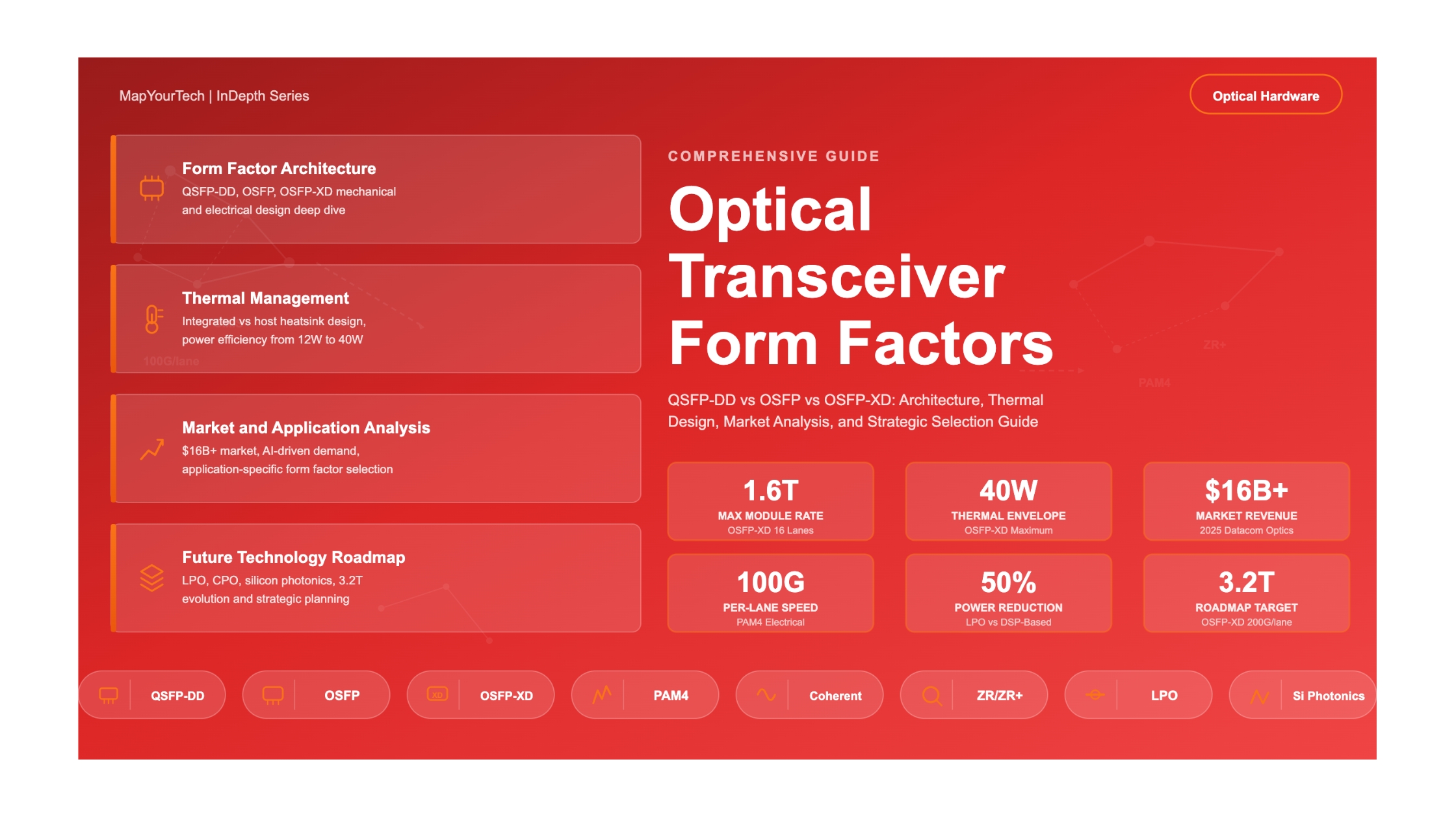

Understanding Optical Transceiver Form Factors: QSFP-DD, OSFP, OSFP-XD, and Beyond
A comprehensive guide to pluggable optical module form factors — from historical evolution through modern 400G/800G/1.6T designs and the road to 3.2T. Covering mechanical specifications, thermal architecture, electrical interfaces, and strategic selection criteria for data center architects and optical engineers.
1. Introduction
The optical transceiver has evolved from a simple photoelectric conversion component into the most strategically important element in modern network infrastructure. As data center traffic grows at compound annual rates exceeding 30%, driven by artificial intelligence (AI) training clusters, cloud computing, and hyperscale architectures, the pluggable optical module sits at the intersection of bandwidth scaling, power efficiency, and system economics. The choice of transceiver form factor — the physical, thermal, and electrical specification that defines how a module interfaces with network equipment — now directly influences rack-level power budgets, cooling architecture, port density, and multi-generational upgrade paths.
The datacom optical component market exceeded $16 billion in revenue in 2025, representing over 60% year-over-year growth. This surge was driven almost entirely by 800G optics deployment within AI training clusters, where the ratio of optical transceivers to Graphics Processing Units (GPUs) has increased to approximately six transceivers per GPU. In NVIDIA's GB300 NVL72 cluster architecture, optical transceivers account for roughly 60% of networking cost and 45% of total networking power. These numbers underscore a critical reality: the form factor of the optical module is no longer just a mechanical detail — it is a system-level architectural decision.
Two primary form factor families now dominate the 400G and 800G landscape: QSFP-DD (Quad Small Form-Factor Pluggable Double Density) and OSFP (Octal Small Form-Factor Pluggable). Each represents a different set of engineering trade-offs between backward compatibility, thermal headroom, port density, and future scalability. Meanwhile, the emergence of OSFP-XD (eXtra Dense) and next-generation concepts like Co-Packaged Optics (CPO) and Linear-Drive Pluggable Optics (LPO) are reshaping the boundaries of what pluggable modules can deliver.
This guide provides an exhaustive technical analysis of optical transceiver form factors — from the foundational GBIC and SFP through today's QSFP-DD800 and OSFP-XD, and forward into the 3.2T era. It is designed to serve as a reference resource for network architects, optical engineers, data center planners, and procurement teams making strategic decisions about their next-generation interconnect infrastructure.
2. Historical Context and Form Factor Evolution
2.1 The Foundation: From Fixed Optics to Hot-Pluggable Modules
The concept of a standardized, hot-swappable optical transceiver emerged in the mid-1990s as a direct response to the operational inflexibility of fixed optical interfaces. Before pluggable transceivers existed, network equipment shipped with permanently soldered optical components. Changing the optical interface — for example, switching from multimode fiber to single-mode fiber, or changing the reach from short-range to long-range — required replacing the entire line card or chassis module. This approach was expensive, wasteful, and operationally disruptive.
The Gigabit Interface Converter (GBIC), introduced in 1995 by the Small Form Factor Committee, was the industry's first widely adopted solution to this problem. GBIC modules were hot-swappable, SC-connector-based transceivers that supported Gigabit Ethernet and Fibre Channel at rates up to 2.5 Gb/s. While revolutionary for their time, GBICs were physically large — approximately 30 mm wide and 65 mm long — which severely limited the number of ports that could be fitted onto a line card. A typical 1U switch could accommodate only a handful of GBIC ports.
The industry recognized that miniaturization was essential to scaling port density. In 2001, the Small Form-Factor Pluggable (SFP) was introduced as a direct replacement for the GBIC. Often called "mini-GBIC," the SFP offered identical functionality in roughly half the physical volume. It used LC-type fiber connectors instead of the larger SC connectors, enabling significantly higher port densities. The SFP quickly became the dominant form factor for 1G Ethernet and 4G Fibre Channel applications, and it remains widely deployed today — a testament to the longevity of well-designed form factor standards.
2.2 The Race to 10G: Competing Approaches
The transition from 1G to 10G speeds in the early 2000s triggered a proliferation of competing form factors, each optimized for different market segments. The XENPAK (2001), X2 (2003), and XFP (2002) standards all targeted 10 Gigabit Ethernet. XENPAK was physically large and designed for initial market adoption when 10G components were expensive and power-hungry. X2 offered a smaller footprint — roughly half of XENPAK — while XFP (the "X" representing the Roman numeral 10) was protocol-independent and physically comparable to the SFP form factor, making it the most versatile of the 10G options.
However, the SFP+ specification, published in 2006, ultimately won the 10G form factor competition. SFP+ maintained the same physical dimensions as the original SFP while supporting data rates up to 16 Gb/s. Its backward compatibility with SFP cages and its compact size gave it decisive advantages in port density and deployment simplicity. The SFP+ approach of keeping the physical form factor constant while increasing the data rate per lane became a foundational design principle that would influence all subsequent form factor evolution.
Read the Full Analysis with Premium
The remaining 89% of this article — the design numbers, trade-offs and field guidance — is part of MapYourTech Premium, along with the full premium library, courses and professional tools.


