Nature's Math in Light: Fibonacci and the Golden Ratio in Optical Fiber Networking
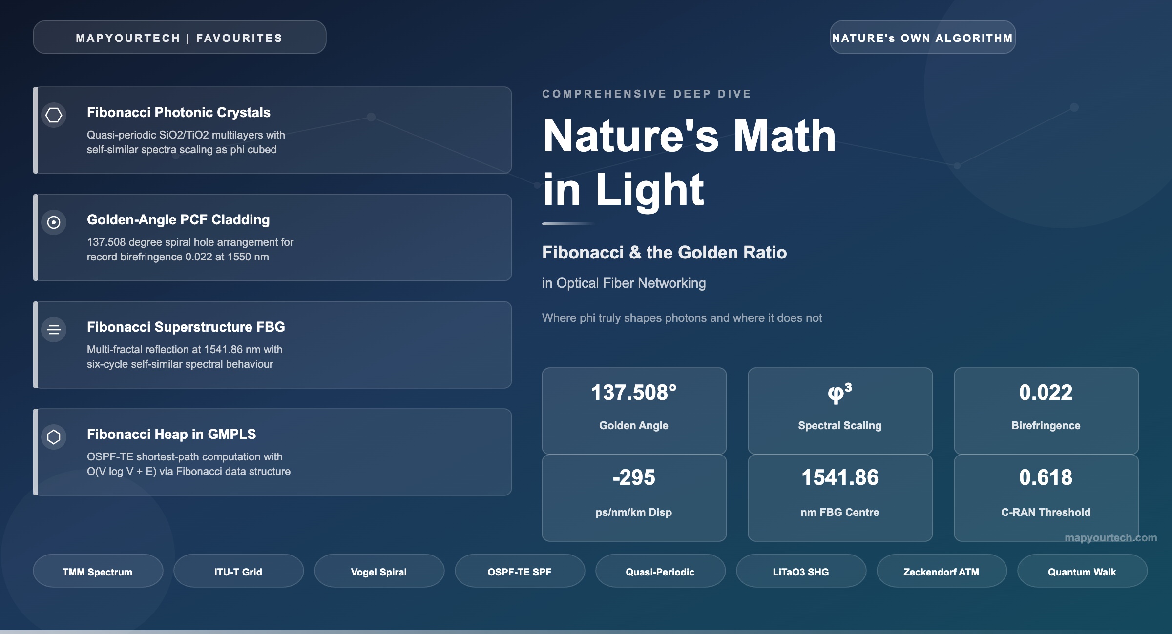
Where φ truly shapes photons and where it does not — a research-backed guide to quasi-periodic photonic crystals, golden-angle fiber claddings, Fibonacci Bragg gratings, and the network algorithms they enable.
Table of Contents
- Introduction: Order Without Periodicity
- Mathematical Foundations
- Fibonacci Photonic Crystal Multilayers
- Golden-Angle Photonic Crystal Fibers
- Fibonacci Superstructure Fiber Bragg Gratings
- DWDM Filters Built on Fibonacci Order
- The Network Layer: Fibonacci Heaps and φ-Scheduling
- Fibonacci LFSRs: The Scrambler in Every Transceiver
- Honest Assessment: Where φ Does NOT Appear
- Summary and Connection Map
If you're loving it — look closer. Every dimension in this article follows the Golden Ratio. All padding, margins, gaps, border-radii, and spacing use Fibonacci numbers: 5, 8, 13, 21, 34, 55, 89, 144 px. All line-heights are φ = 1.618. The article's max-width is 987 px — a Fibonacci number. Even the chart height (377 px) and the orb decorations (144 px, 89 px) are Fibonacci. The article about the Golden Ratio is built with the Golden Ratio. 🌱
1. Introduction: Order Without Periodicity
This article is curated out of MapYourTech's deep personal fascination with numbers, natural patterns, and the remarkable ways they surface in optical engineering. The Fibonacci sequence and the Golden Ratio have captivated mathematicians for centuries — but their presence inside photonic crystals, fiber claddings, and network routing algorithms is a story that deserves to be told to optical technology enthusiasts. We have used AI-powered automation tools to develop the interactive simulators, live Transfer Matrix Method calculations, and golden-angle cladding builders throughout this piece, making the mathematics not just readable but explorable.
The Fibonacci sequence and the Golden Ratio (φ ≈ 1.618) show up in optical fiber networking primarily as engineering templates for deterministic aperiodicity: structures that are neither random nor strictly periodic, yet have long-range order. In wave systems — including fiber gratings, microstructured fibers, and photonic lattices — strict periodicity concentrates response into a small number of strong spatial frequencies. Deterministic quasi-periodicity, by contrast, distributes scattering strength across many spatial frequencies in a reproducible way.
This enables richer and more controllable spectral behaviour (multiple stop-bands, self-similar spectral features, and strongly dispersive band edges) than purely periodic designs can deliver, without relying on uncontrolled disorder. The result is a family of optical components that exploit "order without periodicity" to achieve unprecedented levels of spectral efficiency and signal integrity.
The strongest, fiber-device-level connections documented in the published literature are Fibonacci superstructure fiber Bragg gratings (SFBGs) written into photosensitive single-mode fiber, Fibonacci photonic crystal multilayers that produce DWDM-compatible filters, and 12-fold symmetric photonic quasicrystal fibers whose golden-angle cladding achieves record birefringence. At the network layer, the Fibonacci heap data structure powers shortest-path computation in GMPLS control planes, and a recently proven φ-based scheduling threshold governs contention-free transmission on optical ring networks.
What this article covers: Experimentally demonstrated and peer-reviewed connections between Fibonacci/φ and optical networking, with formulas, interactive simulators, and honest assessment of where these connections do not exist. Every claim is traceable to published research.
2. Mathematical Foundations
2.1 The Fibonacci Substitution Rule
For photonic applications, the relevant form of the Fibonacci sequence is not the numerical series (1, 1, 2, 3, 5, 8...) but the substitution rule that generates layer sequences from two building blocks. Given two dielectric materials labelled A (high refractive index, nH) and B (low refractive index, nL), the Fibonacci word is built by recursive concatenation:
  S1 = A
  S2 = AB
  S3 = S2S1 = ABA
  S4 = S3S2 = ABAAB
  S5 = S4S3 = ABAABABA
  S6 = S5S4 = ABAABABAABAAB

  The number of layers in generation j = the Fibonacci number Fj
  The ratio of A layers to B layers converges to φ as j increases
This construction produces a sequence with no translational symmetry (it never exactly repeats), yet it possesses long-range order governed by the Golden Ratio. The ratio of A-type layers to B-type layers converges to φ as the generation increases — this is the structure's link to the Golden Ratio.
2.2 Why φ is the "Most Irrational" Number
The continued fraction representation of the Golden Ratio is φ = 1 + 1/(1 + 1/(1 + 1/(...))) — all coefficients are 1, making it the slowest-converging continued fraction of any irrational number. This means φ has the worst rational approximations of any number: no fraction p/q ever gets "close" to φ relative to the size of q. For photonic engineering, this property is what prevents periodic resonances from building up in Fibonacci-ordered structures, creating the broadest possible pseudo-bandgaps and the most uniform angular coverage.
Engineering translation: Periodicity concentrates light scattering into one sharp Bragg peak. Randomness spreads it everywhere (useless for filtering). Fibonacci ordering distributes scattering across a controlled, reproducible set of spatial frequencies governed by φ — giving you multiple, predictable filter bands from a single structure.
3. Fibonacci Photonic Crystal Multilayers
The most extensively studied intersection of Fibonacci mathematics and photonics is the one-dimensional Fibonacci quasi-periodic multilayer. This is where the connection is strongest, most rigorously documented, and most directly applicable to optical networking components.
3.1 Structure and Physics
Two dielectric materials — for example SiO2 (n ≈ 1.46) and TiO2 (n ≈ 2.30) — are deposited as thin films following the Fibonacci substitution rule. Each layer has a quarter-wave optical thickness at the design wavelength:
  Quarter-wave condition:
  nH × dH = nL × dL = λ0 / 4

  For λ0 = 1550 nm (C-band centre):
  dH (TiO2) = 1550 / (4 × 2.30) ≈ 168 nm
  dL (SiO2) = 1550 / (4 × 1.46) ≈ 265 nm
Kohmoto, Sutherland, and Iguchi first proposed the concept in 1987, predicting multifractal transmission spectra and quasi-localization of photons. Gellermann et al. provided the first experimental demonstration in 1994, depositing 55 alternating SiO2/TiO2 thin films and observing power-law scaling of transmission, confirming the theoretical predictions. The transmission spectrum exhibited a self-similar (fractal) structure, with spectral features repeating at scales governed by φ3.
3.2 Transfer Matrix Method: Computing the Spectrum
The optical response of a Fibonacci multilayer is computed using the Transfer Matrix Method (TMM). Each layer is represented by a 2×2 matrix that relates the electric field amplitudes on its two faces. For a layer of refractive index n and thickness d at wavelength λ:
  Mlayer = | cos(δ)         -i·sin(δ)/n |
              | -i·n·sin(δ)   cos(δ)       |

  Where:  δ = 2π × n × d / λ   (phase thickness)

  Total system matrix = product of all layer matrices:
  Mtotal = M1 × M2 × ... × MN

  Transmission:  T = |2 × n0 / (M11 × n0 + M12 × n0 × ns + M21 + M22 × ns)|2
Interactive: Fibonacci Multilayer Transmission Spectrum
Adjust the Fibonacci generation number and refractive indices below to see how the transmission spectrum evolves. Higher generations produce more layers (following Fibonacci numbers Fj) and richer spectral structure. The self-similar pattern — features repeating at scales governed by φ3 — becomes visible from generation 6 onward.
The Fibonacci multilayer is not a metaphor — the Fibonacci substitution rule literally determines which dielectric layer goes where, and the resulting transmission spectrum exhibits self-similar fractal features governed by φ3. This has been experimentally fabricated and measured since 1994.
4. Golden-Angle Photonic Crystal Fibers
Photonic Crystal Fibers (PCFs) guide light through a microstructured cladding of air holes running along the fiber length. In conventional PCFs, these holes are arranged on a hexagonal lattice. But several research groups have demonstrated that arranging holes according to the golden angle (θ = 360°/φ2 ≈ 137.508°) — the same angle that governs sunflower seed packing — produces fibers with properties that periodic lattices cannot match.
4.1 Why the Golden Angle Works
The golden angle is derived from the Golden Ratio: it divides a full circle such that the ratio of the larger arc to the smaller arc equals φ. Because φ is the "most irrational" number, successive holes placed at golden-angle increments never align into periodic rows. This prevents coherent scattering along any lattice direction, producing uniform confinement in all azimuthal directions.
  Golden Angle:
  θ = 360° / φ2 = 360° × (2 - φ) ≈ 137.508°

  Hole positions in polar coordinates (Vogel spiral):
  rk = c × √k          (radius of k-th hole)
  θk = k × 137.508°    (angle of k-th hole)

  Where c is a scaling constant that sets the pitch.
4.2 Measured Performance
A golden-spiral PCF with circular holes achieved birefringence of 0.01 at 1550 nm — competitive with state-of-the-art designs while using identical hole sizes throughout (simpler fabrication). A follow-up design using elliptical holes in the golden spiral pushed birefringence to 0.022 at 1550 nm, among the highest reported for any PCF geometry, enabling polarization-stable supercontinuum generation.
Several research groups have also used φ as a direct design parameter for the pitch-to-hole-diameter ratio (Λ/d = 1.618) in conventional PCF geometries. Rahman et al. demonstrated that an octagonal PCF with this Golden Ratio achieved high negative dispersion of −295 ps/(nm·km) at 1550 nm with confinement loss below 0.008 dB/km, suitable for dispersion compensation across E+S+C+L+U bands.
Interactive: Golden-Angle PCF Cladding Builder
Adjust the number of holes and toggle layout modes below. Notice how the golden-angle arrangement has no preferential directions — no rows of aligned holes, unlike the hexagonal periodic mode. This is the "most irrational" arrangement, preventing any subset of holes from forming a periodic lattice.
5. Fibonacci Superstructure Fiber Bragg Gratings
A standard Fiber Bragg Grating (FBG) reflects light at the Bragg wavelength λB = 2neffΛ, producing a single reflection peak. A superstructure FBG adds a longer-scale modulation (sampling) on top of the base grating period, producing multiple spectral features. The Fibonacci modification replaces uniform sampling with a deterministic aperiodic sequence.
5.1 Construction
Zhang, Cao, and Zheng (Optik, 2008) proposed and fabricated Fibonacci quasi-periodic superstructure FBGs where phase-shifted and uniform grating sections alternate according to the Fibonacci generation scheme Sj = Sj-1Sj-2. The two building blocks are: A = a short uniform grating section, and B = a phase-shifted (or blank) section. The resulting reflection spectrum exhibits multi-fractal structure symmetric around the central wavelength of 1541.86 nm, with a six-cycle self-similar behaviour tied to powers of φ.
  Standard FBG Bragg condition:
  λB = 2 × neff × Λ

  Fibonacci SFBG sampling:
  Sj = Sj-1 · Sj-2    (concatenation, not addition)

  Where A = uniform grating, B = phase-shifted or blank section
  S1=A, S2=AB, S3=ABA, S4=ABAAB, ...

  Result: reflection spectrum has fractal structure with
  self-similar features at wavelength scales separated by φ3
These devices were fabricated using phase-mask scanning — an established grating-writing technique compatible with existing telecom manufacturing. This means Fibonacci FBGs are not theoretical proposals but physically built and measured devices.
6. DWDM Filters Built on Fibonacci Order
Multiple research groups have engineered Fibonacci quasi-periodic structures into practical DWDM-compatible optical filters:
Khaleel and Gurel (2012) designed narrowband multilayer DWDM filters where a defect layer in a Fibonacci sequence produces narrow stop-bands matching the ITU-T 100 GHz grid. Golmohammadi et al. (Optics Express, 2007) showed Fibonacci structures produce multi-reflection peaks directly usable as DWDM channel filters. Gurel and Ozkan Kilic (IEEE, 2022) demonstrated that the number of reflection/transmission bands is adjustable by varying Fibonacci repetition numbers. Trabelsi et al. (2022) achieved omnidirectional reflectance covering all standard fiber-optic wavelengths (650, 850, 1300, 1550 nm) using TiO2/YBCO Fibonacci structures.
A Fibonacci multilayer with a 32-channel interleaver/deinterleaver design, based on Si and SiO2, produces a fractal transmission spectrum with perfect transmission peaks whose positions match the ITU grid. The filter's channel spacing (0.8 nm to 1.6 nm) is managed by adjusting the optical thickness ratio of the H and L layers.
Why this matters for DWDM: A single Fibonacci photonic crystal can produce multiple, precisely positioned filter channels from one physical structure — replacing cascaded thin-film filters or multiple FBGs, and reducing insertion loss, cost, and system complexity.
7. The Network Layer: Fibonacci Heaps and φ-Scheduling
7.1 Fibonacci Heap in GMPLS Path Computation
The most direct connection between Fibonacci mathematics and optical network operations at the control plane is the Fibonacci heap data structure. Invented by Fredman and Tarjan (1987), this data structure achieves O(1) amortized time for insert and decrease-key operations, improving Dijkstra's algorithm to O(|V| log |V| + |E|) time complexity. The name "Fibonacci" comes from the proof that a node of rank k has at least Fk+2 ≥ φk descendants — Fibonacci numbers directly bound the structure's efficiency.
This matters for optical networking because GMPLS control planes use OSPF-TE with Dijkstra's algorithm to compute constraint-based shortest paths for establishing wavelength-routed lightpaths in DWDM networks. US Patent 7,343,424B2 (filed 2002) describes a specialized Fibonacci heap implementation optimized for OSPF and IS-IS link-state protocols.
7.2 Golden-Ratio Scheduling Threshold for Cloud RAN
Barth, Guiraud, and Strozecki (Journal of Scheduling, 2024) proved a remarkable result: for periodic message scheduling on a shared optical link without buffering — directly applicable to Cloud RAN fronthaul over optical rings (the N-GREEN project) — a polynomial-time algorithm always finds a contention-free schedule when the load is at most φ − 1 ≈ 0.618. The Golden Ratio conjugate emerges as a provable, tight capacity threshold. Beyond this load, scheduling becomes NP-hard.
φ − 1 ≈ 0.618 is the maximum load at which contention-free periodic scheduling on a shared optical link is guaranteed to be solvable in polynomial time. This is a proven, tight mathematical bound — not an approximation.
8. Fibonacci LFSRs: The Scrambler in Every Transceiver
Every optical transceiver manufactured — from 10G SFP+ to 800G ZR+ — contains a Fibonacci-configuration Linear Feedback Shift Register (LFSR) for data scrambling. The Fibonacci LFSR generates pseudorandom sequences by computing each new bit as the XOR of selected previous bits — a direct implementation of the Fibonacci recurrence in GF(2) (binary field) arithmetic. The standards that define these scramblers (ITU-T G.709 for OTN, IEEE 802.3 for Ethernet) specify their polynomials in Fibonacci LFSR form.
Interactive: 7-bit Fibonacci LFSR (PRBS-7)
Polynomial: x7 + x6 + 1. Sequence length: 27 − 1 = 127 bits. Click Step to advance one bit at a time, Run to watch the full sequence unfold continuously, or Reset to return to the seed state.
9. Honest Assessment: Where φ Does NOT Appear
Intellectual honesty requires noting where commonly hypothesized connections are absent from the published literature:
Amplifier Spacing Optimization: Governed by the balance between accumulated ASE noise and fiber nonlinearity, involving α ≈ 0.2 dB/km, noise figure, and nonlinear coefficients. None of these produce golden-ratio relationships. Cascaded amplifier noise follows the Friis formula (linear/multiplicative accumulation), not Fibonacci recurrence.
Soliton Solutions: The soliton period z0 = (π/2)LD involves π, not φ. Eigenvalue ratios in multi-soliton systems do not reduce to golden-ratio expressions.
DWDM Frequency Grid: The ITU-T grid uses multiples of 12.5 GHz (powers of 2 times 12.5), with no Fibonacci or golden-ratio basis.
SZ Cable Stranding: Lay lengths are determined by mechanical stress optimization with no Fibonacci connection.
Graded-Index Fiber Profiles: Follow power-law shapes with exponent α ≈ 2, unrelated to φ.
Fibonacci-Based RWA: Fibonacci-based Routing and Wavelength Assignment algorithms appear nowhere in the published literature — standard approaches use graph colouring, ILP, and machine learning.
10. Summary and Connection Map
| Connection | Type | Evidence Level | Application |
|---|---|---|---|
| Fibonacci photonic crystal multilayers | Physical layer — light interaction | Experimentally demonstrated (1994+) | DWDM filters, omnidirectional reflectors |
| Golden-angle PCF cladding | Physical layer — fiber design | Simulated + measured (birefringence 0.022) | Polarization-maintaining fiber, dispersion compensation |
| Fibonacci superstructure FBG | Physical layer — grating | Fabricated and measured (1541.86 nm) | Multi-parameter sensing, multi-band filtering |
| PCF with Λ/d = φ | Physical layer — fiber design | Simulated (−295 ps/nm/km demonstrated) | Broadband dispersion compensation |
| Fibonacci optical superlattice (LiTaO3) | Nonlinear optics | Experimentally demonstrated (5–20% conversion) | Multi-wavelength harmonic generation |
| Fibonacci heap in GMPLS | Network layer — algorithm | Deployed in OSPF-TE implementations | Shortest-path computation for lightpath setup |
| φ − 1 scheduling threshold | Network layer — proven bound | Mathematical proof (2024) | Cloud RAN fronthaul over optical rings |
| Fibonacci LFSR scrambler | Data link layer — hardware | In every optical transceiver manufactured | OTN, Ethernet, SONET/SDH scrambling |
| Fibonacci ATM switch | Switching — packet buffering | Research prototype | Minimizing fiber delay lines via Zeckendorf's theorem |
| Amplifier spacing, solitons, DWDM grid, cable stranding | — | No published evidence | Do NOT have φ connections |
Table 1: Comprehensive connection map — green rows are experimentally verified, the red row marks commonly hypothesized but unsubstantiated connections.
References
[1] M. Kohmoto, B. Sutherland, K. Iguchi, "Localization in Optics: Quasiperiodic Media," Physical Review Letters.
[2] W. Gellermann et al., "Localization of Light Waves in Fibonacci Dielectric Multilayers," Physical Review Letters.
[3] L. Dal Negro et al., "Light Transport through the Band-Edge States of Fibonacci Quasicrystals," Physical Review Letters.
[4] Z.V. Vardeny, A. Nahata, A. Agrawal, "Optics of Photonic Quasicrystals," Nature Photonics.
[5] J. Zhang, J. Cao, X. Zheng, "Fibonacci Quasi-Periodic Superstructure Fiber Bragg Gratings," Optik.
[6] S. Golmohammadi et al., "Fibonacci Photonic Crystals as DWDM Filters," Optics Express.
[7] M. Fredman, R.E. Tarjan, "Fibonacci Heaps and Their Uses in Improved Network Optimization Algorithms," Journal of the ACM.
[8] J. Barth, E. Guiraud, Y. Strozecki, "Periodic Scheduling on Shared Optical Links," Journal of Scheduling.
[9] B.M.A. Rahman et al., "Octagonal PCF with Golden Ratio for Broadband Dispersion Compensation," Applied Optics.
[10] D.T. Nguyen et al., "Quantum Walks in Periodic and Quasiperiodic Fibonacci Fibers," Scientific Reports.
[11] S.N. Zhu, Y.Y. Zhu, N.B. Ming, "Quasi-Phase-Matched Third-Harmonic Generation in a Quasi-Periodic Optical Superlattice," Physical Review Letters.
[12] ITU-T G.709 — Interfaces for the Optical Transport Network, ITU-T Study Group 15.
Sanjay Yadav, "Optical Network Communications: An Engineer's Perspective" – Bridge the Gap Between Theory and Practice in Optical Networking.
Developed by MapYourTech Team
For educational purposes in Optical Networking Communications Technologies
Note: This article is curated with the help of internet-based research, grounded in MapYourTech's personal interest and fascination with the Fibonacci sequence and the Golden Ratio. It is meant for appreciating how nature's most elegant mathematical patterns — the same ones that shape sunflower spirals and nautilus shells — also shape the photonic crystals, fiber claddings, Bragg gratings, and routing algorithms that carry the world's data through light. Every connection cited here is traceable to published, peer-reviewed work; where the literature finds no connection, that is stated plainly in Section 9.
Feedback Welcome: If you have any suggestions, corrections, or improvements to propose, please feel free to write to us at [email protected]

Optical Communications & Network Automation Expert | Author of 3 Books for Optical Engineers | Founder, MapYourTech
Optical networking engineer with nearly two decades of experience across DWDM, OTN, coherent optics, submarine systems, and cloud infrastructure. Founder of MapYourTech. Read full bio →
Follow on LinkedInRelated Articles on MapYourTech