
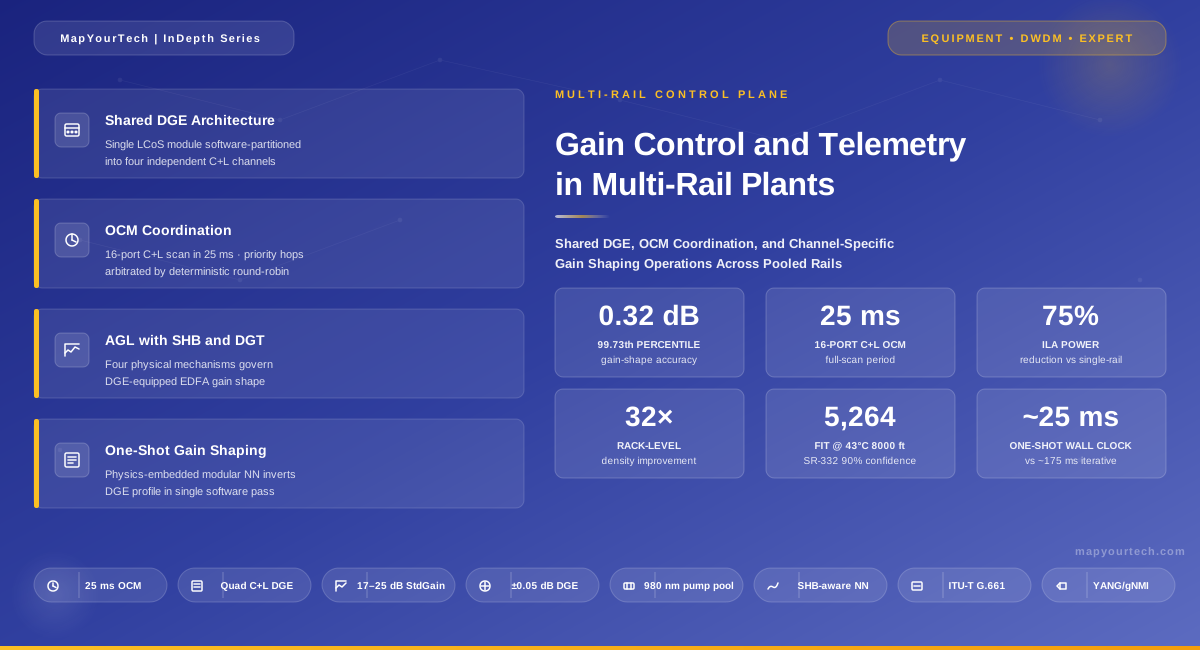
Gain Control and Telemetry in Multi-Rail Plants: Shared DGE, OCM Coordination, and Channel-Specific Gain Shaping
Multi-rail amplifier plants pool the slow, expensive parts of an EDFA — pump lasers, dynamic gain equalizers, optical channel monitors — across several parallel rails. Once shared, those resources become a contested control bottleneck. This article works through the physics, the timing, and the model architecture that move shared DGE/OCM operations from the hundreds-of-milliseconds regime of iterative refinement into the millisecond regime of one-shot, physics-embedded gain shaping.
1. Abstract and engineering summary
Multi-rail optical line systems consolidate amplification, monitoring, and gain equalization for several parallel fiber pairs into a single shelf. The motivation is purely economic and physical: an AI-era backbone may need hundreds of fiber pairs between two sites, and provisioning each pair with a dedicated chassis would exceed the power, space, and cooling budget of every legacy ILA hut on the route. Pooling is the answer. Public industry data on rail-pooled architectures describes up to 32× rack-level density improvement and up to 75% ILA power reduction relative to single-rail designs. Recent component-level work has demonstrated arrayed C+L DGE modules that fold four to eight discrete devices into one LCoS package, and 16-port C+L OCM modules with 25 ms full-scan time across all ports.
The architectural cost of pooling is paid in the control plane. When one DGE serves four rails and one OCM monitors sixteen rail-band combinations on a 25 ms scan budget, the per-rail control loop no longer enjoys exclusive access to its instrumentation. A naive iterative gain-shaping loop that closes through OCM measurement and DGE reconfiguration on every step accumulates serialization delay across rails, amplifies ±0.05 dB DGE setting noise into convergence stalls, and stresses the physical hardware with retries. Recent research published in the peer-reviewed optical communications literature demonstrates a physics-embedded modular neural-network model that calculates the required DGE attenuation profile in one shot — collapsing channel-specific gain shaping from a multi-step feedback chain into a single-pass calculation with 0.32 dB accuracy at the 99.73th percentile and 0.4 dB extreme-case error across 1,000 randomly selected target gain spectra.
This article works through that transition end-to-end. Section 2 establishes why multi-rail's economics force resource sharing. Section 3 traces the variable-gain EDFA-with-DGE concept from its 2002 origin to its 2026 productization. Section 4 covers the four physical mechanisms a real shared-DGE EDFA must handle simultaneously: spectral hole burning, average gain locking, the linear combination law of DGE attenuation, and dynamic gain tilt under varying inversion. Section 5 lays out the architecture of a four-rail amplifier with a single quad C+L DGE and a single 16-port OCM. Section 6 develops the gain-prediction mathematics and the inversion algorithm that solves for the DGE profile required to meet a target gain spectrum. Section 7 quantifies the control-loop timing budget — OCM scan time, computation latency, liquid-crystal response, and serialization across rails. Section 8 benchmarks the physics-embedded one-shot model against pure data-driven and pure iterative approaches. Section 9 walks through three operational cases. Section 10 contrasts iterative refinement with model-driven control. Section 11 covers limitations, including correlated failure modes when shared hardware fails. Section 12 looks at digital twins, learned controllers, and sub-millisecond gain shaping. The reference section preserves the public sources used.
Takeaway: Multi-rail's value proposition is sub-linear scaling of cost, power, and space. The shared-DGE/shared-OCM design achieves that by serializing control. Physics-embedded one-shot modelling is the technique that keeps per-rail control fast despite the serialization, replacing iterative OCM-DGE refinement with single-pass computation that delivers 99.73th-percentile gain-shape accuracy of 0.32 dB.
2. Introduction: why multi-rail forces shared control
An ILA hut along a North American long-haul route carries a fixed envelope of constraints inherited from its physical history. Many were built decades ago alongside roads and railroad rights-of-way. They are physically small. The available DC feed is bounded — 3000 W per shelf is a typical ceiling. The depth available for rack equipment is often sub-300 mm. The high-temperature pump-laser specifications must accommodate altitude up to several thousand feet and ambient excursions that push uncooled 980 nm pumps to their thermal limits. Within that envelope, an operator wanting to move from a single-rail ILA carrying ~50 Tb/s on a C+L pair to an AI-scale 20 Pb/s site needs roughly four hundred times the per-site capacity. Single-rail scaling does not fit.
The industry's response has been to redefine the unit of scale. Rather than treating the wavelength as the fundamental capacity quantum and adding fiber pairs incrementally, the multi-rail architecture treats a fully filled fiber pair as the basic capacity unit and packs multiple rails into the same shelf. Independent equipment-supplier programmes have produced parallel public expressions of the same underlying principle — multi-rail line-system platforms with shared resource pooling for efficient optical transport. Both report sub-linear scaling — public data cites up to 75% power reduction and 32× density improvement at the rack level, claiming up to 128 rails per rack against the 4 rails per rack of legacy single-rail ILA designs.
The sub-linear scaling does not come for free. It comes from sharing. Specifically, it comes from identifying every component in a single-rail amplifier whose physical constraint allows it to serve more than one rail simultaneously, and consolidating those components into pooled modules. A 980 nm pump laser running uncooled at ~700 mW per chip is shared across multiple rails through a passive splitter — a dual-chip uncooled pump-laser module with combined output to a 1×N splitter is the canonical example. A liquid-crystal-on-silicon (LCoS) wavelength selective switch, sized for one C+L band, can be partitioned in software to serve four independent C+L DGE channels — the quad C+L DGE module condenses four discrete devices into one. An optical channel monitor sized for sixteen ports can scan all sixteen on a 25 ms cycle and deliver per-port spectra to whichever rail's controller asks first. The economic dividend of pooling is direct: every shared component is a deleted line card, a deleted optical assembly, a deleted thermal load.
Read the Full Analysis with Premium
The remaining 88% of this article — the design numbers, trade-offs and field guidance — is part of MapYourTech Premium, along with the full premium library, courses and professional tools.
You May Also Like

-
Free
-
September 4, 2026

-
Premium
-
September 4, 2026

-
Premium
-
September 4, 2026