
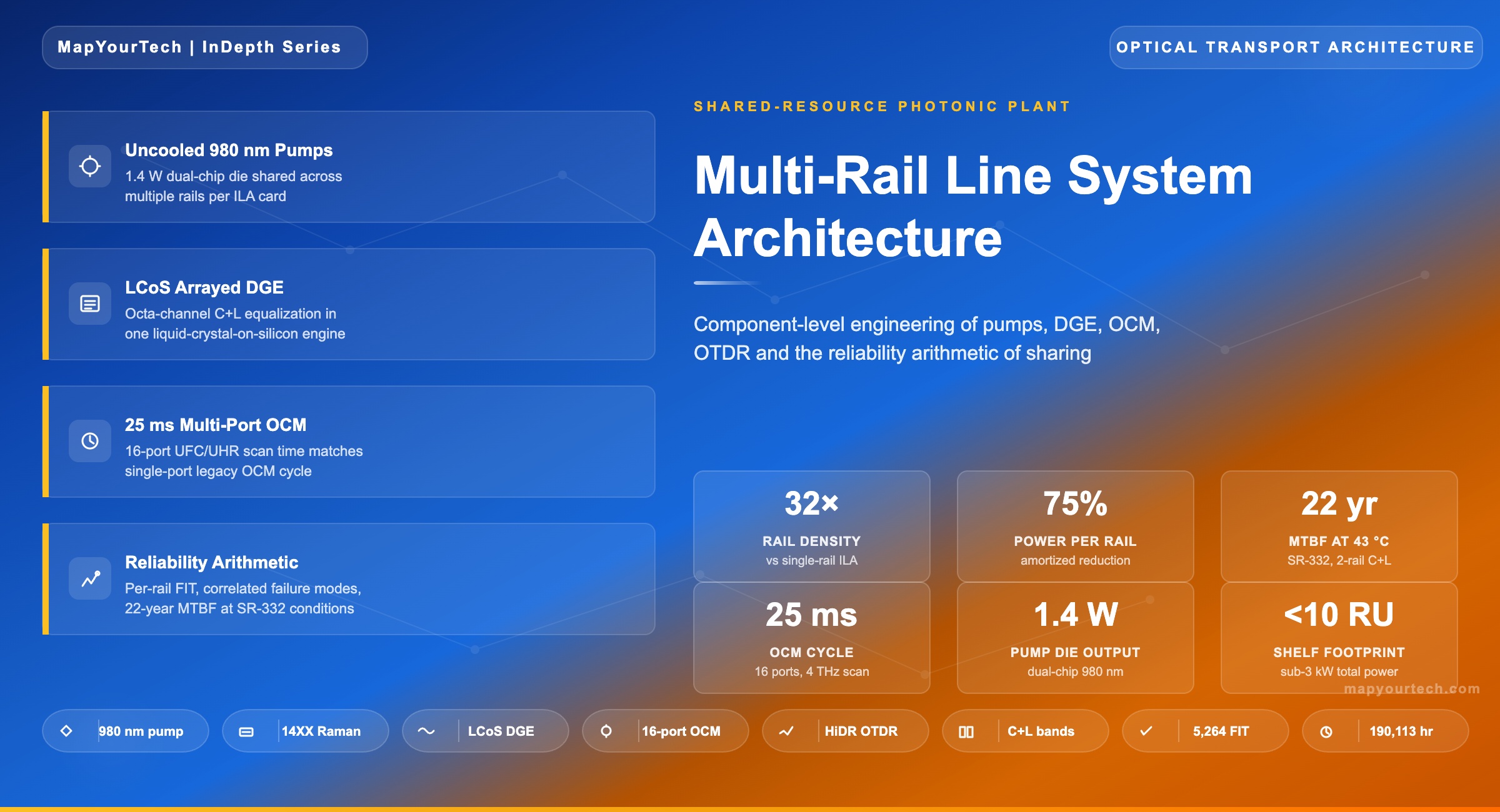
Multi-Rail Line System Architecture: Component-Level Engineering of a Shared-Resource Photonic Plant
A component-by-component deep dive into how multi-rail line systems collapse the per-fiber-pair photonic plant onto shared hardware. Covers uncooled high-power 980 nm pumps, multi-chip 14XX nm pumps, LCoS-based arrayed dynamic gain equalisers, multi-port C+L optical channel monitors with 25 ms scan time, consolidated multi-port OTDR, and parallel-serial passive integration — for each block, the physics, the sharing scheme, the per-rail isolation requirement, and the resulting reliability arithmetic.
1. Introduction and System Context
For two decades the photonic line system was sized around a single fiber pair. One pump laser per stage, one dynamic gain equaliser per amplifier, one optical channel monitor per node, one OTDR per inspection point. Capacity was added one wavelength at a time inside the C-band, then extended into the L-band — and when the bands were full, operators lit a second fiber pair and replicated the photonic plant alongside the first.
That model has reached the wall set by the Shannon limit. With 16QAM at practical OSNR margins, a single C+L fiber pair delivers approximately 50 Tb/s. Distributed AI training clusters now demand tens of petabits per second between sites, often across hundreds of fiber pairs along the same route. Replicating a single-rail line system 100 or 200 times over is not a refinement — it would consume site real estate, hut power feeds, and air-conditioning capacity that simply do not exist.
The multi-rail line system — sometimes labelled hyper-rail — is the photonic-layer answer. It treats the fully filled fiber pair as the new unit of scale and integrates the optical components needed to manage multiple fiber pairs onto a single line card. Industry-published figures for first-generation multi-rail platforms cite rack-level density improvements around 32×, per-rail power reductions of up to 75%, and rack-space reductions of approximately 80% per rail compared to single-rail equivalents.
The architectural shift looks simple from the outside: put more rails in less space. The engineering inside each line card is anything but simple. Sharing a pump laser across rails forces a correlated failure mode that per-rail systems do not have. Sharing a single LCoS array across multiple DGE channels forces tighter pixel-resolution requirements and new crosstalk-isolation budgets. Sharing one OCM across 16 ports forces a 25 ms scan-time target so per-rail telemetry refresh rates remain useful for closed-loop control. And sharing an OTDR across multiple fibers requires a high-dynamic-range sequenced architecture that does not interfere with live traffic on the rails it is not measuring.
This article walks through each of those shared blocks in turn. For every one, it answers four questions:
- Physics. What does this block do, mechanistically, and why is it needed?
- Sharing scheme. Which physical resource is pooled, and how is that pool partitioned among rails?
- Per-rail isolation requirement. What stops one rail from interfering with another inside the shared block?
- Reliability arithmetic. What is the resulting failure-impact distribution, and how does it compare to the single-rail baseline?
The reader who finishes this article should be able to size a multi-rail line card from first principles, identify which of its components are correlated-failure liabilities, and know which engineering levers a vendor pulls to keep per-rail performance within standard ITU-T budgets while still hitting the 75% power-saving target. For the broader system context — why hyperscale AI traffic is forcing this architectural shift in the first place — the companion article on the architectural response to the AI-driven fiber density problem provides the high-level framing that this deep dive complements.
Scope note. This article is component-level. It assumes familiarity with EDFA operation, ROADM colorless-directionless-contentionless behaviour, OTN frame structure, and coherent transmission engineering. Where these prerequisites are touched, the explanation stays anchored to their consequence inside the shared-resource photonic plant rather than restating the underlying theory.
2. Anatomy of a Single-Rail ILA
To understand what gets shared, the starting point is what a conventional single-rail in-line amplifier (ILA) actually contains. An ILA exists at intermediate sites along a long-haul or DCI route, typically every 60 to 100 km, where the accumulated span loss has eroded enough of the optical signal that further propagation without amplification would push the OSNR below the receiver threshold for the deployed modulation format.
For a single C+L fiber pair, the ILA hardware breakdown is:
Active gain stage
- Pre-amplifier EDFA with its 980 nm pump laser, erbium-doped fiber spool, pump/signal WDM coupler, optical isolators on input and output, and a gain-flattening filter (GFF).
- Booster EDFA with a higher-power pump (often 14XX nm forward-pumped or 980 nm dual-pumped), its own EDF, isolators, and GFF.
- Mid-stage variable optical attenuator (VOA) or dynamic gain equaliser to flatten the spectral profile across the amplified band.
- For C+L systems: the entire chain is duplicated band-by-band, with C/L band splitters and combiners at the chassis edges.
Optical management functions
- Dynamic gain equaliser (DGE) — a wavelength selective switch (WSS) module built on liquid crystal on silicon (LCOS), used here in equalisation mode, attenuating individual frequency slices to flatten the post-amplifier spectrum.
- Optical channel monitor (OCM) — a tunable filter or spectrometer that measures per-channel power across the band, providing the closed-loop feedback signal for the DGE.
- Optical time-domain reflectometer (OTDR) — used during commissioning and when faults are suspected to localise fiber events along the span.
Per-fiber passives
- Optical isolators on input and output of every active stage.
- WDM couplers to combine pump and signal into the EDF.
- GFFs matched to the EDF gain profile and operating average inversion.
- C/L band splitters and combiners.
- Tap couplers (typically 1% to 5%) feeding the OCM and supervisory ports.
Electronic and mechanical infrastructure
- Pump laser drivers, automatic gain control (AGC) and automatic power control (APC) loops, temperature sensors and compensation circuits.
- Thermo-electric coolers (TECs) on the pump laser for cooled designs.
- Local controller running the gain-flattening algorithm, telemetry collection, and SNMP/NETCONF interface.
- Power-supply and DC distribution sized for the worst-case combined dissipation.
- Mechanical packaging: line card, faceplate connectors, heat-sinks, fans.
Every one of these blocks is replicated, in a single-rail line system, for every fiber pair the operator wants to light. Two fiber pairs equals two complete copies. Sixteen fiber pairs equals sixteen complete copies. The replicas occupy independent slots in the chassis, draw independent DC power, and run independent control loops.
The empirical observation that drives the multi-rail architecture is this: most of those replicated blocks do not actually need to be physically tied to a specific fiber pair. Only the components that physically carry that pair's optical signals — the EDF spool itself, its WDM coupler that injects pump light, and the input/output isolators that protect the gain medium — must remain per-rail. Everything else is candidate for sharing.
Read the Full Analysis with Premium
The remaining 88% of this article — the design numbers, trade-offs and field guidance — is part of MapYourTech Premium, along with the full premium library, courses and professional tools.
You May Also Like

-
Free
-
September 4, 2026

-
Premium
-
September 4, 2026

-
Premium
-
September 4, 2026