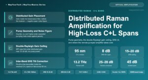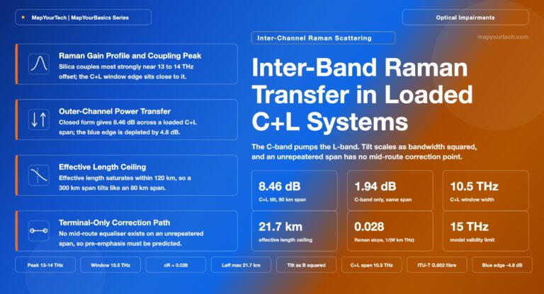
Optical Line Systems ·
Multi-Rail Line Systems:
Architectural Response to the AI-Driven Fiber Density Problem
Conventional optical line systems operate on a one-to-one principle: one chassis, one fiber pair. As hyperscale AI fabrics push required inter-data-center fiber pair counts into the hundreds, that architecture no longer works at intermediate line amplification sites. Multi-rail line systems address this by integrating the amplification and optical management of multiple parallel fiber pairs — rails — into shared hardware, converting linear per-rail cost and power scaling into a sub-linear trajectory.
1. Introduction
Optical transport line systems have historically operated on a one-to-one assumption: one chassis manages one fiber pair. Whether a ROADM node, an inline amplifier, or a terminal multiplexer, the hardware unit of management has always been the individual fiber pair. That assumption held when fiber pair counts between any two locations could be counted in the single digits. It breaks when the required fiber pair count reaches several hundred.
That is precisely where AI-driven scale-across networks are going. Distributed AI training and inference demand inter-data-center connectivity at petabit scale. The Shannon Limit caps the theoretical maximum capacity of a single fiber pair at approximately 50 Tb/s using 16QAM modulation across the combined C and L optical bands. Meeting aggregate throughput requirements measured in tens or hundreds of petabits therefore requires lighting up very large numbers of fiber pairs in parallel. There is no spectral efficiency improvement on the horizon that changes this arithmetic — the Shannon Limit is a physical ceiling, not an engineering target that future DSP generations will surpass.
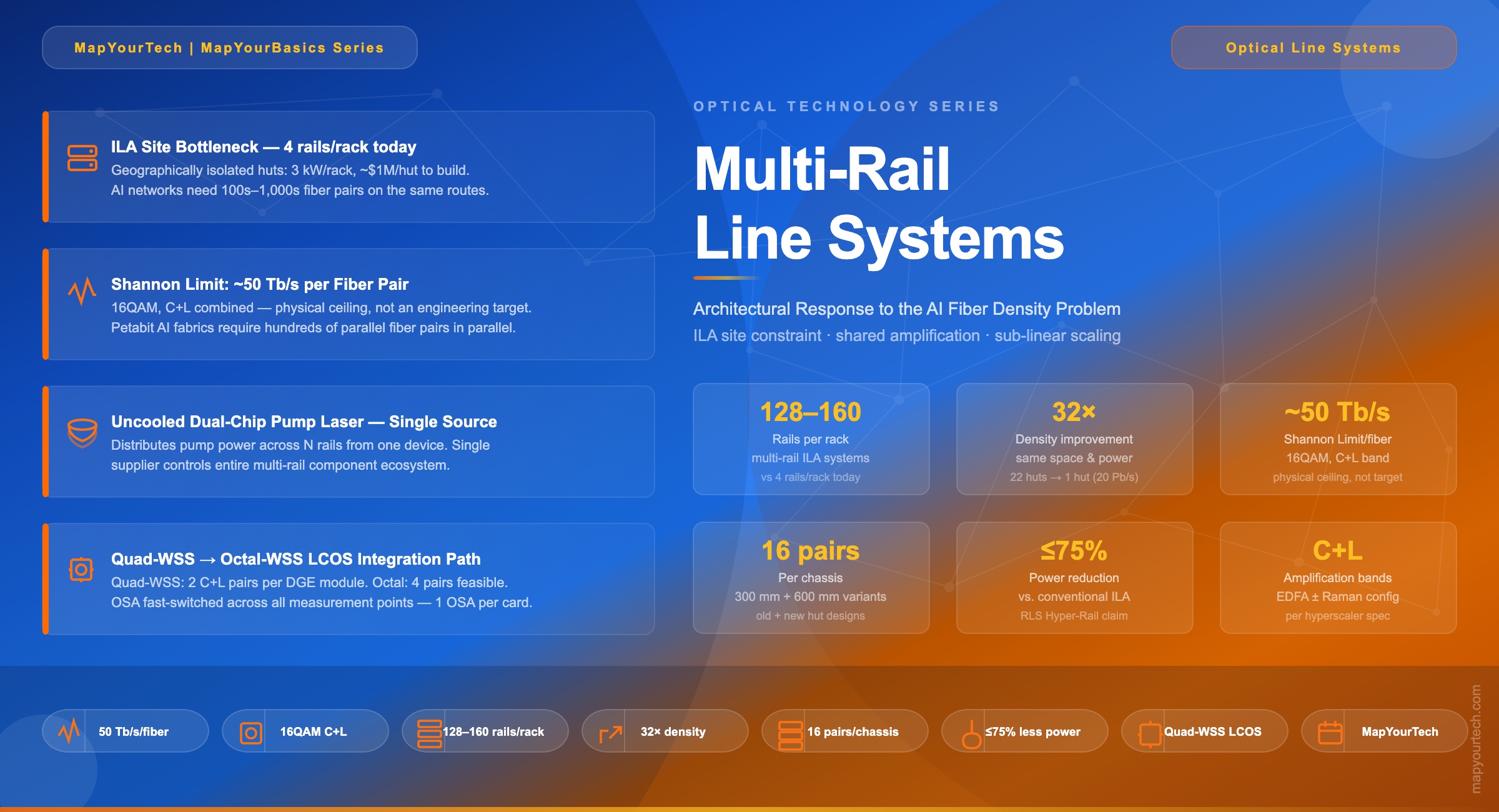
The hardware consequence of that arithmetic is a fiber pair count per inter-data-center route that current amplification infrastructure cannot accommodate within existing ILA site envelopes. Multi-rail line systems — announced by Ciena, Cisco, and Nokia at OFC 2026 — are the architectural response to that constraint, and represent a significant departure from how terrestrial optical line systems have been designed for the past two decades.
2. The ILA Site Constraint
The fiber pair count problem does not manifest at the data center itself. Scale-across links under approximately 150 km do not require intermediate line amplification — signal launch power and receiver sensitivity are sufficient to close the link over a single optical span, with all transmission equipment resident within the data center facility. The first wave of AI backbone deployments falls into this category: geographically proximate data centers on single-span routes where space and power are constrained but not a structural barrier.
The constraint becomes acute at ILA sites on longer inter-regional routes. ILA huts along North American terrestrial corridors were built decades ago along roadsides and railroad rights-of-way. They are physically small. A typical ILA site provides a handful of equipment racks at approximately 3 kW per rack. With conventional line systems delivering roughly 4 fiber pair rails per rack, a four-rack ILA hut accommodates 16 rails total.
Running that against AI-scale requirements makes the problem explicit. A 20 Pb/s inter-data-center backbone route requires on the order of 400 fiber pairs. At 4 rails per rack, that is 100 racks. At 3 kW per rack, that is 300 kW of amplifier power at a single ILA site — an order of magnitude beyond what existing hut infrastructure supports. Constructing new ILA huts at roughly $1M per site, multiplied across thousands of locations on key AI backbone routes, is neither economically viable nor feasible within the timeframe of AI infrastructure build-out. The amplification capacity required for AI-scale inter-regional networks must fit into the existing ILA physical envelope. Multi-rail architecture is the mechanism for achieving that.
The Scale Problem — Numbers That Define the Constraint
Figure 2: Typical long-haul fiber system topology — ILA sites spaced ~80 km apart, geographically isolated, power constrained at 3 kW/rack, currently supporting only 4 fiber pair rails per rack. AI-driven routes require 100s–1,000s of fiber pairs across the same infrastructure.
Figure 3: The 20 Pb/s AI example — conventional technology requires 22 separate ILA huts; multi-rail hyper-rail achieves the same capacity in 1 hut with 128 rails per rack, same space and power envelope, and up to 75% power reduction. Source: Ciena OFC 2026.
3. Multi-Rail Architecture — Definition and Structural Logic
A multi-rail line system integrates the transmission infrastructure of N parallel fiber pairs — referred to as rails — into a single managed platform that shares key hardware across all rails rather than replicating that hardware per rail. The name derives directly from the spatial analogy: multiple parallel fiber pair transmission paths managed as a single system entity.
Multi-Rail = N fiber pairs per chassis // pump lasers, DGE, OSA, OTDR shared across all N rails Conventional = 1 fiber pair per chassis // every function replicated independently per rail Cost/THz and Power/THz → sub-linear with N (multi-rail) Cost/THz and Power/THz → linear with N (conventional 1:1)
Multi-rail is architecturally a form of spatial division multiplexing (SDM). SDM is well established in submarine optical networks, where repeater amplifiers distribute pump power across multiple fiber cores in multicore fiber cables, reducing per-core amplification cost and power at each subsea repeater location. Terrestrial multi-rail applies the same integration logic — share amplification resources across parallel spatial paths — without necessarily adopting multicore fiber as the transmission medium. The SDM principles of component sharing and sublinear cost scaling with parallel path count transfer directly to terrestrial ILA architecture.
The starting point for understanding which components get shared is the anatomy of a conventional ILA node. In a standard inline EDFA for a single fiber pair, the required hardware includes: the EDFA gain stage with its pump laser source, a dynamic gain equalizer (DGE) to flatten the output power spectrum across the amplified band and maintain consistent per-channel OSNR through cascaded amplifiers, an optical spectrum analyzer (OSA) monitoring spectral power at the DGE input and output, and an optical time-domain reflectometer (OTDR) for fiber plant monitoring. In a multi-rail chassis, the pump laser, DGE, OSA, and OTDR are all architecturally independent of which specific fiber pair they serve, and are shared across rails via fast optical switching within a single line card. Only the erbium-doped fiber gain medium must remain per-rail — because it physically carries that rail's optical signals and cannot be shared without physically routing the light.
3.1 Pump Laser Sharing — The Core Efficiency Mechanism
EDFA pump lasers represent a significant fraction of both the component cost and power draw of a conventional ILA. They are also the physically largest active components in an amplifier module, and high-power variants require active cooling that adds further footprint and power overhead. In a multi-rail system, uncooled dual-chip pump lasers distribute output power across multiple fiber pair EDFAs from a single physical device, eliminating per-rail pump laser replication and the associated cooling infrastructure. The 1U four-rail line card demonstrated at OFC 2026 achieves amplification for four fiber pairs from a single uncooled dual-chip pump source — compared to four separate cooled pump laser assemblies in the conventional approach. This is the primary mechanism by which multi-rail drives rail density from 4 per rack to 128–160 per rack.
The supply chain implication of pump laser sharing is significant and constraining. As of 2026, uncooled dual-chip pump lasers of the specification required for multi-rail amplification are available from a single component supplier. That supplier also provides the DGE, OSA, and OTDR sub-systems used within multi-rail line cards, and has demonstrated the reference 1U four-rail amplifier module. The multi-rail component stack — and therefore the build capacity of every announced multi-rail line system vendor — depends on a single supply chain node. This concentration must resolve through qualification of additional pump laser suppliers before multi-rail deployments can scale without volume constraint.
3.2 Multi-Rail WSS and DGE — The LCOS Integration Path
The DGE within an ILA flattens the optical power spectrum across the amplified band. In a conventional C+L ILA, the DGE uses a wavelength selective switch (WSS) module built on liquid crystal on silicon (LCOS) technology. The pixel resolution improvements that enabled WSS modules to evolve from discrete C-band operation to integrated twin C+L operation — consolidating two separate optical management functions into one module — extend further to handle DGE for multiple fiber pairs simultaneously on the same LCOS array.
A quad-WSS module performs DGE for two independent C+L fiber pairs within a single LCOS device. Four OSA measurement points — input and output of each of the two signal paths through the DGE — are served by one OSA instrument using fast optical switching across the four measurement paths. In a conventional two-C+L-pair deployment, that is four separate OSA instruments; in the multi-rail DGE module it is one. Octal-WSS modules handling DGE for four fiber pairs — eight OSA measurement points from one OSA — are technically feasible and in development. The integration progression therefore runs: per-rail C-band WSS → integrated C+L WSS → quad multi-rail WSS (2 C+L pairs) → octal multi-rail WSS (4 pairs), with each step approximately doubling the fiber pairs handled per optical management module.
Figure 4: Conventional 1:1 line system vs. multi-rail architecture — shared uncooled pump lasers, quad/octal-WSS DGE, OSA, and OTDR across all rails convert linear hardware scaling to sub-linear
4. Integration Progression — How the Industry Got Here
Multi-rail is not a discontinuous departure from the existing line system trajectory. It is the next step in a multi-year integration progression, where each generation has crossed one more boundary in the one-system-per-fiber-pair model.
The first step was integrated C+L ROADMs. Historically, C-band and L-band amplification and switching required separate chassis — C-band WSS, C-band EDFA stages, L-band WSS, L-band EDFA stages — deployed in parallel for each fiber pair. Integrated C+L systems consolidated these into a single chassis with shared control and backplane. That halved the chassis count per fiber pair and roughly doubled the spectral capacity managed per node, but left the one-chassis-per-fiber-pair boundary intact.
The second step was integrated C+L ILAs — combining C-band and L-band amplification stages, DGE, and spectrum monitoring into a single inline amplifier chassis per fiber pair, replacing the parallel C-band and L-band ILA shelves that had been standard. Again, integration within the single-fiber-pair scope, no crossing of it.
Multi-rail WSS modules are where the per-fiber-pair boundary breaks for the first time. A quad-WSS module, using LCOS arrays with sufficient pixel density, handles DGE for two independent C+L fiber pairs on the same device. One optical management module now serves two fiber pairs. The OSA shared across both DGE paths covers two fiber pairs instead of one. The ratio of optical management hardware to fiber pairs served drops below 1:1. That is the structurally significant crossing — not a quantitative improvement within the existing architecture, but a qualitative change in what the unit of optical management hardware is.
Takeaway: The integration progression is: discrete C-band → integrated C+L (within one fiber pair) → multi-rail WSS (across multiple fiber pairs simultaneously). The third step is architecturally distinct from the first two. The first two improved efficiency within the one-fiber-pair unit. The third breaks the unit itself. Octal-WSS — four pairs per module — is the next logical step and is technically feasible with further LCOS resolution scaling.
5. Vendor Approaches at OFC 2026
Ciena, Cisco, and Nokia each presented multi-rail ILA systems at OFC 2026. The three architectures converge on the same shared-hardware principle but diverge on form factor. Nokia uses a disaggregated 1U amplifier card — structurally close to the reference 1U four-rail module from the primary component supplier — which achieves 160 fiber pair rails per rack. Ciena and Cisco both use chassis-based designs; the chassis consumes some rack space for backplane and common equipment, bringing rail density to 128 per rack. The 20% density gap between the two form factors reflects that trade-off directly — disaggregated 1U avoids chassis overhead at the cost of some management integration.
Ciena was the only vendor at OFC 2026 to present the associated terminal equipment alongside the ILA system. The terminal configuration integrates multiplexer, amplification stages, and trunk protection switching in six rack units and supports +48VDC power supplies — data center standard power rather than the −48VDC of telecom central office infrastructure. This distinction is directly relevant for multi-rail ILA deployments at or adjacent to hyperscaler data center facilities, where the power distribution infrastructure is data-center spec.
The full configuration matrix for all three systems remains open. C-band-only versus combined C+L amplification, EDFA-only versus hybrid EDFA-Raman, 300 mm versus 600 mm chassis depth, and specific protection switching configurations are all being defined per hyperscaler. The point-to-point character of scale-across networks does not simplify this — each hyperscaler's site infrastructure and operational requirements translate into distinct hardware variants. Vendor differentiation between the three systems is expected to be minimal in practice. Hyperscalers are explicitly sourcing from multiple vendors for supply diversity rather than to leverage technical performance differences, and they require operational interchangeability between vendors' implementations.
| Vendor | Architecture | Rails/Rack | Form Factor | Technical Detail | Availability |
|---|---|---|---|---|---|
| Nokia | Disaggregated 1U | 160 | 1U per amplifier line card | Architecturally close to component supplier 1U 4-rail reference design; highest per-rack rail density | 2H 2026 |
| Ciena | Chassis-based (RLS) | 128 | 600 mm and 300 mm depth variants | Terminal also shown: C+L DCI config, mux + amplification + trunk protection switching in 6U, +48VDC | 2027 target |
| Cisco | Chassis-based | 128 | Chassis-based | Open Transport 3000 Series; part of broader IP-optical convergence portfolio | 2027 target |
6. Component Supply Chain — The Binding Constraint
The uncooled dual-chip pump lasers required for multi-rail amplification are, as of 2026, available from a single component supplier. That supplier also provides the DGE modules, OSA instruments, and OTDR units that are shared within multi-rail line cards, and demonstrated the reference 1U four-rail amplifier module at OFC 2026. The vertical integration of the multi-rail component stack into one supplier gives that company leverage over the aggregate production capacity of every multi-rail line system vendor — regardless of how much manufacturing capacity the line system vendors themselves carry.
This concentration intersects with a broader laser supply chain stress that is already constraining the coherent pluggable market. 800G coherent pluggable transceivers require indium phosphide-based integrated tunable laser assemblies (ITLAs). Multi-rail ILA systems require high-power wideband pump lasers. These are different devices, but their supply chains share compound semiconductor wafer fabrication capacity and a small pool of qualified compound semiconductor manufacturers. Both markets are simultaneously in demand surge driven by AI infrastructure build-out. Single-mode fiber prices rose 75% in January 2026 — the largest increase in seven years. WDM pluggable lead times extended to three to six months. The limiting factor on the pace of scale-across deployment is, in several plausible scenarios, not system vendor production capacity or hyperscaler capital budget, but the supply of lasers — pump and ITLA — from a concentrated set of compound semiconductor fabricators.
Supply chain note: The micro-EDFA pump in an 800G coherent pluggable is a narrowband low-power device; the multi-rail ILA pump is a wideband high-power device. Different specifications, but overlapping compound semiconductor supply chains and the same small pool of qualified manufacturers. Concurrent demand surges from two separate AI-driven optical hardware categories — pluggables and multi-rail ILA — are the supply risk variable to track through 2026 and 2027.
7. Scope and Operational Limits
Multi-rail architecture's commercial driver is AI scale-across, but the ILA density problem it solves is not exclusive to hyperscalers. Any long-haul terrestrial network carrying enough traffic to require a large number of parallel fiber pairs on a given route faces the same ILA space and power constraint. As coherent channel capacity continues to increase — 800G per channel in volume deployment today, 1.6T channels in development — and as long-haul trunk traffic continues to grow, the fiber pair count required to carry that traffic grows, and per-fiber-pair ILA amplification cost becomes a progressively larger fraction of total network infrastructure cost. Multi-rail integration economics apply to any multi-fiber-pair long-haul deployment, not only AI-specific builds.
Multi-rail WSS modules also apply within ROADM nodes. A multi-rail ROADM line card uses a quad-WSS to manage add/drop wavelengths across two C+L fiber pairs simultaneously. The relaxed optical performance constraints of hyperscale point-to-point networks — no pass-through requirements, no contentionless CDC-F switching — make multi-rail ROADM integration simpler to implement than it would be in a meshed carrier network. The absence of cascaded pass-through channels removes the most demanding WSS channel isolation requirements and simplifies the LCOS design margin needed for multi-rail operation.
The practical ceiling on multi-rail integration is more likely to be defined by operational risk tolerance than by photonic component capability. Sharing hardware across fiber pairs introduces correlated failure modes. A pump laser failure in a multi-rail chassis degrades multiple fiber pairs simultaneously rather than one. Network operators will accept only a certain degree of shared hardware risk between fiber pairs running in the same conduit, and that tolerance threshold — not LCOS resolution or pump laser integration density — will determine where the rail-per-chassis ceiling lands in deployed networks. The architectural limit is not technical. It is the risk an operator is willing to share across parallel paths.
Main Points: Multi-rail line systems share pump lasers, DGE (quad/octal LCOS-based WSS), OSA, and OTDR across N parallel fiber pair rails per chassis, converting linear per-rail hardware scaling into sub-linear scaling. The direct driver is the ILA site density problem: conventional systems deliver ~4 rails per rack against AI network requirements of hundreds of fiber pairs per inter-data-center route. LCOS pixel resolution advances enable quad-WSS modules (2 C+L pairs per module) and feasible octal-WSS (4 pairs) as the key enabling optical management components. At OFC 2026, Nokia (disaggregated 1U, 160 rails/rack, 2H 2026), Ciena (chassis-based, 128 rails/rack, 2027), and Cisco (chassis-based, 128 rails/rack, 2027) announced multi-rail ILA systems with configurations still being finalized per hyperscaler specification. A single supplier currently provides uncooled dual-chip pump lasers for multi-rail — the binding supply chain constraint — intersecting with concurrent ITLA demand from 800G coherent pluggable deployments across the same compound semiconductor fabrication base.
References
- Cignal AI, "OFC 2026 Show Report," Cignal AI Proprietary Research.
- Ciena Corporation, "OFC 2026 Investor Tabletop Slides — Programmable Photonics and RLS Hyper-Rail," Ciena Corporation.
- ITU-T G.694.1, "Spectral grids for WDM applications: DWDM frequency grid," ITU-T Study Group 15.
- OIF, "400ZR Implementation Agreement," Optical Internetworking Forum.
- Sanjay Yadav, "Optical Network Communications: An Engineer's Perspective" – Bridge the Gap Between Theory and Practice in Optical Networking.
Developed by MapYourTech Team
For educational purposes in Optical Networking Communications Technologies
Note: This guide is based on industry standards, best practices, and real-world implementation experiences. Specific implementations may vary based on equipment vendors, network topology, and regulatory requirements. Always consult qualified network engineers and vendor documentation for actual deployments.
Feedback Welcome: [email protected]
Related Articles on MapYourTech