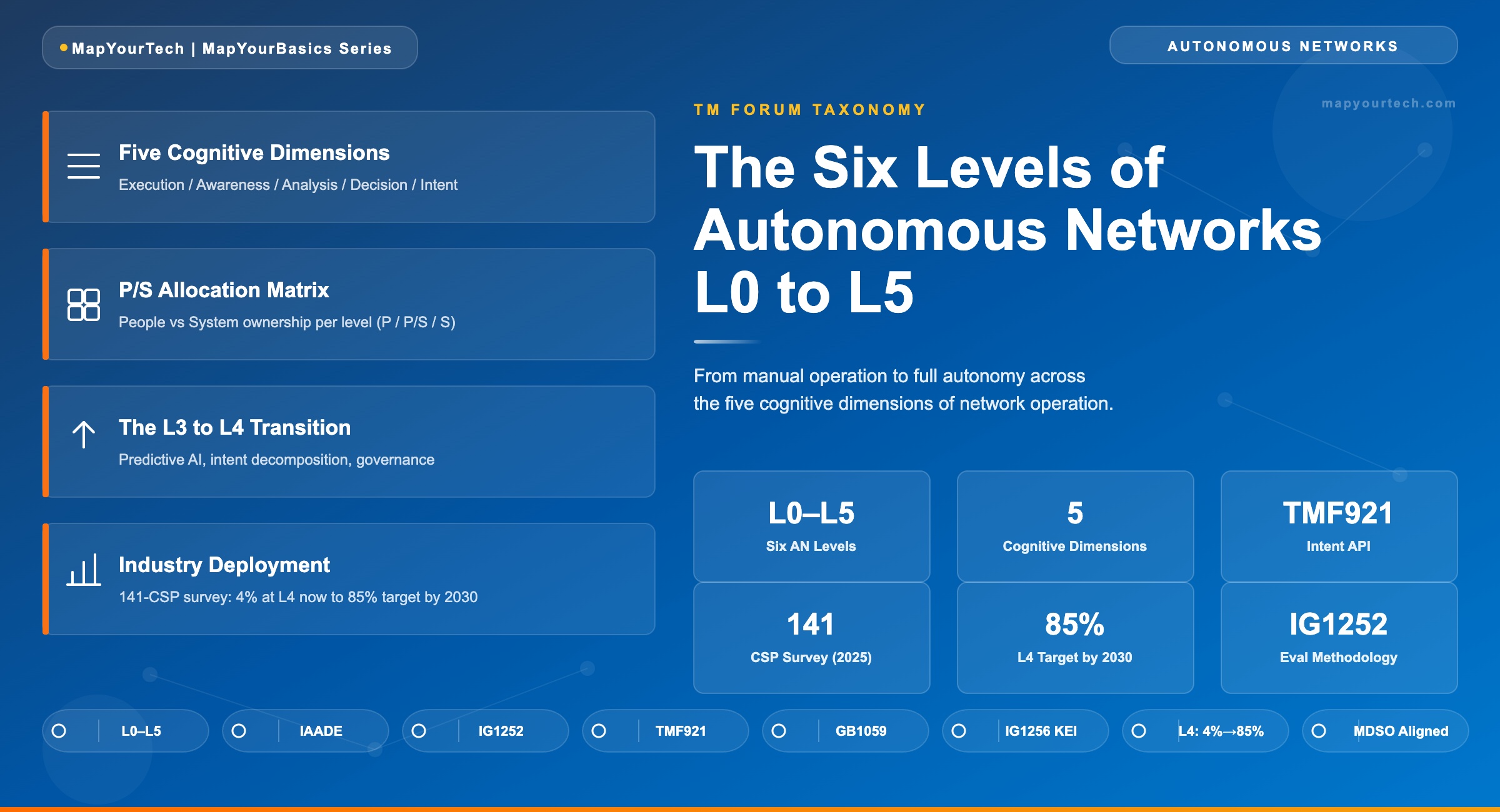
The Six Levels of Autonomous Networks: L0 to L5
A walk through the TM Forum taxonomy from manual operation to full autonomy — mapping each level across Execution, Awareness, Analysis, Decision, and Intent.
1. Introduction
Telecom operations have a staffing and complexity problem that pure automation cannot fix. A communications service provider (CSP) managing a converged radio, fixed, and optical transport network runs tens of thousands of configuration changes per day, monitors hundreds of millions of performance counters, and responds to fault events that cascade across layer and domain boundaries in under 60 seconds. Statically configured rule engines — the backbone of automation since the late 1990s — cannot keep pace with this volume when the failure pattern is novel, the service context is multi-domain, or the correct remediation depends on predicting what will happen over the next 72 hours rather than reacting to what happened in the last 30 seconds.
TM Forum's Autonomous Networks Project, formed in 2019, drew a formal line between automation and autonomy. Automation executes predefined rules. Autonomy involves intelligent systems making independent decisions about goals and methods. The six-level taxonomy the project produced — Autonomous Network Levels 0 through 5 (ANL 0–5) — gives CSPs a structured vocabulary and a measurable maturity model for charting the gap between where their operations sit today and where full cognitive self-management sits at the far end of the spectrum. The China Communications Standards Association (CCSA) has adopted the same taxonomy, and CSPs across five continents use it to define AN roadmaps and measure progress on specific operational scenarios.
This article dissects the taxonomy at engineering depth. Each level is characterized by which of the five cognitive dimensions — Execution, Awareness, Analysis, Decision, and Intent — the system handles autonomously versus which remain human-driven. The boundary between those two modes, and the architecture required to move that boundary, is the practical substance of the AN maturity model. For engineers building automation tooling, planning optical network automation programs, or evaluating whether a given deployment scenario qualifies as L3 or L4, this is the reference framework.
Scope of this article: The TM Forum AN Level taxonomy covers domain-agnostic network operations, including radio access, fixed access, core, IP, and optical transport. Examples and deployment data in this article reflect transport and optical operations contexts, consistent with this publication's audience. The underlying taxonomy applies identically across all network domains.
Manual Operation
All five cognitive dimensions handled entirely by human operators. System provides monitoring visibility only.
Assisted Operation
System executes specific repetitive subtasks based on pre-configuration. Execution begins to be system-shared.
Partial Autonomous
Closed-loop for specific units under static rules. Execution system-owned; Awareness and Analysis begin to shift.
Conditional Autonomous
Real-time environmental sensing enables policy-driven self-optimization within specific domains. Decision shifts partially to the system.
High Autonomous
AI modeling and continuous learning drive predictive closed-loop management. All dimensions except Intent are system-owned.
Full Autonomous
All five dimensions including Intent are system-owned. Cognitive self-adaptation across all domains, services, and lifecycle phases.
2. The Five Cognitive Dimensions
TM Forum's assessment methodology, published in Autonomous Network Levels Evaluation Methodology (IG1252), evaluates autonomy across five cognitive dimensions it terms IAADE: Intent/Experience, Awareness, Analysis, Decision, and Execution. Each dimension describes a distinct cognitive act in the network operations loop. The assignment of each act to either a human operator (P — People) or the automated system (S — System) defines which level a given operational scenario has reached. Partial sharing is designated P/S.
2.1 Execution
Execution is the lowest cognitive act: translating a determined action into operational commands on network devices — provisioning a circuit, applying a QoS policy, rerouting a lightpath, restarting a process. Execution is the first dimension to shift toward system ownership as automation matures, because it is the most mechanical and the most directly mapped to existing Network Management System (NMS) and SDN controller APIs. At L0, a technician types CLI commands or fills in a GUI form. At L2, the controller executes the action based on a predefined trigger rule, with no human interaction after the rule is configured. The physical mechanism through which a system takes execution responsibility is an API call from a controller to a network element — whether via TL1, NETCONF/YANG, RESTCONF, or gNMI. OpenConfig YANG models, described in detail in the OpenConfig configuration model guide, are the multi-vendor standard for this execution interface.
2.2 Awareness
Awareness is the network's ability to collect, correlate, and represent its own operational state accurately and in real time. This goes beyond raw telemetry collection — a system operating at L2 Awareness correlates multi-layer, multi-domain state into a coherent situational picture. At L0, awareness is a human operator reading dashboards and interpreting alarms manually. The shift toward system-owned awareness is enabled by streaming telemetry (gNMI, NETCONF), AI-based alarm clustering, and digital twin representations of network state. Awareness without the ability to act is still valuable — an accurate, real-time topology model with predictive OSNR projections gives a planning engineer a 60-second view that would take an expert analyst 20 minutes to reconstruct manually.
2.3 Analysis
Analysis is the diagnosis act: given what the system knows about current state (Awareness), what is wrong, what caused it, and what options are available? At L1 and L2, analysis is human-executed with system-generated reports as input. The shift to system-owned analysis — L3 and above — requires models that can reason about causality, not just correlation. A root cause analysis (RCA) engine that identifies a fiber bend as the common cause of 47 correlated optical alarms is performing system analysis. The failure condition that reveals an analysis gap is a novel failure mode for which no historical data exists: the system can detect that something is wrong (Awareness) but cannot determine what or why (Analysis fails). This boundary between L2 and L3 is where most production optical networks sit as of 2026.
2.4 Decision
Decision is the act of choosing among options produced by Analysis. At L3, the system proposes options; a human approves one. At L4, the system makes the decision without human approval, within defined intent boundaries. The practical difference between L3 and L4 Decision is accountability: at L3, a network engineer signs off on a rerouting decision. At L4, the controller decides to reroute, applies the change, monitors outcome, and closes the loop — the human sees the outcome in an audit log, not a change-approval workflow. The risk this creates is correlated failure from an incorrect AI decision applied at scale simultaneously; this is why TM Forum separates L4 Phase 1 (single-domain decisions) from L4 Phase 2 (cross-domain multi-agent decisions) in the implementation roadmap.
2.5 Intent / Experience
Intent is the highest cognitive dimension: the articulation of desired outcomes, business goals, or customer experience targets, expressed without specifying how to achieve them. Intents are the "what," not the "how." A business intent might be: "Maintain 99.999% availability for enterprise VPN service X at cost no greater than current baseline." The system must decompose that intent into service intents, resource intents, and specific actuation sequences — without the operator specifying any of those lower-level steps. At every level from L0 to L4, humans define the intent (the goal). At L5, the system generates its own intents. TM Forum's Intent Management API (TMF921) provides the standardized interface for communicating intents between autonomous domains.
Takeaway: The five cognitive dimensions are not a hierarchy of importance — they are a sequence in which autonomy arrives. Execution shifts first because it is the most structured. Intent shifts last because it requires the system to reason about business objectives. An operator can have system-owned Execution and Awareness while Decision remains entirely human — that combination maps to L2.
3. The P/S Allocation Matrix
The P/S allocation matrix is the formal definition of each AN level. P denotes a cognitive dimension handled by human personnel; S denotes system handling; P/S denotes shared responsibility, where both the human and the system contribute to the act. The matrix is published in TM Forum IG1252 and reproduced below. No level is defined by a single dimension — each level is the complete row, all five dimensions together.
| Level | Name | Execution | Awareness | Analysis | Decision | Intent / Experience |
|---|---|---|---|---|---|---|
| L0 | Manual Operation & Maintenance | P | P | P | P | P |
| L1 | Assisted Operation & Maintenance | P/S | P/S | P | P | P |
| L2 | Partial Autonomous Networks | S | P/S | P/S | P | P |
| L3 | Conditional Autonomous Networks | S | S | P/S | P/S | P |
| L4 | High Autonomous Networks | S | S | S | S | P/S |
| L5 | Full Autonomous Networks | S | S | S | S | S |
Reading the matrix horizontally shows what changes level to level. The transition from L2 to L3 shifts Awareness from P/S to S and introduces P/S in Decision — meaning the system takes full ownership of sensing and state-building, and begins to participate in the choice of action. The transition from L3 to L4 is the most consequential shift in the entire taxonomy: Analysis moves from P/S to S, Decision moves from P/S to S, and Intent moves from P to P/S. The system now analyzes problems without human interpretation and executes solutions without human approval. Humans retain the goal-setting function (Intent) but lose explicit oversight of every individual operational decision.
An important boundary condition: The P/S matrix describes an operational scenario, not an entire network. A CSP may be at L3 for fault management in the optical transport domain and simultaneously at L1 for cross-domain service activation. AN level assessment targets a specific evaluation object — a named operational use case in a specific technology domain — not the network as a whole.
4. L0 — Manual Operation and Maintenance
At L0, every cognitive act from intent-setting through execution is performed by human operators. The network management system delivers alarms and performance counters to a dashboard; what the operator does with that information is entirely unaided. Circuit provisioning requires a technician to log into an NMS, navigate to the correct slot, enter parameters, and commit the change. Fault isolation requires a NOC engineer to correlate alarms across systems, check OTDR traces, query performance history from multiple screens, and make a judgment call about the root cause. Configuration changes generate change-request tickets that route through an approval chain lasting hours or days.
L0 is not a failure state — it is the operational baseline from which every network starts. In small networks or in specialized operations contexts (high-security government networks, submarine cable wet plant operations under maintenance), L0 oversight for certain tasks is a deliberate design choice, not a capability gap. The distinction between L0 and L1 is not the presence of any tooling — L0 environments typically have NMS platforms, alarm management systems, and performance monitoring dashboards — but whether those tools assist the human in executing specific repetitive tasks automatically. If every action still requires a human to initiate it, the operation is L0 regardless of how sophisticated the monitoring platform is.
An optical NOC engineer receives an LOS alarm on a 400G channel at 02:47. The engineer opens the DWDM NMS, navigates to the affected channel, checks the received optical power, opens the OTDR trace viewer for the span, identifies a power drop of 4.2 dB at km 67, cross-checks the span database for splicing records, concludes a fiber break, and opens a ticket to dispatch a field crew. Every step in that sequence — from identifying the alarm to deciding to dispatch — was initiated and executed by the engineer. That is L0 Analysis and Decision.
5. L1 — Assisted Operation and Maintenance
L1 introduces system assistance for specific, repetitive subtasks that previously required full human attention. The system can execute pre-configured sequences, record operational actions in a traceable log, and provide structured guidance during manual operations. Critically, L1 does not close the loop — a human still must initiate each operational cycle, approve any configuration change, and validate any analytical output. The system is a power tool in the engineer's hands, not an autonomous agent.
The practical artifacts of L1 automation include: script-driven configuration templates that a technician invokes by name, alarm filtering rules that suppress known-benign alarms and surface only action-worthy events, and workflow engines that track change-request state automatically. Zero-touch provisioning for repeatable circuit types (adding a wavelength to an existing ROADM mesh where path computation is predefined) sits at the L1/L2 boundary — the system handles execution mechanics, but a human initiates each provisioning run. Streaming telemetry collection via gNMI from DWDM and OTN nodes, as described in the prompt engineering and network automation guide, enables the higher-resolution Awareness that L1 requires without full system-owned interpretation.
5.1 Where L1 Breaks
L1 tooling breaks when the subtask leaves the pre-configured boundary. A zero-touch provisioning system configured for 100G channels on a specific route fails when a new traffic demand arrives on a path the template was not designed for. A script that restores a primary LSP after a failure takes the correct action 95% of the time; the 5% of cases where secondary constraints are present (fiber diversity conflict, capacity exhaustion on the restore path) require a human who can reason about the full network context. The failure mode of L1 is not system error — it is scope boundary: the system handles what it was configured to handle and produces exceptions or does nothing for everything else.
Takeaway: L1 systems are fully deterministic — their behavior is exactly as configured, no more. The operational value is reduction of engineer time on repetitive, well-understood tasks. The engineering risk is false confidence: an L1 system that handles 80% of provisioning requests autonomously can mask the skill degradation in the 20% of cases that genuinely require expert judgment.
6. L2 — Partial Autonomous Networks
L2 crosses the first structural threshold: Execution becomes fully system-owned. The system no longer waits for a human to trigger an action — it monitors defined conditions, and when those conditions are met, it acts. The closed loop is active within a bounded scope and under statically configured rules. An L2 optical controller automatically reroutes a wavelength when an OSNR threshold falls below a configured floor, adjusts EDFA gain targets when span conditions change, or triggers a pre-computed protection switch when a line failure is detected — all without waiting for engineer approval. The key qualifier is "under statically configured rules": the system's response space is fully predetermined at deployment time.
Awareness at L2 is P/S: the system collects and aggregates telemetry from across the domain, but a human engineer still makes final sense of abnormal patterns, reviews trend reports, and decides which anomalies warrant investigation. Analysis is also P/S: the system may produce suggested root-cause hypotheses from a rule-based correlation engine, but the engineer validates and acts on those suggestions rather than the system acting on its own analytical output.
6.1 Static Rules as the L2 Ceiling
Static rules define both L2's capability and its upper boundary. A rule that says "if OSNR on channel X falls below 18 dB, switch to pre-computed protection path Y" handles the specific failure scenario it was written for. It fails when: the protection path is also degraded, the threshold is wrong for the actual modulation format in use, the degradation is gradual (requiring trend analysis, not threshold comparison), or a new network topology element was added that invalidates the pre-computed path. These boundary conditions represent the transition from L2 to L3 — the system needs to sense the actual current environment, not just compare against a static threshold.
Most optical network operators who have deployed an SDN controller with automatic protection switching are operating at L2 for fault management. As of 2026, according to TM Forum's regional survey of 141 CSP respondents, 31% of operators reported L2 as their current AN level for their most mature operational domain — the largest single cohort in the survey population.
An optical controller monitors per-channel Q-factor on a 48-channel DWDM system. For each channel, a configured rule sets a Q-factor floor 1 dB above the FEC correction threshold for the deployed modulation format. When channel 32 (193.1 THz, 200G DP-16QAM) reports Q-factor below 11.5 dB for three consecutive 15-minute intervals, the controller executes a pre-computed path switch to an alternate route with 2.3 dB additional margin. The engineer sees an audit entry; no approval was required. This is L2: the decision criteria and action were defined at commissioning time. The system cannot reason about why the degradation occurred, cannot evaluate whether the alternate route will remain viable tomorrow, and cannot adapt the threshold if the modulation format changes.
7. L3 — Conditional Autonomous Networks
L3 shifts Awareness to full system ownership and introduces system participation in both Analysis and Decision. The defining capability TM Forum describes is that the system "senses real-time environmental changes and in certain network domains will optimize and adjust itself to the external environment to enable closed-loop management via dynamically programmable policies." Dynamically programmable policies is the key phrase: the response rules are no longer static. The system updates its own policy parameters based on what it observes about current conditions.
Full system-owned Awareness at L3 means the network management stack can ingest, correlate, and interpret telemetry across the relevant domain without a human analyst reviewing each data stream. AI-based alarm correlation, OSNR anomaly detection, and predictive fault management running in production optical NOC environments represent the Awareness-to-system shift that L3 requires. Published field evidence from 2024 and 2025 shows that ML-based alarm clustering reduces the alarm storm generated by a fiber cut from several hundred actionable alarms to a single root-cause alert, with recall rates above 90% in production deployments — a direct enabler of system-owned Awareness.
7.1 Policy-Driven Closed Loop
The L3 closed loop uses policies that the system adjusts based on runtime analysis, rather than thresholds fixed at deployment. A traffic engineering policy that redistributes load across parallel paths when aggregate utilization exceeds 70% — and adjusts the trigger threshold based on time-of-day traffic patterns the system has learned — is an L3 construct. The operator writes the policy objective ("maintain link utilization below X% with margin Y"); the system determines the specific thresholds and re-optimization frequency based on what the network is actually doing. Decision remains P/S: the system presents the proposed optimization, provides its analytical rationale, and the operator approves or overrides before the change is committed. For well-understood high-frequency events (re-optimizing ROADM power levels every 60 seconds based on real-time optical power measurements), the approval gate may be replaced by a defined override window — the system acts unless overridden within N seconds.
7.2 Where L3 Is Today
TM Forum's survey data from 2025 shows 17% of CSPs had achieved L3 for at least one operational domain. The 2026 target shows 46% of CSPs aiming for L3 — representing the industry's near-term center of gravity. Optical transport fault management and performance optimization are the domains with the highest L3 maturity, driven by the tractability of optical impairment physics and the availability of per-channel telemetry at 15-second granularity from coherent DSP-equipped transponders. For engineers pursuing practical AI deployment in the NOC, the practical AI adoption guide for NOC engineers describes where production deployments stand and where the boundary conditions are.
Takeaway: L3 is the first level where the network actively adapts to environmental changes rather than reacting against a static threshold. The gap between L2 and L3 is not one of technology availability — every major optical controller platform has the API surface required — but one of model training data quality, telemetry coverage, and organizational trust in AI-generated decisions with human confirmation gates.
8. L4 — High Autonomous Networks
L4 is the level at which Awareness, Analysis, Decision, and Execution are all system-owned — every cognitive dimension except Intent. The human operator retains shared ownership of Intent — the definition of goals — but relinquishes explicit approval authority over individual operational decisions. The new transitions at L4 are Analysis and Decision moving from P/S to S; Awareness became system-owned at L3 and Execution at L2. The system uses predictive AI modeling and continuous learning to manage service delivery and customer experience across a network domain, closing loops that span fault management, performance optimization, and capacity engineering without per-action human sign-off.
TM Forum's published AN blueprint describes two phases of L4 implementation with different timeline horizons. Phase 1, targeted for 2025–2027, focuses on autonomous closed-loop within a single domain managed by an AI agent. Phase 2, targeted for 2028–2030, extends to end-to-end closed-loop management across complex cross-domain scenarios using multi-agent collaboration. The distinction matters architecturally: Phase 1 L4 is a harder problem than L3 but is a bounded one; Phase 2 L4 introduces inter-agent coordination challenges across domain ownership boundaries that no single organization controls.
8.1 What L4 Requires Technically
Achieving L4 for a given operational scenario requires three technical components operating together. First, a predictive AI model that can forecast network state accurately enough to act on predictions — not just react to present-state thresholds. Second, a decision engine that can select among competing options without human approval, within defined intent constraints, and produce an audit trail that satisfies regulatory and operational review requirements. Third, a continuous learning loop that updates model parameters as network behavior changes — either through scheduled retraining or online learning mechanisms. A field trial published in 2024 by researchers from a major optical equipment vendor demonstrated an LLM-powered AI agent managing a 440-km testbed loop with six OAs via NETCONF/YANG over an SDN controller; the agent handled wavelength add/drop sequences, adjusted launch powers, and resolved OSNR margin violations without per-action operator intervention. That is L4 Execution, Analysis, and Decision operating within a defined scenario boundary.
8.2 Intent at L4: P/S in Practice
At L4, Intent is P/S: the operator defines the goal (business intent), and the system interprets that intent into resource-level actions without operator-specified implementation steps. TM Forum's Intent Management API (TMF921) is the standardized mechanism for expressing intent to an autonomous domain. A business intent expressed as "ensure 10G enterprise VPN service meets 99.99% monthly availability at current contracted cost" passes through a service intent manager, which decomposes it into resource intents for each domain: the optical transport domain receives a resource intent specifying the OSNR margin floor, restoration time objective, and path diversity requirement. The optical L4 system translates those resource intents into specific actions across the DWDM layer — without the operator specifying which channels, which paths, or which protection sequences to use.
The L4 boundary condition that prevents full Intent autonomy — the reason Intent stays at P/S rather than S — is value conflict. An L4 system optimizing for availability may choose to deploy redundant capacity in a way that increases cost. An L4 system optimizing for cost may trade availability margin against budget. Humans must retain the authority to define how those competing objectives are weighted. At L5, the system generates its own intents and resolves those value conflicts autonomously.
An optical L4 controller monitors 96 DWDM channels on a 2,400-km core backbone. At 14:22, the predictive model identifies a 73% probability that span 8 of segment B will experience an OSNR degradation event within the next 6 hours, based on temperature-correlated Raman noise floor trends from the prior 48 hours of telemetry. The decision engine selects preemptive rerouting of the 12 highest-capacity channels over alternate path C, which provides 2.8 dB additional OSNR margin without service interruption. The controller verifies available capacity on path C via the inventory model, applies the reroute via NETCONF transactions to the source and destination ROADMs, monitors channel OSNR through the transition, and closes the maintenance ticket when all 12 channels confirm margin above threshold. The operator sees a predictive action report in their morning summary — no approval was required or requested.
8.3 High-Value L4 Scenarios
TM Forum's Autonomous Network Innovation Pioneer Project, launched in September 2024, identified 20 high-value scenarios for L4 implementation. In the optical transport domain, the highest-priority scenarios include: end-to-end service assurance and complaint handling for private line services, fault management across optical specialties (DWDM, OTN, dark fiber), and network change management for IP and transport network re-optimization. These scenarios were selected because they combine high operational frequency (daily or weekly cycles), high impact when handled slowly (customer SLA impact), and tractable AI model inputs (structured telemetry, defined topology state).
9. L5 — Full Autonomous Networks
L5 is the theoretical end state: every cognitive dimension including Intent is system-owned. The system has closed-loop automation capabilities across multiple services, multiple domains — including partners' domains — and the entire service lifecycle via cognitive self-adaptation. Critically, the system generates its own intents. At L5, the network can decide not only how to deliver a service, but what service objectives to pursue, how to balance competing business goals, and whether to prioritize customer experience against carbon footprint when the two conflict.
TM Forum acknowledges explicitly that L5 may not be a universal production target. Some operators may stop short of implementing L5 because they are not willing to exclude humans completely from service delivery and assurance processes. The regulatory, liability, and operational risk questions raised by a network that autonomously modifies its own goals are not merely technical. An L5 system that decides to reduce power consumption by degrading quality of experience for lower-priority services — without any human having defined that as an acceptable trade-off — is operating in a governance space that most CSP frameworks do not yet address.
9.1 L5 as a Design Reference, Not an Operational Target
The practical value of L5 in the taxonomy is as a reference point that defines the direction of travel, not as a near-term deployment specification. Every L4 decision about intent representation, value-weighting mechanisms, and multi-domain governance is a step toward or away from L5 feasibility. Organizations that design their L4 intent frameworks with machine-interpretable value hierarchies — rather than hard-coded priority rules — are building toward L5-compatible architectures even if they never deploy L5 in production. The technical requirement unique to L5 is a system that can generate, evaluate, and revise its own operational goals without any predefined goal taxonomy authored by a human designer.
10. Assessment Methodology
TM Forum publishes the formal assessment procedure in Autonomous Network Levels Evaluation Methodology (IG1252), with a supporting evaluation tool codified in GB1059. The procedure evaluates AN levels for specific operational scenarios rather than for an entire network or organization. This is an important design choice: it allows a CSP to have a rigorous claim of "L3 for optical fault management in the metro domain" without implying anything about their RAN or core network maturity.
10.1 Evaluation Objects
The first step in any AN level assessment is defining the evaluation object: the operational use case, the network technology domain it covers, and the operational flow being assessed. For a metro optical domain, an evaluation object might be "automated wavelength restoration following fiber cut, single-domain DWDM, reactive closed-loop." For a fixed access domain, it might be "proactive customer fault identification before customer-reported SLA breach, multi-service access domain, predictive closed-loop." The specificity of the evaluation object determines how meaningful the resulting AN level claim is. A vague evaluation object produces a score that is difficult to reproduce or benchmark.
10.2 The IAADE Scoring Approach
The assessment questionnaire evaluates each of the five cognitive dimensions — Intent, Awareness, Analysis, Decision, and Execution — for the defined evaluation object. Each dimension contains a set of tasks, and each task is scored against defined criteria. The aggregate score across all five dimensions maps to a level. At L3 and below, the assessment focuses on policy-driven operations using existing management interfaces. At L4, the assessment requires evidence that AI models generate rules enabling the network to optimize itself — not simply that AI tools are deployed, but that those tools are operating in the closed-loop path without per-action human approval.
10.3 Key Effectiveness Indicators
TM Forum pairs AN level assessment with a Key Effectiveness Indicator (KEI) framework published in IG1256. KEIs measure the business value of autonomous operations rather than just the technical maturity. A KEI for fault management might be mean time to repair (MTTR) for customer-affecting events. A KEI for performance optimization might be the percentage of channels operating within 0.5 dB of optimal OSNR margin. The KEI framework allows CSPs to calibrate whether advancing from L2 to L3 actually reduces MTTR by a measurable factor — which is the business case that justifies the architectural investment.
11. Architecture Requirements by Level
Each AN level transition imposes specific architectural additions. The table below maps level transitions to the primary architectural requirement that enables them. This is not a procurement checklist — it is an engineering boundary identification: what capability the system must possess that it did not have at the prior level.
| Transition | Primary New Capability | Enabling Technology | What Fails Without It |
|---|---|---|---|
| L0 → L1 | Script-driven task execution with traceability | NMS workflow engine, NETCONF/YANG templating | Every task requires manual CLI or GUI initiation; no audit trail beyond change tickets |
| L1 → L2 | Condition-triggered autonomous execution within static rules | SDN controller with event-driven rule engine; streaming telemetry | System cannot close the loop — every execution step still waits for human trigger |
| L2 → L3 | Dynamic policy adaptation based on real-time environmental sensing | ML-based analysis models; digital twin; AI operations layer | System responds to present-state thresholds only; cannot adapt to evolving conditions or novel patterns |
| L3 → L4 | Autonomous decision-making without per-action human approval; predictive closed loop | AI agents; intent management (TMF921); continuous model retraining | Every non-trivial decision still requires human confirmation; system cannot act on predictions |
| L4 → L5 | System-generated intents; autonomous value-conflict resolution | Machine-interpretable value hierarchies; multi-agent goal negotiation | All goal-setting remains human-authored; system cannot autonomously reprioritize objectives |
11.1 The Autonomous Domain Architecture
TM Forum's AN target architecture organizes the network into autonomous domains (ADs). Each AD operates independently, guided by the operator's business objectives, while hiding implementation details from other ADs and from customers through an API abstraction layer. Within an AD, three operational layers operate concurrently: Business Operations (highest, intent-receiving layer), Service Operations (service lifecycle management), and Resource Operations (network element control). Closed loops operate at each layer — a resource-layer closed loop handles OSNR optimization minute-to-minute; a service-layer closed loop manages SLA assurance hour-to-hour; a business-layer closed loop optimizes capacity investment over weeks to months. Intent flows downward through the layers (business intent decomposes into service intent, which decomposes into resource intent). Reports and status flow upward.
When multiple ADs are deployed — optical transport as one AD, mobile RAN as another, fixed access as a third — the upper-layer service operations use TMF921 intent interactions between ADs to manage end-to-end service lifecycle. This cross-domain intent architecture is the foundation for L4 Phase 2 and L5. For optical transport engineers, the immediate implication is that an optical AD must expose intent interfaces (implementing TMF921) alongside its existing device-management APIs, and must be capable of accepting resource intents from a service orchestration layer without those intents specifying the optical implementation path. As explored in the ITU-T standards and future technologies overview, 400-Gbps era optical backbones provide the transport foundation for this architecture.
12. Industry Deployment Status
TM Forum's 2025 regional survey of 141 CSP respondents across Africa, the Middle East, Asia-Pacific, Europe, North America, and CALA provides the most comprehensive published snapshot of where the industry sits on the AN level scale. As of the survey baseline, 12% of respondents placed their organization at L0, 36% at L1, 31% at L2, 17% at L3, and 4% at L4 for their most mature operational domain. No respondent claimed L5.
The forward trajectory is steep. By the 2026 horizon, 85% of respondents planned to be at L3 or above, with 23% targeting L4. By 2030, 85% targeted L4 — a figure consistent with the industry pledges TM Forum collected from more than a dozen CSPs to achieve Level 4 autonomy in multiple domains between 2025 and 2027. The geographic distribution shows operators in Africa and the Middle East are more likely to pursue ambitious implementation strategies, driven by network scaling challenges and quality-led service competition. North American and CALA operators showed more conservative near-term roadmaps, with stronger alignment to L2/L3 consolidation before L4 pursuit.
12.1 Why L4 Is the Current Inflection Point
Four percent of operators at L4 as of 2025, with 85% targeting L4 by 2030, defines a six-year window during which the industry must cross a substantial architectural gap. L4 is not a natural extension of L3 — it requires the organization to accept that AI systems will make operational decisions without per-action human approval. That acceptance depends not only on the quality of the AI models, but on the audit frameworks, liability policies, and regulatory environments in which those decisions operate. CSPs that are building L4 foundations now are investing simultaneously in model accuracy, explainability tooling, and operational governance frameworks that define which decisions can be delegated and which retain mandatory human confirmation gates even at L4.
Industry context: AN Level assessment is per-scenario, so a CSP claiming "L4 progress" typically means one or several high-value operational scenarios have been demonstrated at L4 in production, not that the entire network operates at L4. The industry's 2030 target of 85% at L4 should be read as: 85% of CSPs will have implemented at least one production L4 scenario in at least one domain. Full-network L4 across all technology domains and operational flows is a multi-decade trajectory.
13. The L3-to-L4 Transition — The Critical Engineering Step
Every other level transition in the AN taxonomy has a reasonably clear engineering path. L0 to L1 requires workflow tooling and scripting. L1 to L2 requires a controller with an event-driven rule engine and API connectivity to the network layer. L2 to L3 requires AI model deployment and telemetry infrastructure expansion. The L3-to-L4 transition is uniquely difficult because it requires changing not just the technical architecture but the operational trust model: the organization must accept that the system will make decisions of operational consequence without human review of each individual action.
13.1 Technical Prerequisites
Three technical prerequisites must hold simultaneously before L4 is achievable for a given scenario. The AI model must have demonstrated predictive accuracy sufficient to justify autonomous action — for optical fault management, this typically means OSNR degradation prediction error below 0.5 dB at 6-hour horizon for the specific fiber plant and transponder mix being managed. The decision engine must produce decisions that are both correct and explainable — an L4 controller that makes the right rerouting decision but cannot produce a machine-readable justification trail will fail operational review processes. The continuous learning loop must remain bounded — model drift under novel traffic patterns or network changes cannot be allowed to silently degrade decision quality below the threshold that justified autonomous operation.
13.2 Organizational Prerequisites
The organizational gap between L3 and L4 is at least as significant as the technical gap. At L3, engineers stay in the decision loop and can override any system recommendation. Moving to L4 means the engineering team transitions from decision-makers to intent-setters and exception handlers. That transition requires: defined intent expression standards (so engineers can specify what they want from the system in the domain language of the AN level framework), override procedures for the cases where a human must intervene in an autonomous action, and audit review processes that provide engineering accountability without requiring per-decision approval. The zero-impact software upgrade methodology offers a practical template for progressive automation trust-building that transfers directly to L4 operational governance design.
13.3 The Role of AI Agents
TM Forum's L4 Phase 1 blueprint (2025–2027) positions AI agents — autonomous software entities that can plan, execute, and evaluate actions toward a goal — as the primary technical mechanism for achieving single-domain L4. An AI agent for optical fault management receives a resource intent ("maintain OSNR margin above 3 dB for all active channels in domain X"), continuously monitors the relevant telemetry, predicts degradation events, selects and executes corrective actions from a defined capability space, and evaluates outcomes against the intent. The agent architecture maps directly to the P/S transition at L4: the agent owns Analysis, Decision, and Execution; the operator who defined the resource intent owns Intent (P/S because the operator sets the intent but the system may refine it within defined bounds).
Multi-agent systems for L4 Phase 2 introduce coordination challenges absent in single-agent L4. When an optical transport agent and a mobile RAN agent are both responding to a shared backhaul capacity constraint, the decisions of each affect the feasibility of the other's optimization. TM Forum's multi-domain intent architecture addresses this through hierarchical intent decomposition — a service intent manager decomposes the top-level service objective into resource intents for each domain agent, and the service intent manager arbitrates when domain agents report conflicting capacity requirements. The evolving role of optical engineers in this agent-mediated architecture is to own the intent specification layer and the exception boundary definitions, not the per-action execution decisions.
13.4 Standards Alignment
TM Forum coordinates the AN Level taxonomy with other standards bodies through the Multi-SDO (MDSO) collaboration that includes 3GPP, CCSA, ETSI, GSMA, IEEE, IETF, ITU, and NGMN. 3GPP defines autonomous network architecture for 5G and 5G-Advanced radio access networks. IETF defines intent-based networking protocols relevant to the IP and routing layers. ITU-T Study Group 15 addresses the optical transport domain specifically. The convergence of these standards toward a common taxonomy means that an L4 optical transport domain built on TM Forum's architecture and TMF921 intent APIs can interoperate with an L4 mobile core built on 3GPP's corresponding framework — which is the precondition for true end-to-end autonomous service management.
Takeaway: The L3-to-L4 transition is the most consequential step in the AN maturity journey. It requires simultaneous investment in AI model accuracy, intent expression infrastructure (TMF921), operational governance frameworks for AI-autonomous decisions, and organizational capability to shift from decision-making to intent-setting roles. CSPs that treat it as a technology upgrade rather than an operational transformation will stall at L3.
References
- TM Forum, Autonomous Networks Level 4 Industry Blueprint — Getting to Level 4, Annual AN Journey Guide.
- TM Forum, Autonomous Network Levels Evaluation Methodology (IG1252), Autonomous Networks Project.
- TM Forum, Autonomous Networks Business Requirements and Framework (IG1218).
- TM Forum, Intent in Autonomous Networks (IG1253).
- TM Forum, Autonomous Networks Effectiveness Indicators KEI Framework (IG1256).
- TM Forum, Intent Management API (TMF921), Open API Program.
- TM Forum, Autonomous Network Levels Evaluation Tool (GB1059).
- TM Forum, A Regional Guide to Autonomous Networks Progress, Survey of 141 CSP Respondents.
- TM Forum, Metrics Framework (GB935) and Metric Definitions (GB988).
- Sanjay Yadav, "Optical Network Communications: An Engineer's Perspective" — Bridge the Gap Between Theory and Practice in Optical Networking.

Optical Communications & Network Automation Expert | Author of 3 Books for Optical Engineers | Founder, MapYourTech
Optical networking engineer with nearly two decades of experience across DWDM, OTN, coherent optics, submarine systems, and cloud infrastructure. Founder of MapYourTech. Read full bio →
Follow on LinkedIn