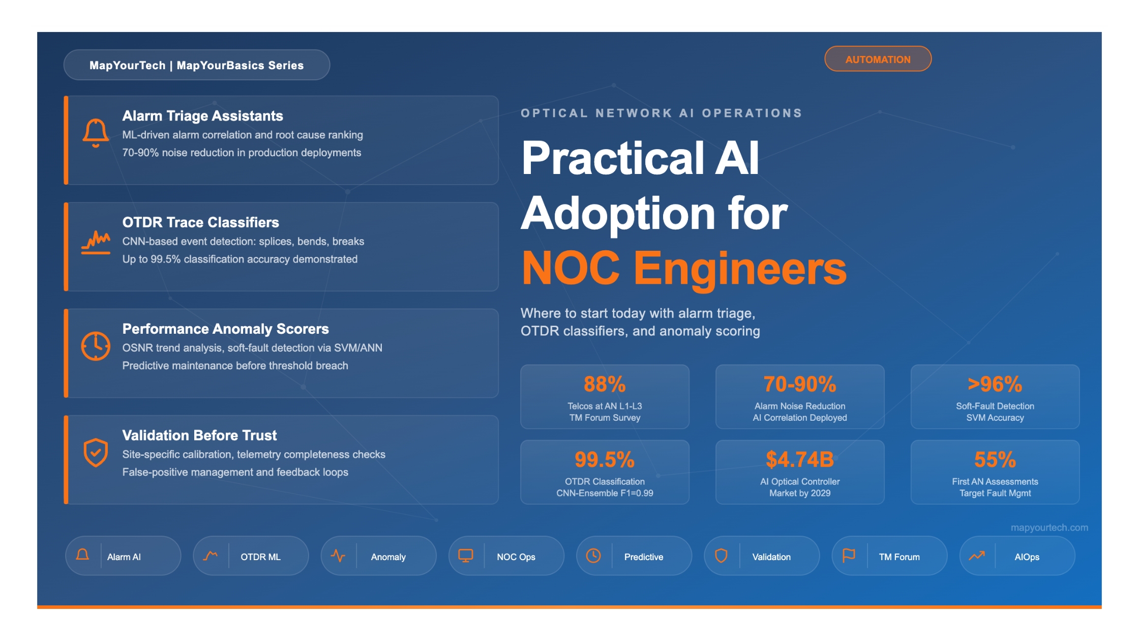

Practical AI Adoption for NOC Engineers: Where to Start Today
Actionable starting points for NOC teams evaluating AI tools — alarm triage assistants, OTDR trace classifiers, and performance anomaly scorers — with guidance on what to validate before trusting outputs in an operational context.
Estimated reading time: 15 minutes
At a Glance
- AI in the optical NOC is production-ready for three specific categories: alarm correlation, OTDR trace analysis, and optical performance anomaly detection.
- Most operators are at TM Forum Autonomous Networks Level 2–3; fault management is the highest-priority automation target across every region.
- AI does not replace NOC engineers — it reallocates work from reactive alarm watching to higher-value tasks such as model oversight and complex incident management.
- Every AI tool deployed in an operational NOC must be validated on your own network's telemetry, not just vendor benchmarks.
- Start with alarm triage, where data volumes are highest and return on effort is fastest to demonstrate.
1. Introduction
Optical network operations centres (NOCs) have spent decades refining the art of watching dashboards, triaging alarm floods after fiber cuts, and manually correlating performance telemetry from hundreds of DWDM channels. That approach worked when networks carried tens of wavelengths per fiber. It does not scale when a single fiber cut on an 80-channel DWDM system generates upward of 1,500 correlated alarms across the optical transport network (OTN) hierarchy in under a minute.
Artificial Intelligence (AI) and Machine Learning (ML) tools designed for NOC operations have moved from research prototypes to production deployments. As of 2026, according to NVIDIA's annual "State of AI in Telecommunications" survey, 89% of telecom respondents plan to increase their AI budgets in the next twelve months, with network automation overtaking customer experience as the top AI investment priority. The AI optical network controller market is projected to reach approximately $4.74 billion by 2029, reflecting compound annual growth of around 20%.
Yet most NOC engineers, the people who actually receive the alarms and make the decisions, have limited guidance on where to begin. This article addresses that gap. It identifies three specific, production-ready AI application categories for optical NOC teams: alarm triage assistants, Optical Time-Domain Reflectometer (OTDR) trace classifiers, and performance anomaly scorers. For each, it explains what the tool does, what data it needs, what accuracy to expect, and what to check before trusting its outputs in a live operational environment.
2. How It Works: The AI-Assisted NOC Architecture
An AI-assisted optical NOC does not replace the existing Network Management System (NMS) or the operations workflow. Instead, it adds an intelligence layer between the raw telemetry sources and the engineer's decision point. The general data flow follows a three-stage pipeline: ingest and normalize, apply AI models, and present actionable results with confidence indicators.
The data sources feeding this pipeline vary by operator, but the most common are: NMS alarm streams (via SNMP, TL1, or NETCONF notifications), OTDR test results from embedded or remote test units, coherent Digital Signal Processor (DSP) telemetry from transponders and pluggable optics, and Configuration Management Database (CMDB) records for topology context. The Common Management Interface Specification (CMIS), standardized through the OIF, provides consistent hooks into DSP diagnostics across 400G+ pluggable modules, making telemetry collection increasingly uniform. Versatile Diagnostics Monitoring (VDM) observables such as pre-FEC Bit Error Rate (BER) and Signal-to-Noise Ratio (SNR) are now available from these modules and are directly applicable as AI model inputs.
An optional but increasingly common addition is a Large Language Model (LLM) layer connected via retrieval-augmented generation (RAG) to standard operating procedures, vendor documentation, and historical ticket databases. This allows NOC engineers to query alarm context and recommended actions in natural language rather than navigating multiple documentation sources manually.
3. Alarm Triage Assistants
3.1 The Problem They Solve
A single fibre cut on an 80-channel DWDM system can generate upward of 1,500 alarms in under 60 seconds, cascading across Loss of Signal (LOS), Loss of Frame (LOF), Alarm Indication Signal (AIS), Remote Defect Indication (RDI), and client-side alarms at every point in the OTN hierarchy. Traditional threshold-based alarm management systems present all of these to the operator simultaneously. The result is alarm noise that obscures the one or two root-cause events an engineer actually needs to act on.
AI-based alarm triage assistants apply ML-driven correlation to cluster related alarms, suppress transient events, rank probable root causes by likelihood and service impact, and present a clean, prioritised view. Production deployments have demonstrated 70–90% alarm noise reduction using these techniques, meaning the engineer sees tens of actionable incidents rather than thousands of raw alarms.
3.2 How They Work
Alarm triage engines typically combine several ML approaches. Unsupervised clustering algorithms group alarms that arrive within a time-correlated window and share topological relationships (same fibre span, same ROADM degree, same OTN trail). Supervised classifiers, trained on historical incident records, assign a root-cause probability to each cluster. More advanced implementations add service-impact scoring by cross-referencing alarm clusters against CMDB records and SLA definitions, so the engineer knows not just what happened, but which customers are affected and how severely.
Modern agentic AI frameworks go further. Multi-agent architectures now assign specialised agents to different tasks: one for alarm correlation and root cause analysis, another for querying network devices in real time, and a third for retrieving relevant knowledge from runbooks and past incidents. These agents coordinate through an orchestrator that manages task delegation and shared context. As of early 2026, operators such as Far EasTone Telecom report that nearly 60% of NOC operations are AI-assisted, with approximately 10,500 operational tasks executed per month including incident summaries, automated ticket closure, and proactive notifications.
Practical Example: Alarm Storm After a Fibre Cut
A long-haul network experiences a fibre break between two amplifier sites. The NMS floods the NOC with 1,200+ alarms in 30 seconds: LOS on every DWDM channel, LOF and AIS propagating through OTN, client-side CSF alarms on protected services, and secondary OSNR degradation warnings on adjacent spans due to power transients. The AI triage engine clusters all of these into a single incident, identifies the fibre break location (correlated with OTDR data), maps the affected services, and presents the engineer with one ranked root cause and an SLA impact summary — all within seconds of the event.
3.3 What to Expect
Well-calibrated alarm triage systems reduce Mean Time to Identify (MTTI) from tens of minutes (manual correlation) to seconds. Documented case studies report 20% ticket-volume reduction and 5-minute Service Level Objective (SLO) from alarm detection to ticket creation in managed NOC environments. For a Tier-1 telecom operator, AI-based alarm correlation reduced analyst investigation time by approximately 80% in the domains where it was deployed.
4. OTDR Trace Classifiers
4.1 The Problem They Solve
An OTDR sends a series of optical pulses into a fibre and measures the backscattered and reflected light as a function of time, producing a trace that maps the fibre's characteristics. Interpreting OTDR traces requires identifying events such as splices (downward slope changes), connectors (reflective peaks), bends (gradual attenuation increase), and breaks (sudden signal loss). In point-to-point links this is manageable. In dense access networks, fibre-to-the-home (FTTH) splits, or long-haul spans with dozens of splices and inline amplifiers, overlapping reflections, ghost events, and low signal-to-noise conditions make manual interpretation time-consuming, inconsistent, and error-prone.
4.2 How AI Classification Works
AI-powered OTDR classification applies deep learning models, primarily Convolutional Neural Networks (CNNs), to automatically detect and classify events on OTDR traces. The general approach treats the OTDR trace as a one-dimensional signal and applies object-detection techniques inspired by computer vision. A CNN extracts features from the backscatter waveform, identifies event locations, and classifies each as a splice, connector, bend, break, or other event type.
Research published in the Journal of Optical Communications and Networking demonstrated an ensemble classifier achieving 98% precision and 95% recall on measured OTDR traces, including successful mapping of events to specific optical distribution network branches. A hybrid CNN-ensemble framework combining CNNs with XGBoost, SVM, and Random Forest, validated on a dataset covering eight distinct fault categories, achieved 99.5% accuracy and an F1-score of 0.99. For practical rural deployments, an AI-augmented OTDR system using CNN classification improved detection accuracy from 71.2% (traditional thresholding) to 93.4% while reducing the false-positive rate from 18.9% to 7.1%.
Beyond static fault classification, AI-driven OTDR systems now perform trend analysis on repeated measurements. Gradual degradation, such as a 0.02 dB/month increase in splice loss, can be flagged as a predictive maintenance indicator long before it affects service. Some systems correlate OTDR data with environmental inputs (temperature, humidity) and alarm logs for cross-domain fault analysis.
Key capability: ML-based pattern recognition applied to state-of-polarization (SoP) rotation speed, monitored in digital coherent receivers, can predict fibre stress events such as bending and shaking before a break occurs. A naive Bayes classifier trained on Stokes parameter traces has demonstrated 95% accuracy in predicting various fibre stress events ahead of their actual occurrence.
4.3 Deployment Considerations
OTDR trace classifiers are trained on datasets that may not match your network. Fibre type, splice quality, connector models, environmental conditions, and test wavelength all affect trace characteristics. A model trained on G.652 fibre in a controlled environment may perform differently on aged G.655 fibre in a duct exposed to temperature cycling. Field performance testing on representative traces from your own plant is a non-negotiable step before deploying these classifiers in production. Public training datasets, such as those available on platforms like Kaggle, can supplement initial model training but cannot replace validation on site-specific data.
5. Performance Anomaly Scorers
5.1 The Problem They Solve
Optical performance metrics such as OSNR, pre-FEC BER, chromatic dispersion (CD), polarization mode dispersion (PMD), and amplifier gain fluctuate continuously. Traditional threshold-based monitoring fires an alarm only when a parameter crosses a static limit. This approach misses gradual degradation trends that indicate an impending failure, and it generates false alarms when parameters temporarily spike due to benign transients (traffic rerouting, protection switching, environmental temperature changes).
Performance anomaly scorers learn the normal baseline behaviour of each link and assign a continuous anomaly score that reflects how far current behaviour deviates from expectation, weighted by the rate of change and correlation across parameters. This enables detection of soft failures, the kind that do not trip hard thresholds but degrade margins over weeks or months.
5.2 How They Work
The most common approach uses an Artificial Neural Network (ANN) or Support Vector Machine (SVM) trained on historical telemetry to recognise normal operating patterns. When the trained model detects a pattern that deviates from the learned baseline, such as an unusual combination of adaptive filter weight changes in receiver DSP, it flags this as a potential soft failure. An SVM-based method proposed for optical link anomaly detection considered four specific soft failure types: laser linewidth increase, interchannel interference, ROADM Wavelength-Selective Switch (WSS) bandwidth reduction or centre frequency shift, and OSNR degradation from increased EDFA noise. This technique detected these failures with greater than 96% accuracy.
For predictive maintenance, time-series forecasting models such as Double Exponential Smoothing (DES) combined with SVM classifiers can predict equipment failures by continuously monitoring parameters including power consumption, laser bias current, laser temperature offset, and environment temperature. This approach has shown an average accuracy of 95% in predicting board-level failures before they occur.
Practical Example: EDFA Degradation Detection
A Tier-1 telecom operator monitors its long-haul optical links using AI-powered OSNR trend analysis. Over three weeks, the anomaly scorer detects a slow downward drift in OSNR on a specific span that has not yet crossed the alarm threshold. Correlation analysis identifies an ageing EDFA pump laser as the source. The system creates a predictive maintenance ticket, allowing technicians to schedule a proactive replacement before the amplifier fails and causes a service-affecting outage.
5.3 The Open Challenge: Data Availability
The single biggest obstacle to deploying ML-based anomaly detection in optical networks is the lack of extensive datasets corresponding to different faulty operational conditions. Network operators design for high reliability, which means genuine fault events are rare. Most operational data represents normal conditions, making it difficult to train classifiers that can distinguish between benign variations and genuine soft-failure signatures. Synthetic data generation, transfer learning from simulation environments, and federated learning across multiple operator datasets are active areas of development to address this gap.
6. What to Validate Before Trusting AI Outputs
Deploying an AI tool in a production NOC is not a software installation — it is an operational integration that requires validation on your own network's data. The following checklist applies to all three categories discussed in this article.
Validation Checklist for NOC AI Tools
1. Telemetry Completeness: Verify that you collect the data the model needs at the resolution it expects. AI is only as capable as the telemetry it receives. Assess three dimensions: sampling resolution (15-minute PM bins vs. real-time streaming), parameter completeness (does your NMS expose pre-FEC BER? SoP data? VDM metrics?), and history depth (most ML models need 3–6 months of baseline data to learn normal behaviour).
2. Site-Specific Calibration: Universal AI models that require no site-specific calibration are not achievable for physics-based optical predictions. Every deployed model must be validated against the target network's actual telemetry. OSNR prediction accuracy, for example, depends on knowing the exact amplifier configuration, fibre type, span losses, and channel loading of your specific network.
3. False Positive / False Negative Trade-off: For any classifier, ask the vendor to specify both precision and recall on a dataset representative of your network. A system with 99% accuracy but a 5% false-positive rate on a network generating 10,000 alarms per day produces 500 false alerts daily — enough to erode trust and lead operators to ignore AI recommendations entirely.
4. Explainability: Insist that the AI tool shows its reasoning, not just its conclusion. If it says a particular amplifier is the probable root cause, it should show which alarm correlations and which telemetry trends support that conclusion. This is needed both for engineer trust and for regulatory compliance in SLA-governed networks.
5. Feedback Mechanism: The model must be able to learn from engineer corrections. When the AI gets a root cause wrong and the engineer identifies the actual cause, that correction needs to flow back into the training pipeline. Without this feedback loop, model accuracy degrades as the network evolves.
7. Comparison: AI Use Cases at a Glance
| Criteria | Alarm Triage Assistants | OTDR Trace Classifiers | Performance Anomaly Scorers |
|---|---|---|---|
| Primary function | Cluster, suppress, and rank alarms by root cause and service impact | Detect, classify, and localise fibre events (splices, bends, breaks) | Score deviations from baseline optical performance metrics |
| Data inputs | NMS alarm stream, topology, SLA mappings | OTDR trace waveforms, fibre route maps | Coherent DSP telemetry: OSNR, pre-FEC BER, CD, PMD, SoP |
| ML approach | Unsupervised clustering + supervised classification | 1D-CNN, ensemble methods (SVM, XGBoost, RF) | ANN, SVM, time-series forecasting (DES) |
| Reported accuracy | 70–90% alarm noise reduction; 80% analyst time reduction | 93–99.5% classification accuracy (dataset-dependent) | >95–96% soft-fault detection accuracy |
| Maturity level | Production (multiple operator deployments) | Emerging production (point solutions, growing adoption) | Production for OSNR/BER; research for multi-parameter soft faults |
| Baseline data needed | 3–6 months of alarm and incident history | Labelled OTDR traces from the target fibre plant | 3–6 months of continuous DSP telemetry per link |
| Recommended start | Begin here — highest volume, fastest ROI demonstration | Second priority — start with long-haul spans where OTDR is routine | Third priority — requires well-established telemetry collection first |
8. Standards, Ecosystem, and Maturity
8.1 The TM Forum Autonomous Networks Framework
The TM Forum Autonomous Networks (AN) framework defines six levels of network autonomy, from Level 0 (fully manual) to Level 5 (fully autonomous, self-learning across all domains). This classification has become the industry standard for measuring and communicating operational AI maturity. As of 2026, according to NVIDIA's telecom survey, 88% of organisations report being between Levels 1 and 3. TM Forum's own benchmark data indicates that 31% of Communication Service Providers (CSPs) are at Level 2, 17% at Level 3, and only 4% have reached Level 4 in any domain. Fault management accounts for approximately 55% of all Autonomous Network Level Evaluation Tool (ANLET) assessments conducted to date, confirming it as the highest-priority entry point.
8.2 Relevant Standards and Interfaces
Several standards bodies are actively shaping the environment in which AI-powered NOC tools operate. The OIF's Common Management Interface Specification (CMIS) standardises management interactions between host devices and pluggable modules, providing consistent access to DSP diagnostics and telemetry across vendors. The Open Networking Foundation's (ONF) Transport API (TAPI) and OpenConfig models define vendor-neutral interfaces for optical domain controllers. ITU-T's work on AI-OTN (AI-integrated Optical Transport Networks) under Study Group 15, including the ION-2030 initiative, establishes a framework for an intelligence plane that sits alongside the management, control, and data planes, hosting AI applications, agents, and model lifecycle management. These interface standards directly affect how easily an operator can extract the telemetry data that AI models need.
8.3 Vendor Ecosystem
The optical networking vendor ecosystem includes Ciena, Nokia, Cisco/Acacia, Ribbon, Adtran, SmartOptics, PacketLight, ZTE, and Huawei, each at varying stages of integrating AI into their network management platforms. Production-deployed capabilities range from alarm correlation and OSNR prediction to natural-language query interfaces and autonomous service assurance agents. Operators evaluating AI tools should assess vendor offerings against the TM Forum AN level they are targeting, and verify claimed capabilities through the TM Forum's AN Level Assessment Validation (ANLAV) service, launched to enable independent verification.
9. Looking Ahead
The trajectory from the current Level 2–3 norm toward Level 4 (intent-based, human-exception-only operation) will be defined by three developments. First, coherent pluggable deployments, growing rapidly in AI cluster interconnects, will push telemetry volumes and operational stakes to new levels, making AI-assisted operations a necessity rather than an optimisation. Second, multi-agent AI architectures, where specialised agents for alarm correlation, network query, and knowledge retrieval coordinate through an orchestrator, are already in production trials and will expand the range of tasks AI can handle. Third, better training data, through synthetic data generation, transfer learning, and cross-operator federated learning, will address the persistent challenge of insufficient fault-condition datasets.
For the NOC engineer evaluating where to start today, the guidance is straightforward: begin with alarm triage, where the data is already flowing and the return on effort is measurable within weeks. Add OTDR trace classification where embedded test systems are deployed. Layer on performance anomaly scoring once your telemetry collection infrastructure is validated for completeness and resolution. In every case, treat the AI tool as a colleague that shows its reasoning, not as an oracle that delivers conclusions, and validate its outputs against your own network before extending trust.
References
- ITU-T GSTR.ION-2030 — International Optical Networks towards 2030 and Beyond (ION-2030), ITU-T Study Group 15.
- Analysys Mason, "Automation strategies for multi-vendor, multi-domain optical networks."
- TM Forum, Autonomous Networks Framework — AN Levels Evaluation Methodology (IG1252) and Level 4 Industry Blueprint.
- F.N. Khan, C. Lu, A.P.T. Lau, "Optical performance monitoring in fiber-optic networks enabled by machine learning techniques," OFC.
- D. Rafique, T. Szyrkowiec, H. Griesser, A. Autenrieth, J.-P. Elbers, "Cognitive assurance architecture for optical network fault management," Journal of Lightwave Technology.
- S. Varughese, D. Lippiatt, T. Richter, S. Tibuleac, S.E. Ralph, "Identification of soft failures in optical links using low complexity anomaly detection," OFC.
- Z. Wang, M. Zhang, D. Wang, C. Song, M. Liu, J. Li, et al., "Failure prediction using machine learning and time series in optical network," Optics Express.
- OIF, Common Management Interface Specification (CMIS), Optical Internetworking Forum.
- Sanjay Yadav, "Optical Network Communications: An Engineer's Perspective" – Bridge the Gap Between Theory and Practice in Optical Networking.
Developed by MapYourTech Team
For educational purposes in Optical Networking Communications Technologies
Note: This guide is based on industry standards, best practices, and real-world implementation experiences. Specific implementations may vary based on equipment vendors, network topology, and regulatory requirements. Always consult with qualified network engineers and follow vendor documentation for actual deployments.
Feedback Welcome: If you have any suggestions, corrections, or improvements to propose, please feel free to write to us at [email protected]

Optical Communications & Network Automation Expert | Author of 3 Books for Optical Engineers | Founder, MapYourTech
Optical networking engineer with nearly two decades of experience across DWDM, OTN, coherent optics, submarine systems, and cloud infrastructure. Founder of MapYourTech. Read full bio →
Follow on LinkedIn