
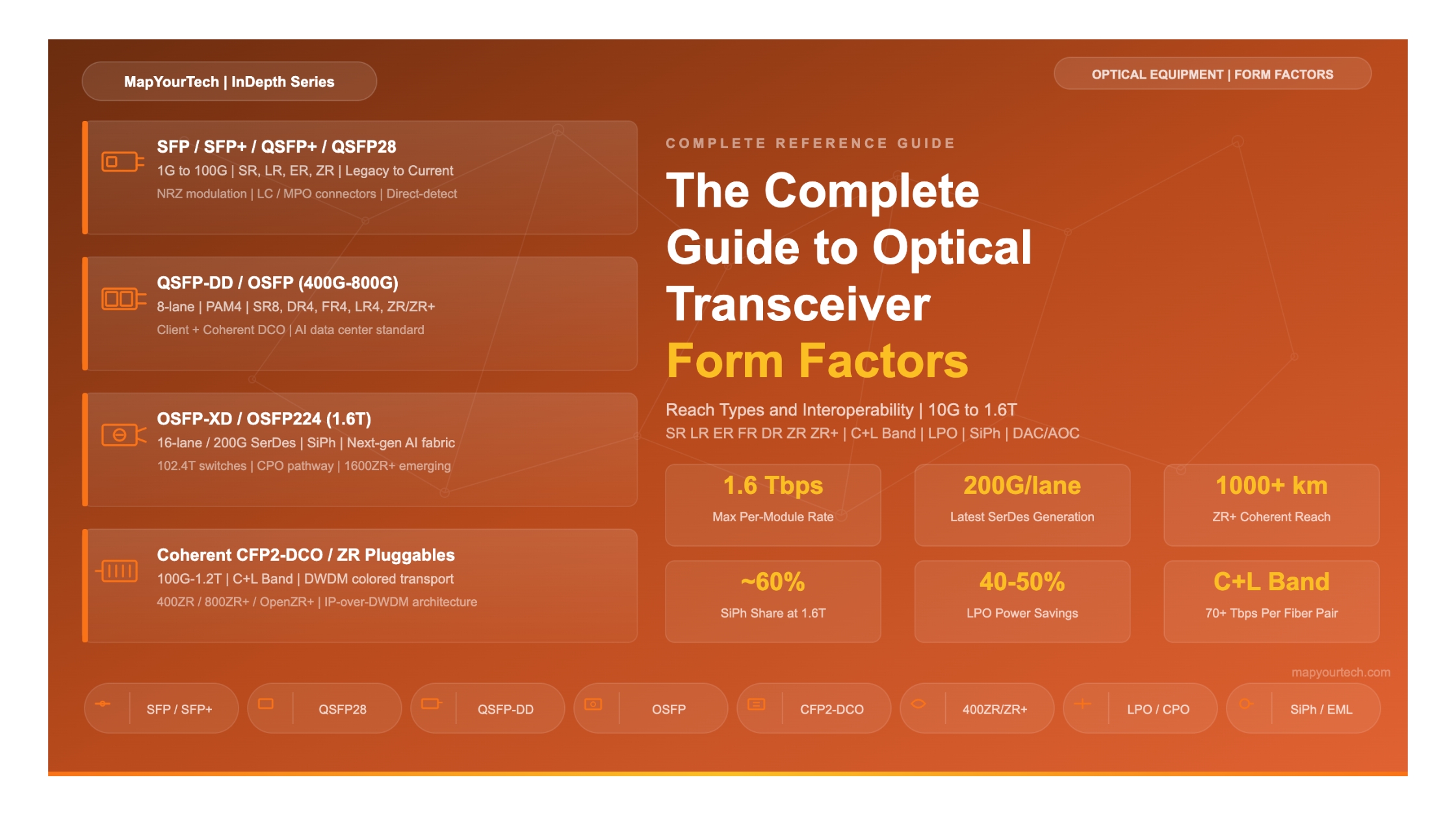

The Complete Guide to Optical Transceiver Form Factors, Reach Types, and Interoperability
SFP to OSFP-XD, 10G to 1.6T, SR through ZR+ -- covering every form factor, reach type, interop rule, and deployment decision across client, coherent, and emerging technologies
1. Executive Summary
The optical transceiver market is undergoing one of its most transformative periods. Driven by hyperscale data center expansion, AI/ML training cluster buildouts, and the relentless demand for bandwidth in telecom transport networks, the industry is simultaneously managing multiple generations of form factors, each optimized for different data rates, reach requirements, and power budgets. This strategic analysis examines how physical packaging, electrical interfaces, and optical reach designations intersect across the full spectrum of deployed and emerging data rates from 10G to 1.6T.
As of 2026, the market has consolidated around a few dominant form factors at each data rate. The Small Form-factor Pluggable (SFP) family remains the anchor for 1G through 25G applications. QSFP28 owns the 100G client space. QSFP-DD and OSFP share 400G and 800G duties, with OSFP gaining ground in new AI data center builds. On the coherent DWDM side, the Digital Coherent Optic (DCO) in CFP2 form factor is giving way to QSFP-DD DCO pluggables that can seat directly in routers. Looking forward, OSFP-XD is emerging as the preferred 1.6T carrier, while Co-Packaged Optics (CPO) waits in the wings for 3.2T and beyond.
The reach designations that accompany each transceiver tell operators exactly which fiber link budget the module supports. Short Reach (SR) modules use multimode fiber over distances up to a few hundred meters. Long Reach (LR) modules reach 10 km on single-mode fiber. Extended Reach (ER) covers 40 km, while Far Reach (FR) and Direct Reach (DR) address the 2 km and 500 m single-mode gaps respectively. For coherent applications, ZR (80-120 km) and ZR+ (hundreds to thousands of kilometers) define a new reach category that has reshaped metro and regional networking.
Executive Highlights
800G transceivers in OSFP and QSFP-DD form factors are the default choice for new AI data center builds as of 2026, with shipments projected to grow over 60% year-on-year.
1.6T modules using OSFP-XD and OSFP224 form factors are entering production, with 200G/lane SerDes becoming the next electrical interface standard.
The 400G ZR/ZR+ pluggable coherent revolution has successfully moved into 800G ZR/ZR+, with modules now available in QSFP-DD and OSFP form factors from multiple vendors.
Silicon Photonics (SiPh) accounts for approximately 40-45% of 800G transceiver production, rising toward 60% share in 1.6T modules.
2. Form Factor Fundamentals and Evolution
2.1 What Defines a Transceiver Form Factor?
A transceiver form factor defines three things: the mechanical housing (physical size, connector cage, latching mechanism), the electrical interface (number of lanes, SerDes rate per lane, signal encoding), and the thermal envelope (maximum power dissipation the package can safely handle). These three constraints together determine which data rates and optical reaches a given form factor can support. As data rates increase, the electrical lane count and the power budget must rise in tandem, and the mechanical design must provide enough volume for heat sinks and airflow channels.
The evolution of transceiver packaging has followed a general trend of miniaturization at each data rate. At 1G, the industry moved from the large GBIC module down to the SFP. At 10G, the XFP gave way to the smaller SFP+. At 40G, the QSFP+ established the quad-lane architecture that would define every subsequent generation. At 100G, the CFP was replaced by CFP2, then QSFP28. At 400G, two parallel form factors emerged: QSFP-DD (backward-compatible with QSFP cages) and OSFP (a clean-sheet design optimized for thermal headroom). At 800G and 1.6T, these same two families are scaling with higher-speed electrical interfaces.
2.2 Electrical Interface Evolution
The electrical interface between the transceiver and the host system has evolved through several generations. Early 10G modules used a single electrical lane with NRZ (Non-Return-to-Zero) modulation. The 25G SerDes generation powered QSFP28 (4 x 25G = 100G). The 50G PAM4 generation enabled QSFP-DD and OSFP to deliver 400G over 8 lanes (8 x 50G). As of 2026, the 100G SerDes generation supports 800G across 8 lanes (8 x 100G), and the 200G SerDes generation is entering production to enable 1.6T per module with 8 lanes (8 x 200G). Each doubling of per-lane rate allows either the same port density at double the speed, or double the density at the same speed.
| SerDes Rate | Encoding | Lanes | Aggregate BW | Primary Form Factors |
|---|---|---|---|---|
| 1G | NRZ | 1 | 1G | SFP |
| 10G | NRZ | 1 | 10G | SFP+, XFP |
| 25G | NRZ | 4 | 100G | QSFP28 |
| 50G | PAM4 | 4/8 | 200G/400G | QSFP56, QSFP-DD, OSFP |
| 100G | PAM4 | 4/8 | 400G/800G | QSFP112, QSFP-DD800, OSFP |
| 200G | PAM4 | 8 | 1.6T | OSFP-XD, OSFP224 |
2.3 Thermal and Mechanical Constraints
Power consumption is the single largest differentiator between QSFP-DD and OSFP at 800G and above. The QSFP-DD form factor has a width of approximately 18.4 mm and supports a thermal design power (TDP) of up to about 14-15 W with advanced cage designs, though some extended implementations push to 20W. OSFP, with its 22 mm width, accommodates integrated heat sinks and supports a thermal envelope of up to approximately 20W for 800G and 25-30W in the 1.6T OSFP-XD variant. For 400G coherent DCO modules, both form factors operate at 15-20W, which is why the QSFP-DD DCO at 400ZR works reliably at around 15W. However, at 800G coherent, the increased DSP complexity and laser power push consumption toward the upper boundary of what QSFP-DD can dissipate, making OSFP the preferred choice for 800G ZR+ applications requiring high output power.
3. Reach Classification Taxonomy
Every optical transceiver carries a reach designation that defines its target link distance, fiber type, and number of optical lanes. These reach codes are governed by IEEE 802.3 standards for Ethernet applications and by OIF/ITU-T specifications for coherent DWDM modules. Understanding these designations is essential for proper network design, as they dictate fiber infrastructure requirements, power budgets, and connector types.
| Code | Full Name | Fiber Type | Typical Distance | Wavelength | Common Rates |
|---|---|---|---|---|---|
| SR / SR4 / SR8 | Short Reach | Multimode (OM3/OM4) | 70-300 m | 850 nm (VCSEL) | 10G-400G |
| DR / DR1 / DR4 / DR8 | Direct Reach | Single-mode (G.652) | 500 m | 1310 nm | 100G-800G |
| FR / FR1 / FR4 | Far Reach | Single-mode (G.652) | 2 km | 1310 nm | 100G-400G |
| LR / LR1 / LR4 / LR8 | Long Reach | Single-mode (G.652) | 10 km | 1310 nm | 10G-400G |
| ER / ER4 | Extended Reach | Single-mode (G.652) | 40 km | 1310/1550 nm | 10G-100G |
| ZR (gray, direct-detect) | Very Long Reach | Single-mode (G.652) | 80 km | 1550 nm (fixed) | 10G (vendor-defined, not IEEE) |
| ZR (coherent, DWDM) | ZR (OIF / IEEE 802.3ct) | Single-mode DWDM | 80-120 km | C-band tunable (colored) | 100G, 400G, 800G |
| ZR+ | ZR+ (OpenZR+) | Single-mode DWDM | 120-1000+ km | C-band tunable | 400G-800G |
Read the Full Analysis with Premium
The remaining 89% of this article — the design numbers, trade-offs and field guidance — is part of MapYourTech Premium, along with the full premium library, courses and professional tools.


