
 in DWDM Networks")
Polarization Mode Dispersion (PMD) is one of the significant impairments in optical fiber communication systems, particularly in Dense Wavelength Division Multiplexing (DWDM) systems where multiple wavelengths (channels) are transmitted simultaneously over a single optical fiber. PMD occurs because of the difference in propagation velocities between two orthogonal polarization modes in the fiber. This difference results in a broadening of the optical pulses over time, leading to intersymbol interference (ISI), degradation of signal quality, and increased bit error rates (BER).
PMD is caused by imperfections in the optical fiber, such as slight variations in its shape, stress, and environmental factors like temperature changes. These factors cause the fiber to become birefringent, meaning that the refractive index experienced by light depends on its polarization state. As a result, light polarized in one direction travels at a different speed than light polarized in the perpendicular direction.
The Physics of PMD
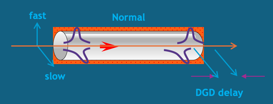
PMD arises from the birefringence of optical fibers. Birefringence is the difference in refractive index between two orthogonal polarization modes in the fiber, which results in different group velocities for these modes. The difference in arrival times between the two polarization components is called the Differential Group Delay (DGD).
The DGD is given by:
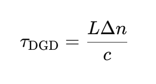
Where:
- L is the length of the fiber.
- Δn is the difference in refractive index between the two polarization modes.
- c is the speed of light in vacuum.
This DGD causes pulse broadening, as different polarization components of the signal arrive at the receiver at different times. Over long distances, this effect can accumulate and become a major impairment in optical communication systems.
Polarization Mode Dispersion and Pulse Broadening
The primary effect of PMD is pulse broadening, which occurs when the polarization components of the optical signal are delayed relative to one another. This leads to intersymbol interference (ISI), as the broadened pulses overlap with adjacent pulses, making it difficult for the receiver to distinguish between symbols. The amount of pulse broadening increases with the DGD and the length of the fiber.
The PMD coefficient is typically measured in ps/√km, which represents the DGD per unit length of fiber. For example, in standard single-mode fibers (SSMF), the PMD coefficient is typically around 0.05–0.5 ps/√km. Over long distances, the total DGD can become significant, leading to substantial pulse broadening.
Statistical Nature of PMD
PMD is inherently stochastic, meaning that it changes over time due to environmental factors such as temperature fluctuations, mechanical stress, and fiber bending. These changes cause the birefringence of the fiber to vary randomly, making PMD difficult to predict and compensate for. The random nature of PMD is usually described using statistical models, such as the Maxwellian distribution for DGD.
The mean DGD increases with the square root of the fiber length, as given by:
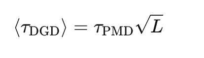
Where:
- τPMD is the PMD coefficient of the fiber.
- L is the length of the fiber.
PMD in Coherent Systems
In modern coherent optical communication systems, PMD can have a severe impact on system performance. Coherent systems rely on both the phase and amplitude of the received signal to recover the transmitted data, and any phase distortions caused by PMD can lead to significant degradation in signal quality. PMD-induced phase shifts lead to phase noise, which in turn increases the bit error rate (BER).
Systems using advanced modulation formats, such as Quadrature Amplitude Modulation (QAM), are particularly sensitive to PMD, as these formats rely on accurate phase information to recover the transmitted data. The nonlinear phase noise introduced by PMD can interfere with the receiver’s ability to correctly demodulate the signal, leading to increased errors.
Formula for PMD-Induced Pulse Broadening
The pulse broadening due to PMD can be expressed as:
Where:
- τDGD is the differential group delay.
- L is the fiber length.
This equation shows that the amount of pulse broadening increases with both the DGD and the fiber length. Over long distances, the cumulative effect of PMD can cause significant ISI and degrade system performance.
Detecting PMD in DWDM Systems
Engineers can detect PMD in DWDM networks by monitoring several key performance indicators (KPIs):
- Increased Bit Error Rate (BER): PMD-induced phase noise and pulse broadening lead to higher BER, particularly in systems using high-speed modulation formats like QAM.
-
-
-
-
- KPI: Real-time BER monitoring. A significant increase in BER, especially over long distances, is a sign of PMD.
-
-
-
-
- Signal-to-Noise Ratio (SNR) Degradation: PMD introduces phase noise and pulse broadening, which degrade the SNR. Operators may observe a drop in SNR in the affected channels.
-
-
-
-
- KPI: SNR monitoring tools that provide real-time feedback on the quality of the transmitted signal.
-
-
-
-
- Pulse Shape Distortion: PMD causes temporal pulse broadening and distortion. Using an optical sampling oscilloscope, operators can visually inspect the shape of the transmitted pulses to identify any broadening caused by PMD.
- Optical Spectrum Analyzer (OSA): PMD can lead to spectral broadening of the signal, which can be detected using an OSA. The analyzer will show the broadening of the spectrum of the affected channels, indicating the presence of PMD.
Mitigating PMD in DWDM Systems
Several strategies can be employed to mitigate the effects of PMD in DWDM systems:
- PMD Compensation Modules: These are adaptive optical devices that compensate for the differential group delay introduced by PMD. They can be inserted periodically along the fiber link to reduce the total accumulated PMD.
- Digital Signal Processing (DSP): In modern coherent systems, DSP techniques can be used to compensate for the effects of PMD at the receiver. These methods involve applying adaptive equalization filters to reverse the effects of PMD.
- Fiber Design: Fibers with lower PMD coefficients can be used to reduce the impact of PMD. Modern optical fibers are designed to minimize birefringence and reduce the amount of PMD.
- Polarization Multiplexing: In polarization multiplexing systems, PMD can be mitigated by separating the signals transmitted on orthogonal polarization states and applying adaptive equalization to each polarization component.
- Advanced Modulation Formats: Modulation formats that are less sensitive to phase noise, such as Differential Phase-Shift Keying (DPSK), can help reduce the impact of PMD on system performance.
Polarization Mode Dispersion (PMD) is a critical impairment in DWDM networks, causing pulse broadening, phase noise, and intersymbol interference. It is inherently stochastic, meaning that it changes over time due to environmental factors, making it difficult to predict and compensate for. However, with the advent of digital coherent optical systems and DSP techniques, PMD can be effectively managed and compensated for, allowing modern systems to achieve high data rates and long transmission distances without significant performance degradation.
Summary
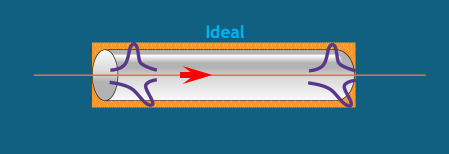
- Different polarization states of light travel at slightly different speeds in a fiber, causing pulse distortion.
- This variation can cause pulses to overlap or alter their shape enough to become undetectable at the receiver.
- PMD occurs when the main polarization mode travels faster than the secondary mode, causing a delay known as Differential Group Delay (DGD).
- PMD becomes problematic at higher transmission rates like 10, 40 or 100 Gbps etc.
- Unlike chromatic dispersion, PMD is a statistical, non-linear phenomenon, making it more complex to manage.
- PMD is caused by fiber asymmetry due to geometric imperfections, stress from the wrapping material, manufacturing processes, or mechanical stress during cable laying.
- PMD is the average value of DGD distributions, which vary over time, and thus cannot be directly measured in the field.
Reference
- https://www.wiley.com/en-ie/Fiber-Optic+Communication+Systems%2C+5th+Edition-p-9781119737360

