17 min read
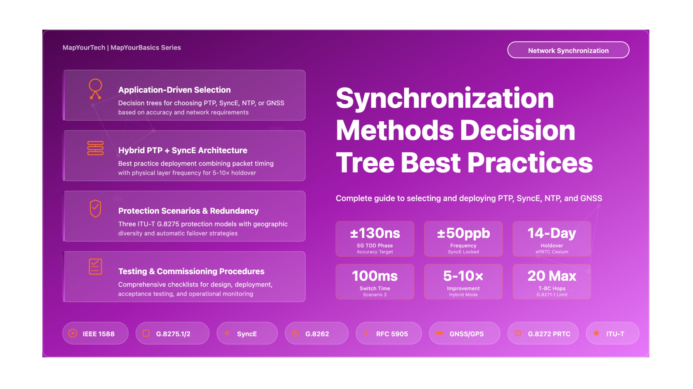
Best Practices: Synchronization Methods Decision Tree
A Comprehensive Guide to Selecting PTP, SyncE, NTP, and GNSS for Telecom Networks
Introduction
Network synchronization has become one of the most critical yet complex aspects of modern telecommunications infrastructure. As networks evolve to support 5G Time Division Duplex (TDD) operations, time-sensitive networking applications, and distributed cloud architectures, the selection of appropriate synchronization methods can determine whether a deployment succeeds or fails to meet service level agreements.
This best practices guide provides a structured decision framework for selecting and deploying synchronization technologies across four primary methods: Precision Time Protocol (PTP/IEEE 1588), Synchronous Ethernet (SyncE), Network Time Protocol (NTP), and Global Navigation Satellite Systems (GNSS) including GPS, GLONASS, Galileo, and BeiDou. The document addresses the fundamental question network architects face: which synchronization method should be deployed where, and under what circumstances should hybrid approaches be used?
The guidance presented here synthesizes requirements from ITU-T Recommendations G.8271 through G.8275.2, IEEE 1588-2019, and operational experience from carrier-grade network deployments. The focus extends beyond simple technology comparison to address practical implementation challenges including holdover requirements, protection switching strategies, oscillator selection, and the critical tradeoffs between capital expenditure, operational complexity, and timing accuracy.
Master Synchronization Decision Tree
The following decision tree provides a visual framework for selecting the optimal synchronization method based on your specific network requirements, constraints, and application needs. Start at the top and follow the decision path through each question to reach the recommended solution for your deployment scenario.
1. Fundamental Principles
1.1 Understanding Synchronization Requirements
Before selecting synchronization methods, engineers must clearly differentiate between the three fundamental types of synchronization that network applications require. These requirements are not interchangeable, and selecting the wrong synchronization type leads to service degradation or complete application failure.
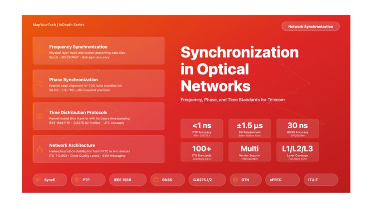
Frequency Synchronization ensures that two clocks operate at precisely the same rate, measured in parts per billion (ppb) or fractional frequency offset. A network element receiving frequency synchronization can generate clock signals at exactly the same rate as the reference source, preventing buffer overflow or underflow in Time Division Multiplexing (TDM) circuit emulation and maintaining proper sampling rates in digital signal processing. Frequency synchronization alone provides no information about absolute time or the phase relationship between clock edges at different locations. The ITU-T G.811 Primary Reference Clock specification requires frequency accuracy within ±1×10⁻¹¹ over long averaging periods, which Synchronous Ethernet naturally supports through its physical layer distribution mechanism.
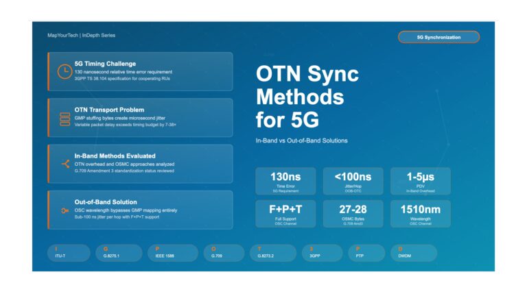
Phase Synchronization aligns the edges of clock signals at different network locations, ensuring that the rising or falling transitions of clock waveforms occur within a specified time window relative to each other. This requirement emerges in Time Division Duplex radio systems where base stations must coordinate their transmit and receive windows to prevent interference. The 5G fronthaul specification in ITU-T G.8271.1 mandates phase alignment within ±130 nanoseconds between radio units in the same cluster. Phase synchronization inherently includes frequency synchronization since maintaining aligned clock edges requires matching clock rates, but the reverse is not true.
Time-of-Day Synchronization provides absolute time information traceable to Coordinated Universal Time (UTC), allowing network elements to timestamp events with globally consistent wall-clock time. Applications requiring time-of-day synchronization include financial transaction timestamping (MiFID II compliance), security log correlation across distributed systems, and mobile handover timing coordination. The ITU-T G.8272 PRTC-A specification requires time accuracy within ±100 nanoseconds of UTC, achievable through GNSS receivers with proper antenna placement and signal quality.
Synchronization Types Visual Comparison
The following diagram illustrates the fundamental differences between the three types of synchronization and shows which technologies can deliver each type. Understanding these distinctions is essential for proper architecture selection.
1.2 Accuracy Hierarchy and Error Budgets
Network synchronization operates as a hierarchical distribution system where timing accuracy degrades as signals pass through network elements from the primary reference source to end applications. Each network element in the timing chain contributes noise, packet delay variation, or wander that accumulates along the path. Proper network design requires calculating the end-to-end timing error budget and ensuring that cumulative errors remain within application tolerance.
The accuracy hierarchy begins with primary reference timing sources. Enhanced Primary Reference Time Clocks (ePRTC) meeting ITU-T G.8272.1 specifications provide the highest quality timing with ±100 nanoseconds maximum absolute time error to UTC and holdover capability maintaining ±100 nanoseconds for 14 days when GNSS signals become unavailable. These clocks typically combine multi-constellation GNSS receivers with cesium atomic oscillators. Standard PRTC clocks meeting G.8272 PRTC-A requirements achieve ±100 nanoseconds during normal operation but rely on lower-grade oscillators with hours rather than days of holdover capability.
As timing distributes through the network, ITU-T defines performance classes for intermediate timing equipment. T-BC (Telecom Boundary Clock) and T-TSC (Telecom Time Slave Clock) devices meeting G.8273.2 Class C requirements must maintain time error within ±70 nanoseconds in steady state and meet specific MTIE (Maximum Time Interval Error) and TDEV (Time Deviation) masks during transient conditions. Class D requirements tighten these specifications to ±40 nanoseconds for applications requiring sub-50 nanosecond phase alignment at the end application.
Time Error Budget Calculation:

TE_total = TE_PRTC + TE_network + TE_slave

Where:
TE_PRTC    = Primary reference time error (typically ±30 to ±50 ns)
TE_network = Accumulated network noise (N_hops × TE_per_hop)
TE_slave   = End application clock performance (±10 to ±30 ns)

Example for 5G Fronthaul (±130 ns phase error limit):
TE_total = 40 ns (PRTC) + (10 hops × 5 ns/hop) + 20 ns (slave) = 110 ns
Result: Meets ±130 ns requirement with 20 ns margin
Network designs must limit hop counts and packet delay variation to stay within error budgets. ITU-T G.8271.1 specifies maximum chain lengths of 20 T-BC devices for 5G fronthaul Class C applications, though practical deployments often limit chains to 10-12 hops to provide safety margin for variations in network loading and fiber asymmetry. Each additional hop adds both constant delay asymmetry (from different transmit and receive path delays) and time-varying packet delay variation that the slave clock must filter.
1.3 Holdover Requirements and Oscillator Selection
Holdover capability determines how long a network element can maintain acceptable timing accuracy after losing its timing reference. When GNSS signals become unavailable due to jamming, antenna failure, or atmospheric conditions, or when packet network connectivity to timing masters fails, network elements enter holdover mode where their local oscillators provide timing without external correction. The quality of this local oscillator directly determines holdover duration before timing errors exceed application tolerances.
Temperature Compensated Crystal Oscillators (TCXO) represent the lowest cost option commonly deployed in radio equipment and small cell base stations. Without frequency support from Synchronous Ethernet, TCXO oscillators typically drift beyond ±1.5 microsecond phase error in minutes, making them unsuitable for extended GNSS outages. However, when supported by SyncE frequency distribution, the same TCXO can maintain phase accuracy for hours because its frequency remains locked while only the phase drifts during the PTP outage.
Oven Controlled Crystal Oscillators (OCXO) provide superior stability through temperature regulation of the crystal element, achieving fractional frequency stability of 1×10⁻¹⁰ to 1×10⁻¹¹ over short to medium averaging periods. OCXO-equipped network switches and Distributed Unit (DU) equipment typically maintain phase accuracy within ±1.5 microseconds for approximately 3 hours without external frequency reference, or 8+ hours when supported by SyncE. This performance makes OCXO the standard choice for aggregation and core network timing elements.
Rubidium atomic oscillators deliver fractional frequency stability of 1×10⁻¹¹ to 1×10⁻¹² over holdover periods measured in days. Telecom Grandmaster (T-GM) clocks equipped with rubidium oscillators and SyncE support can maintain sub-microsecond phase accuracy for multiple days during GNSS outages, providing sufficient holdover for site maintenance or antenna repairs before operator intervention becomes necessary. The higher cost of rubidium oscillators limits their deployment to critical aggregation sites and mobile switching centers where extended holdover justifies the investment.
Hybrid PTP + SyncE Architecture Visualization
Understanding how PTP and SyncE work together in hybrid mode is essential for appreciating why this architecture delivers superior performance. The following diagram shows the signal flow and interactions between both protocols operating simultaneously on the same physical infrastructure.
1.4 Protection Architectures and Redundancy Models
Telecom synchronization networks require the same level of protection and redundancy as service-carrying traffic paths. Three protection scenarios define the standard approaches documented in ITU-T G.8275 for packet-based time distribution, each addressing different failure modes and recovery objectives.
Protection Scenario 1: Long-Term Holdover with Physical Layer Frequency Support applies when no backup timing master is available but SyncE provides frequency distribution. When the PTP timing path fails, the end application or intermediate timing equipment enters holdover mode while maintaining frequency lock through SyncE. This scenario supports holdover periods of hours to days depending on local oscillator quality. The advantage lies in simplicity since no timing path switching occurs, but it requires SyncE deployment throughout the network and oscillators capable of extended holdover. This approach suits network segments where deploying redundant timing masters is economically unfeasible, such as rural cell sites or enterprise customer premises.
Protection Scenario 2: Switching to Backup Reference with Physical Layer Frequency Support provides active redundancy by maintaining connections to both primary and backup timing masters. When the primary PTP path fails or degrades below quality thresholds, the slave clock switches to the backup master while maintaining frequency lock through SyncE. The frequency support minimizes phase transients during the switchover, keeping phase error within ±50 nanoseconds during the protection switching interval. This scenario requires dual timing master deployment with geographic diversity to protect against site failures, but the SyncE frequency reference ensures hitless or nearly hitless switching from the application perspective. Core and aggregation network segments typically implement this protection level.
Protection Scenario 3: Switching to Backup Reference Without Physical Layer Frequency Support addresses brownfield networks where SyncE deployment is infeasible due to legacy equipment or third-party network segments. During timing master switchover, the slave clock relies solely on its local oscillator holdover without frequency support, potentially causing larger phase transients. Meeting ±1.5 microsecond phase error requirements during switching necessitates high-quality local oscillators (OCXO or rubidium) and fast failure detection to minimize holdover duration. This scenario represents the minimum acceptable protection level for phase-critical applications but introduces higher equipment cost and longer service impact during failures compared to SyncE-supported protection.
ITU-T G.8275 Protection Scenarios Comparison
ITU-T G.8275 defines three standard protection scenarios that address different failure modes and recovery objectives. Understanding which scenario applies to your deployment determines equipment requirements, expected recovery times, and operational procedures during timing failures.
2. Design Best Practices
2.1 Application-Driven Architecture Selection
Synchronization architecture selection begins with comprehensive analysis of application requirements across the network. Different network segments often require different synchronization approaches, and attempting to deploy a single uniform solution across all segments typically results in either over-engineering (excessive cost) or under-engineering (inadequate performance) for specific use cases.
5G Radio Access Network Synchronization
The 5G fronthaul segment connecting Distributed Units (DU) to Radio Units (RU) imposes the most demanding timing requirements in commercial telecommunications, mandating phase alignment within ±130 nanoseconds between radio units in the same Time Division Duplex cluster. This requirement eliminates NTP as a viable solution and makes GNSS-only approaches operationally risky due to jamming vulnerability.
The recommended architecture combines ITU-T G.8275.1 PTP Profile with full timing support and SyncE frequency distribution (G.8262.1 with Enhanced Ethernet Equipment Clock specifications). Central offices or edge data centers host ePRTC equipment with multi-constellation GNSS receivers, cesium oscillators for extended holdover, and dual geographic redundancy. PTP messages traverse the aggregation network using Layer 2 multicast transport through T-BC boundary clocks meeting G.8273.2 Class C or Class D specifications. Every Ethernet link in the fronthaul path must support SyncE to provide frequency stability during PTP transients or holdover periods.
This hybrid PTP plus SyncE architecture achieves several critical objectives simultaneously: phase accuracy meets 5G TDD requirements with margin for network variations; frequency stability from SyncE extends holdover duration 5-10× compared to PTP-only designs; hardware timestamping in boundary clocks compensates for packet delay variation from network congestion; and protection switching between redundant timing masters completes within milliseconds with minimal phase transients.
Mobile Backhaul and Enterprise Access
Mobile backhaul networks connecting cell sites to mobile packet core equipment typically face less stringent timing requirements than fronthaul, with frequency accuracy of ±50 ppb often sufficient for 4G LTE and early 5G Non-Standalone deployments. However, network operators often lease backhaul capacity from third-party providers without control over intermediate switching equipment, preventing deployment of PTP-aware boundary clocks.
For these scenarios, ITU-T G.8275.2 PTP Profile with Assisted Partial Timing Support (APTS) provides the optimal compromise. Cell sites deploy local GNSS receivers as primary timing sources, reducing dependence on backhaul network timing quality. A secondary PTP timing path operates over Layer 3 unicast IPv4 or IPv6, allowing transit through standard routers without timing support. The local GNSS receiver assists PTP by calibrating path asymmetry, improving accuracy over pure packet-based timing while providing backup during GNSS outages.
This architecture sacrifices the superior accuracy and holdover of full timing support (G.8275.1) but gains the ability to deploy over brownfield networks without requiring hardware upgrades across the entire transport path. Capital expenditure shifts from core network timing equipment to edge GNSS receivers, often a favorable tradeoff for mobile network operators focused on rapid 5G small cell densification.
Data Center and Financial Services
Data center environments supporting distributed databases, high-frequency trading, or regulatory compliance timestamping require both high accuracy (sub-microsecond) and low latency (sub-microsecond distribution delay). Unlike mobile networks with geographic dispersion, data centers consolidate equipment within facilities where fiber lengths remain short and controlled.
Enterprise PTP profiles (IEEE 1588 default profile or IETF Enterprise Profile RFC 9760) operate over standard Ethernet LANs with software or hardware timestamping depending on accuracy requirements. For extreme accuracy applications, White Rabbit protocol achieving sub-nanosecond synchronization extends IEEE 1588-2019 with bidirectional wavelength-division multiplexing fiber that eliminates asymmetry uncertainty. Financial trading platforms increasingly deploy dedicated PTP networks with GPS-disciplined grandmaster clocks at each facility, ensuring MiFID II compliance for transaction timestamping within 100 microseconds of UTC.
NTP retains relevance in data center server synchronization where millisecond accuracy suffices for log file correlation, distributed debugging, and non-critical application timing. The lower complexity and universal operating system support make NTP suitable for mass server deployment, reserving PTP for systems with stringent accuracy requirements.
If application requires only frequency synchronization: Deploy SyncE (ITU-T G.8262) as the primary method with packet-based backup (PTP per G.8265.1 or NTP). SyncE provides superior frequency stability, immunity to packet network impairments, and low operational complexity. This approach suits TDM circuit emulation, some packet voice gateways, and legacy equipment requiring frequency references.
If application requires phase or time-of-day synchronization: Packet-based methods (PTP) or GNSS become necessary. SyncE alone cannot provide phase alignment. The choice between PTP, GNSS, or hybrid depends on accuracy requirements, capital expenditure constraints, and network ownership boundaries as detailed in subsequent decision nodes.
2.2 Packet Network Characterization and PDV Management
Packet Delay Variation (PDV) represents the primary challenge in achieving high-accuracy packet-based timing. PDV arises from packet queueing in switches and routers, where multiple traffic flows compete for the same output port. While the average propagation delay through a network element might be stable at 10 microseconds, individual packets experience delays ranging from 10 to 500 microseconds depending on instantaneous queue depth. This variation directly impacts PTP synchronization accuracy since timing calculations assume symmetric paths with stable delay.
Network characterization for timing deployment requires measuring PDV across the paths that will carry PTP traffic, not just verifying average latency or packet loss. Tools such as PTP-enabled test equipment or software probes measure the floor delay (minimum packet transit time representing the propagation delay without queueing) and the PDV range (difference between maximum and minimum observed delays). ITU-T G.8271 specifies PDV limits that T-BC devices must handle: Class C boundary clocks must maintain time error within specification when subjected to packet delay variation up to 25 milliseconds peak-to-peak.
Practical PDV management employs multiple complementary strategies. Quality of Service (QoS) configuration gives PTP packets priority treatment, mapping them to the highest priority queue (typically Differentiated Services Code Point EF - Expedited Forwarding) to minimize queueing delay behind bulk data traffic. Many modern switches support PTP-aware Quality of Service where PTP packets automatically receive the highest priority without explicit configuration, though verifying this behavior during commissioning remains essential since implementations vary.
Traffic engineering reduces background traffic loads on links carrying timing traffic, keeping link utilization below 70% on timing-critical paths to prevent sustained queueing. In aggregation networks, deploying dedicated timing VLANs or MPLS label-switched paths isolates PTP traffic from user data, preventing bursty customer traffic from impacting timing message delivery. The additional bandwidth cost proves negligible since PTP generates only 64-256 packets per second depending on message rate configuration.
2.3 Hybrid Architecture Implementation
Hybrid synchronization combining PTP and SyncE delivers superior performance compared to either technology deployed independently, representing the current industry best practice for networks requiring phase synchronization. The architecture leverages each technology's strengths: SyncE provides rock-solid frequency stability through physical layer clocking immune to packet network impairments, while PTP delivers phase and time-of-day information that SyncE alone cannot provide.
Implementation requires careful attention to clock mode configuration and holdover behavior. Network elements supporting hybrid operation implement independent frequency and phase recovery loops. The frequency loop locks to SyncE, recovering a clean frequency reference from the Ethernet line coding that drives the local oscillator. This frequency locks the time recovery loop, which processes PTP messages to align clock phase. During PTP message loss or network isolation, the phase loop enters holdover while frequency lock through SyncE continues, dramatically extending the duration before phase error exceeds application tolerances.
The most common hybrid mode implementation uses ITU-T G.8275.1 PTP profile over Synchronous Ethernet links meeting G.8262.1 enhanced EEC specifications. This combination provides frequency accuracy better than ±50 ppb even during phase transients, phase accuracy better than ±100 nanoseconds in steady state, and holdover extending from minutes to hours depending on local oscillator quality. The architecture requires that every link in the timing path support both protocols - deploying SyncE on only some links eliminates the frequency support advantage.
Hybrid Mode Best Practices
Common Hybrid Mode Mistakes
3. Implementation Guidelines
3.1 GNSS Deployment Considerations
Global Navigation Satellite System receivers provide the ultimate timing reference for most telecom synchronization networks, delivering traceability to UTC with accuracy within ±30 nanoseconds under optimal conditions. However, GNSS-based timing introduces operational challenges that must be addressed through proper site selection, equipment configuration, and protection architectures.
Antenna Site Selection and Installation
GNSS antenna placement determines receiver performance and represents the single most common source of timing degradation in field deployments. Antennas require unobstructed hemispherical sky visibility with elevation angles down to 10-15 degrees above the horizon to track satellites across their visible paths. Mounting antennas inside buildings, under metallic canopies, or adjacent to tall structures creates multipath reflections where satellite signals bounce off surfaces before reaching the antenna, introducing timing errors of 10-100 nanoseconds and causing intermittent loss of signal lock.
Proper antenna installations place the antenna on rooftops or dedicated masts with minimum 3 meters clearance from any vertical obstruction. The antenna mounting structure must be mechanically stable since even millimeter-level vibration translates to nanosecond timing jitter. Cable runs from antenna to receiver should minimize length (typically under 50 meters for passive antennas) and use high-quality low-loss coaxial cable with properly installed connectors. Many timing receivers support active antennas with integrated low-noise amplifiers, allowing cable runs up to 100-150 meters while maintaining signal quality.
Lightning protection represents a critical but often overlooked aspect of outdoor antenna installations. Implementing inline surge protection on antenna cables protects receiver electronics from lightning-induced voltage spikes while introducing minimal signal attenuation. Grounding both the antenna structure and surge protector to site earth ground following local electrical codes prevents ground loops that cause timing noise.
Multi-Constellation and Multi-Band Receiver Configuration
Modern GNSS receivers support multiple satellite constellations (GPS, GLONASS, Galileo, BeiDou) and multiple frequency bands (GPS L1/L2/L5). Enabling multi-constellation tracking increases the number of simultaneously visible satellites from 8-12 for GPS-only to 20-30 for all constellations combined, improving solution availability in challenging signal environments such as urban canyons or partial obstructions. However, multi-constellation operation introduces complexity in receiver configuration and satellite almanac management.
Multi-band receivers using GPS L1 and L5 frequencies simultaneously provide inherent protection against ionospheric delay variations that single-frequency receivers must model. The ionosphere, an ionized layer of Earth's atmosphere, affects satellite signal propagation velocity in a frequency-dependent manner. By measuring the differential delay between L1 (1575.42 MHz) and L5 (1176.45 MHz) signals from the same satellite, receivers directly compute and correct for ionospheric delay rather than relying on broadcast models. This capability becomes especially valuable during geomagnetic storms when ionospheric activity increases and single-frequency model accuracy degrades.
For timing applications requiring traceability to UTC, receivers should be configured to track UTC time transfer signals rather than GNSS system time. Each GNSS constellation maintains its own system time (GPS Time, GLONASS Time, Galileo System Time, BeiDou Time) which relates to but does not precisely equal UTC. UTC time transfer broadcast by GPS satellites carries explicit offset information relating GPS Time to UTC(USNO), enabling receivers to output 1PPS signals and time-of-day messages referenced to UTC rather than GPS Time. This configuration ensures consistency with ITU-T standards which specify all timing performance relative to UTC.
GNSS Vulnerability Mitigation
GNSS signals arrive at Earth's surface with extremely low power (approximately -130 dBm), making them vulnerable to both intentional jamming and unintentional interference. A low-power transmitter operating anywhere in the GNSS frequency bands can overload nearby receivers, causing loss of timing lock. Proper deployment architectures must assume that GNSS outages will occur and design accordingly.
Enhanced PRTC (ePRTC) meeting ITU-T G.8272.1 specifications pairs GNSS receivers with cesium atomic oscillators, providing 14-day holdover capability maintaining ±100 nanoseconds accuracy to UTC even during complete GNSS outage. While cesium oscillators add significant cost (typically $50,000-100,000 USD per site), deploying them at a small number of strategic aggregation sites protects the entire network timing hierarchy. During GNSS outage at an ePRTC site, downstream network elements continue receiving timing via PTP or SyncE with minimal degradation, unaware that the ultimate reference has entered holdover.
Geographic redundancy distributes multiple GNSS-equipped timing sources across separated locations exceeding 50-100 kilometers apart, reducing the probability that a single jamming source affects all references simultaneously. ITU-T recommends east-west rather than north-south separation since many GNSS jamming incidents originate from mobile sources traveling along ground transportation corridors. Network elements in geographic redundancy architectures maintain timing connections to at least two spatially separated grandmaster clocks, automatically switching to the alternate source if primary timing degrades.
3.2 PTP Profile Selection and Configuration
IEEE 1588 defines a framework for precision time protocol, but the standard intentionally leaves numerous parameters and behaviors as implementation choices. PTP profiles specify mandatory parameter values and behavioral requirements to ensure interoperability between equipment from different vendors. Selecting the appropriate profile for the deployment scenario determines not only whether equipment can synchronize but also the achievable accuracy and operational characteristics.
ITU-T G.8275.1 Full Timing Support Profile
G.8275.1 represents the optimal choice for networks where the operator controls all intermediate network elements and can deploy PTP-aware boundary clocks at each switching point. The profile mandates Layer 2 multicast PTP message transport over Ethernet networks, hardware-based timestamping with accuracy better than 8 nanoseconds, and on-path support where every switch acts as a T-BC boundary clock terminating and regenerating PTP messages.
Key configuration parameters for G.8275.1 deployments include PTP domain number (typically 24 for frequency-only distribution or 44 for phase/time distribution), announce message interval (typically 1 second for stability), sync and delay request intervals (configurable from 0.125 seconds to 16 seconds depending on accuracy requirements and PDV sensitivity), and priority settings that establish grandmaster hierarchy. The profile explicitly prohibits the Best Master Clock Algorithm (BMCA) dynamic reconfiguration, requiring instead manually engineered timing trees where grandmaster roles remain fixed and timing flow direction never reverses.
Protection configuration within G.8275.1 allows slave clocks to maintain connections to multiple grandmasters simultaneously, typically using a 1:1 or 1:N protection model. The slave continuously monitors Quality Level (QL) messages from all connected masters through PTP Announce messages carrying ITU-T G.781 clock quality information. Upon detecting quality degradation (QL value decrease) or communication loss from the active master, the slave switches to an alternate master within 100-200 milliseconds. When deployed with hybrid PTP plus SyncE architecture, SyncE maintains frequency lock during the switchover, limiting phase transients to ±50 nanoseconds in well-designed networks.
ITU-T G.8275.2 Partial Timing Support Profile
G.8275.2 addresses scenarios where intermediate network elements lack PTP support, common in enterprise networks, mobile backhaul over leased lines, or brownfield infrastructure awaiting upgrade. The profile uses Layer 3 unicast PTP transport over IPv4 or IPv6, allowing PTP messages to transit standard routers without timing support. Since routers introduce variable packet delay without boundary clock PDV compensation, G.8275.2 achieves lower accuracy than G.8275.1 in equivalent network conditions.
Assisted Partial Timing Support (APTS) represents the G.8275.2 deployment model offering the best accuracy in partial timing networks. Edge sites deploy local GNSS receivers serving as primary timing sources, with backup PTP connections to remote grandmasters over the IP network. The local GNSS assists timing accuracy in two ways: during normal operation, it provides reference timing for calibrating asymmetry in the PTP path, improving the accuracy of the backup source; during GNSS outage, the equipment maintains timing lock through the PTP backup path previously calibrated against known-good GNSS timing.
G.8275.2 configuration differs substantially from G.8275.1 in several aspects. Unicast negotiation requires slaves to explicitly request timing service from masters through unicast negotiation messages, establishing a contract for message rates and duration. Masters may accept or reject requests based on capacity limits or administrative policies. Message rates typically configure slower than G.8275.1 (2-8 seconds per sync interval) since slaves lacking on-path support must perform extensive filtering to extract timing from noisier packet streams. Slave selection logic must account for path characteristics when choosing between multiple available masters, often preferring paths with lower PDV even if competing paths offer slightly better clock quality.
Enterprise and White Rabbit Profiles
Enterprise PTP profiles target data center and industrial automation deployments where equipment resides within controlled facilities connected by short fiber runs or copper cables. The default IEEE 1588 profile and IETF Enterprise Profile (RFC 9760) simplify configuration by enabling BMCA automatic master selection, allowing plug-and-play deployments where the best available timing source automatically becomes grandmaster without manual configuration. While this flexibility aids initial deployment, it can cause operational disruption if a device with better clock quality connects to the network and triggers grandmaster switchover, causing all slaves to resynchronize simultaneously.
White Rabbit, specified in IEEE 1588-2019 Annex L as the High Accuracy Profile, achieves sub-nanosecond synchronization accuracy through several enhancements over standard PTP. The protocol uses dedicated bidirectional fiber strands with different wavelengths for transmit and receive directions, allowing precise measurement and compensation of fiber asymmetry. Digital timestamping accuracy improves through averaging multiple timestamps per second and applying temperature-compensated fixed delays for all electronic components in the path. While White Rabbit requires specialized equipment and cannot operate over standard Ethernet infrastructure, it finds application in scientific instrumentation, particle accelerators, and financial trading infrastructure where nanosecond precision justifies the deployment complexity.
| Scenario | Recommended Profile | Key Considerations |
|---|---|---|
| 5G fronthaul, operator-controlled network | G.8275.1 + SyncE | Meets ±130ns phase requirement, full redundancy support |
| Mobile backhaul over leased capacity | G.8275.2 with APTS | Local GNSS compensates for lack of on-path support |
| Enterprise data center, controlled environment | Enterprise Profile or Default | Automatic master selection, simplified deployment |
| Financial trading, extreme accuracy | White Rabbit (Annex L) | Sub-nanosecond accuracy justifies specialized equipment |
| Legacy network with limited PTP support | G.8275.2 unicast | Operates over standard IP, accepts lower accuracy |
3.3 SyncE Deployment and Quality Level Management
Synchronous Ethernet provides frequency synchronization by recovering clock timing directly from the Ethernet physical layer signal, analogous to SONET/SDH clock recovery but applied to Ethernet. Unlike packet-based timing methods, SyncE operates independently of network congestion, packet loss, or Layer 2/3 protocol behavior, providing deterministic frequency transfer with zero packet delay variation sensitivity.
Physical Layer Requirements
SyncE deployment requires that every switch and router in the timing chain support IEEE 802.3 Synchronous Ethernet specifications and ITU-T G.8262 Ethernet Equipment Clock (EEC) requirements. The equipment must implement clock recovery circuits that extract timing from the Ethernet line coding (specifically from the recovered clock at 125 MHz for Gigabit Ethernet and 10 GHz for 10 Gigabit Ethernet), filter the extracted timing to remove jitter, and use the recovered frequency to discipline a local oscillator that clocks transmit interfaces.
Not all Ethernet equipment supports SyncE even if marketing literature suggests "timing support." Verification during procurement requires confirming specific ITU-T G.8262 or G.8262.1 compliance, not just general "synchronization capability." G.8262 defines basic EEC requirements with holdover specifications supporting traditional Stratum 3/4 applications, while G.8262.1 enhanced EEC (eEEC) tightens specifications to support 5G timing requirements with improved noise generation and faster transient response.
Quality Level Propagation with ESMC
The Ethernet Synchronization Messaging Channel (ESMC), defined in ITU-T G.8264, distributes clock quality information across the SyncE network using standard Ethernet slow protocols (IEEE 802.3 Organization Specific Slow Protocol, OSSP). ESMC messages carry ITU-T G.781 quality level values indicating the traceability of the timing source: QL-PRC indicates direct connection to a Primary Reference Clock; QL-SSU-A through QL-SSU-B indicate various synchronization supply unit quality levels; QL-DNU (Do Not Use) marks timing that should not be used for synchronization.
Quality level information enables automatic protection switching in SyncE networks. Each network element configured for SyncE operation receives ESMC messages on all its timing-capable interfaces, compares the received quality levels, and selects the best available source following QL hierarchy. Upon detecting quality degradation or loss of ESMC from the active timing source, the equipment automatically switches to an alternate source with the next-best quality level, typically completing the switch in 50-200 milliseconds.
Proper ESMC configuration prevents timing loops, a failure mode unique to physical layer synchronization. Timing loops occur when two or more network elements select each other as timing sources, creating a circular dependency where no element references the primary timing source. The loop continues operating temporarily with all elements slowly drifting based on their free-running oscillator accuracy, but timing quality degrades until applications fail. ESMC configuration must implement Do-Not-Use marking on interfaces that should never be timing sources (such as customer-facing ports) and careful quality level assignment to ensure proper timing tree hierarchy.
Hybrid Mode Coordination
When deploying both SyncE and PTP, proper configuration ensures the two protocols work together rather than interfering. The recommended configuration uses independent frequency and phase loops: SyncE provides the frequency reference that locks the local oscillator, while PTP provides phase adjustments that align clock edges. This separation requires that equipment support both protocols in hybrid mode with appropriate clock architecture.
Some equipment implementations require explicit configuration to enable hybrid mode operation, while others automatically detect both SyncE and PTP presence and configure hybrid mode. Commissioning procedures must verify that both protocols are active, the frequency loop locks to SyncE, and the phase loop processes PTP messages. During holdover tests where PTP becomes unavailable while SyncE continues, verifying that frequency lock maintains through the PTP outage confirms proper hybrid operation.
4. Operational Procedures
4.1 Commissioning and Acceptance Testing
Commissioning new timing deployments requires systematic verification that each network element meets performance specifications and that the end-to-end timing chain delivers required accuracy to applications. Unlike data connectivity which allows binary pass/fail testing, timing performance exists on a continuum where marginal configurations may pass initial testing but fail under stress or over extended operating periods.
Staged Commissioning Approach
The recommended commissioning methodology progresses through three stages building from component verification to system validation. Stage one verifies each timing network element independently, confirming GNSS receiver operation, PTP grandmaster stability, boundary clock noise generation, and slave clock convergence speed. Test equipment connects directly to each element, eliminating network variables to isolate performance characteristics.
For GNSS receivers feeding PRTC or ePRTC equipment, verification confirms antenna signal quality, satellite tracking status, and timing accuracy to UTC. Modern GNSS receivers provide diagnostic outputs including carrier-to-noise ratio for each tracked satellite (target: above 40 dB-Hz), number of satellites used in timing solution (target: 8+ satellites), and estimated timing uncertainty (target: under 30 nanoseconds 95th percentile). Testing intentionally disconnects GNSS signals to verify holdover performance matches specifications, with particular attention to the transition from locked to holdover mode where some receivers exhibit phase transients.
PTP grandmaster validation measures output timing accuracy using external reference timing (either another GNSS receiver or atomic clock) connected to calibrated time interval counter equipment. The grandmaster outputs should maintain better than ±50 nanoseconds peak error relative to the reference over 24-hour observation periods with temperature variations across the expected operating range. Announced clock quality values in PTP Announce messages must match actual performance to prevent slave clocks from selecting degraded timing sources.
Stage two builds partial timing chains connecting grandmasters through boundary clocks to slave equipment, measuring accumulated time error across increasing hop counts. ITU-T G.8271.1 specifies network limits of ±50 nanoseconds at each boundary clock for Class C operation, so a chain of five boundary clocks should maintain peak time error under ±250 nanoseconds plus the slave clock's contribution. Exceeding these limits indicates PDV issues, boundary clock misconfiguration, or fiber asymmetry requiring correction before deploying to service.
Stage three completes end-to-end validation by connecting actual application equipment (radio base stations, test systems, customer edge devices) and verifying timing meets application requirements under realistic traffic loading. Many timing issues only manifest under network stress when competing traffic creates packet delay variation or forces protection switches. Load testing injects background traffic at 60-80% link capacity while monitoring timing metrics, ensuring PTP messages receive proper priority treatment and timing remains within specification despite congestion.
Performance Metrics and Acceptance Criteria
ITU-T standards specify multiple metrics characterizing timing performance, each revealing different aspects of clock behavior. Maximum Time Error (max|TE|) measures the peak instantaneous phase difference between a clock output and the reference timing signal, directly indicating whether a timing chain meets application phase alignment requirements. For 5G fronthaul applications, max|TE| must remain within ±130 nanoseconds at the radio unit clock output measured relative to UTC as distributed by the PRTC.
Maximum Time Interval Error (MTIE) characterizes timing wander by measuring the maximum phase variation over specified observation intervals from 0.1 seconds to several days. MTIE reveals how timing degrades across different time scales, with short-term MTIE dominated by packet delay variation and long-term MTIE revealing oscillator stability during holdover. Boundary clocks must maintain MTIE within masks specified in ITU-T G.8273.2 to ensure timing chains meeting 5G requirements can be constructed.
Time Deviation (TDEV) provides an alternative wander metric using standard deviation calculations rather than maximum values, offering better discrimination of different noise types affecting timing signals. While MTIE reveals worst-case behavior, TDEV provides statistically representative performance and better indicates the contribution of specific network elements to overall timing degradation.
Constant Time Error (cTE) measures the average time offset over a 1000-second observation window, indicating systematic bias in timing that might arise from improperly calibrated fiber delays or asymmetric path lengths. While phase noise and wander can be filtered over time, systematic bias requires manual correction through path delay compensation.
Commissioning Acceptance Checklist
4.2 Monitoring and Performance Management
Continuous monitoring of synchronization networks enables early detection of degrading performance before timing errors impact applications. Unlike best-effort data services where users immediately notice connectivity failures, timing degradation often progresses gradually with applications experiencing intermittent issues that prove difficult to diagnose without systematic measurements.
Essential Monitoring Metrics
Network management systems for timing networks must collect and trend several categories of metrics spanning the physical reference sources through distribution networks to end application interfaces. GNSS receiver health monitoring tracks satellite count, signal quality, and timing uncertainty estimates that GNSS receivers report through status interfaces. Sudden drops in tracked satellite count or increasing timing uncertainty provide early warning of antenna issues, cable degradation, or atmospheric/jamming effects before complete timing loss occurs.
PTP path metrics include sync message packet delay variation measured as the standard deviation of one-way delay estimates, packet loss percentage for PTP messages specifically (often different from general traffic loss due to priority treatment), and offset from master as reported by slave clocks. Increasing PDV or packet loss indicates network congestion issues requiring traffic engineering or QoS configuration adjustments. Trending offset measurements reveals systematic asymmetry changes from temperature-induced fiber delay variations or equipment misconfiguration.
Clock performance metrics extract timing quality measurements from network elements themselves. Equipment supporting ITU-T standards often exposes max|TE|, MTIE, and TDEV through SNMP MIBs or YANG data models, enabling centralized collection without external test equipment. These intrinsic measurements, while less accurate than dedicated test instruments, provide continuous operational visibility identifying equipment degradation or network changes affecting timing.
Fault Detection and Root Cause Analysis
Timing networks exhibit failure modes distinct from general data connectivity problems, requiring specialized diagnostic approaches. The most common timing fault categories include GNSS reference failures (antenna/cable issues, jamming, receiver malfunctions), network path problems (fiber asymmetry changes, PDV increases, equipment failures), and configuration issues (incorrect parameters, disabled features, quality level mismatches).
GNSS failures typically manifest as gradual timing drift rather than immediate loss of synchronization. When a GNSS receiver loses signal lock, the associated PRTC enters holdover mode using its internal oscillator. For high-quality oscillators, timing remains acceptable for hours to days, potentially masking the underlying problem. Monitoring systems must alarm on GNSS lock loss immediately rather than waiting for timing specification violations, enabling troubleshooting while timing remains in specification on holdover.
Network path degradation shows up through increasing packet delay variation, rising offset from master values, or more frequent protection switches between redundant timing sources. Root cause analysis for PDV issues requires correlating timing metrics with network utilization data, identifying if specific links or network elements contribute disproportionately to timing noise. Intentionally failing timing paths during controlled maintenance windows and observing the PDV characteristics of backup paths helps identify which paths provide suitable timing quality versus those requiring remediation.
Configuration problems often emerge after maintenance activities or software upgrades when settings revert to defaults or new software versions change parameter meanings. Regular automated auditing of timing configuration against established baselines identifies unauthorized changes before they propagate into service impact. Key parameters to audit include PTP domain numbers, message rates, priority settings, SyncE quality levels, and interface timing modes that might change during routine maintenance operations.
4.3 Maintenance Procedures and Impact Mitigation
Maintenance activities on timing networks require careful planning to prevent service disruption. Unlike traffic-carrying equipment where maintenance windows allow brief outages, timing networks must maintain continuous operation since timing interruptions take minutes for affected equipment to recover even if the timing reference returns immediately.
Planned Maintenance Execution
Before conducting any maintenance on timing infrastructure, operators should verify proper redundancy operation and confirm that protection switching functions correctly. For GNSS equipment maintenance, temporarily disconnecting the primary GNSS feed while confirming that backup timing sources take over and slave clocks continue operating within specification provides confidence that actual maintenance won't create service impact.
Maintenance procedures for timing equipment differ from general network maintenance in critical ways. Where standard practice might involve taking equipment out of service, verifying backup operation, performing maintenance on the primary, and returning the primary to service, timing maintenance reverses this sequence. First, perform maintenance on the backup timing source while the primary carries service. After confirming backup health, execute a controlled switchover to make the backup primary, then perform maintenance on the equipment that was originally primary. This approach ensures timing paths always lead to fully functional, recently verified equipment rather than forcing service onto backup equipment immediately after maintenance when issues are most likely.
Software upgrades on timing equipment deserve special attention since timing behavior can change between software versions even when release notes don't explicitly mention timing changes. Upgrade backup equipment first, allow extended observation period (24-48 hours) confirming timing performance matches pre-upgrade levels, then proceed with upgrading equipment carrying active timing traffic. This staged approach identifies timing regressions in controlled circumstances rather than during critical maintenance windows.
Emergency Fault Response
Timing network outages require rapid but methodical troubleshooting since affected services may continue degrading even after the underlying timing fault is identified. Typical response prioritizes restoring timing service over root cause analysis, which can proceed after service restoration. For GNSS receiver failures, the immediate response focuses on determining whether the fault affects the receiver equipment (requiring replacement), antenna/cable infrastructure (requiring physical access), or signal availability (requiring patience for jamming to cease or atmospheric conditions to improve).
Remote diagnostic capabilities for timing equipment prove essential for initial troubleshooting before dispatching field technicians. GNSS receivers providing detailed satellite visibility, signal quality, and receiver position estimates allow operations centers to distinguish receiver hardware failures (which require site visits) from temporary signal outages (which may self-resolve). PTP equipment exposing detailed sync message statistics, path delay measurements, and clock state information helps diagnose whether issues reside in local equipment or network infrastructure between timing sources and affected equipment.
When timing failures affect multiple sites simultaneously, the troubleshooting focus shifts to centralized infrastructure including PRTC sites, aggregation network elements, or shared fiber infrastructure. Geographic correlation of affected sites often reveals whether a failure affects a single timing source serving a region or whether multiple independent failures coincide. Network topology databases showing timing connectivity help identify shared infrastructure worth investigating as potential single points of failure.
5. Common Mistakes to Avoid
5.1 Architecture and Design Mistakes
Several architecture patterns appear frequently in failed timing deployments, representing lessons learned from operational experience across multiple carriers and equipment vendors. Understanding these failure modes helps engineers avoid similar mistakes in new designs.
Underestimating PDV in Existing Networks
The most common timing deployment failure occurs when operators assume existing packet networks will support PTP without measuring actual packet delay variation. While network utilization averages 30-40% and packet loss remains below 0.01%, timing applications experience PDV from microsecond to millisecond ranges that prevent meeting accuracy requirements. The failure mode manifests as chronic inability to maintain timing lock or extreme time error variance, despite seemingly adequate network capacity and connectivity.
Network characterization for timing must precede equipment procurement and deployment, not follow it. Deploying PTP test equipment (either dedicated timing testers or software PTP implementations with precision timestamping) across candidate timing paths reveals PDV distributions before committing to network architecture. Some networks require extensive traffic engineering, QoS reconfiguration, or boundary clock additions to achieve acceptable PDV characteristics. Others cannot support high-accuracy timing without major network upgrades, forcing alternative architectures such as dedicated timing networks or increased reliance on GNSS.
Single Point of Failure in GNSS Infrastructure
Many initial 5G timing deployments concentrated GNSS receivers at single sites feeding entire metro regions through PTP distribution, accepting the cost savings of central GNSS infrastructure versus per-site receivers. This architecture creates vulnerability to single-site GNSS outages from local jamming, antenna failures, or equipment problems. When the central site loses GNSS lock, all dependent sites enter holdover simultaneously, potentially causing network-wide timing degradation within hours if oscillator quality proves inadequate for extended holdover.
Proper timing architecture distributes primary timing references across multiple geographic locations with independent GNSS feeds, ensuring that single-site outages affect only local equipment. The classic east-west redundancy model places timing sources 50-100 kilometers apart in different geographic regions, with network elements in between receiving timing from the closest source. During outage at one site, affected network elements switch to the alternate source, maintaining service with minimal impact. Cost-benefit analysis often shows that duplicating GNSS infrastructure at two locations costs less than the service impact and emergency repairs required after discovering that single-site failures affect entire markets.
Inadequate Holdover Capability
Equipment procurement focusing on locked operation performance without evaluating holdover specifications leads to networks that meet timing requirements during normal operation but fail during any timing reference outage. The problem emerges when equipment pairs PTP-capable interfaces with low-cost TCXO oscillators that drift beyond specifications within minutes during holdover, assuming that timing references will remain available continuously.
Realistic holdover requirement analysis considers not just complete timing system failures but also protection switching time, maintenance windows, and asymmetric failure modes where one timing path fails while others remain operational. Fronthaul equipment requiring ±1.5 microsecond phase accuracy should maintain this specification for minimum 3-4 hours in holdover to survive typical repair timescales. Equipment unable to meet this performance requires either high-quality oscillators (OCXO at minimum, preferably rubidium), hybrid mode operation with SyncE extending holdover duration, or network architecture changes providing sub-hour repair times for timing failures.
5.2 Implementation and Configuration Mistakes
Mixing PTP Profiles Within Timing Domains
While IEEE 1588 standard allows multiple PTP domains to coexist on the same network, mixing different PTP profiles (G.8275.1, G.8275.2, Enterprise Profile) within the same timing distribution chain creates interoperability problems and prevents achieving specified performance. The profiles define incompatible transport mechanisms (Layer 2 multicast vs Layer 3 unicast), different message rate ranges, and contradictory configuration requirements for parameters like delay mechanism selection and BMCA enablement.
Proper timing network design establishes clear domain boundaries where profile transitions occur, typically at network ownership boundaries or technology transitions. For example, carrier networks operating G.8275.1 in their controlled infrastructure connect to enterprise customer sites running Enterprise Profile through PTP border devices (acting as T-GM for the customer domain) rather than attempting to extend G.8275.1 into customer premises. Within carrier-controlled networks, uniform profile deployment throughout each timing domain ensures all equipment operates with compatible configuration and achieves specified performance.
Neglecting Temperature Effects on Fiber Propagation
Fiber optic cable propagation delay varies with temperature at approximately 40 picoseconds per Kelvin per kilometer, creating diurnal timing variations as underground cable temperatures track air temperature with several hours of thermal lag. For a 50-kilometer fiber path with 20-degree Celsius temperature variation, the resulting propagation delay change reaches 40 nanoseconds. Since PTP calculates offset from master by measuring round-trip delay and assuming symmetry, any asymmetric temperature effects between forward and reverse paths create timing errors.
Compensating for fiber temperature effects requires either measuring temperature-induced delay changes and applying corrections, using bidirectional transmission with asymmetry calibration (as in White Rabbit), or accepting the temperature-induced timing variation as part of the error budget. For highest accuracy timing (sub-50 nanosecond requirements), monitoring fiber cable temperatures along the path and applying compensation based on characterization measurements improves performance. For timing requirements in the 100-130 nanosecond range, allocating 40-50 nanoseconds of error budget to temperature effects typically suffices without requiring active compensation.
Incorrect Quality Level Configuration in SyncE Networks
ESMC quality level configuration errors prevent proper timing hierarchy establishment and can create timing loops where multiple network elements select each other as timing sources. Common mistakes include leaving all interfaces at default quality levels (often QL-SSU-A or QL-EEC) without properly marking PRTC outputs as QL-PRC, failing to mark customer-facing interfaces as QL-DNU to prevent accepting timing from customer equipment, and inconsistent quality level assignment across redundant timing paths.
Systematic ESMC configuration follows the principle that quality level should degrade as timing distributes away from primary references. PRTC outputs use QL-PRC indicating highest quality; first-tier aggregation equipment receiving directly from PRTC marks its distribution interfaces as QL-SSU-A; second-tier equipment uses QL-SSU-B; and so forth down the hierarchy. Customer and peer network interconnect interfaces must use QL-DNU unless explicitly configured to accept external timing after verifying its quality and traceability. Network management systems should audit ESMC configuration regularly since many equipment platforms reset quality levels to defaults after software upgrades or configuration changes.
5.3 Operational and Maintenance Mistakes
Inadequate Monitoring Leading to Silent Degradation
Timing networks lacking comprehensive monitoring often operate with degraded performance for extended periods before timing issues impact applications sufficiently to trigger user complaints. Unlike data network failures where connectivity loss immediately generates alarms, timing can degrade gradually as GNSS receivers track fewer satellites, packet networks develop increased PDV, or oscillators age and drift beyond specifications.
Effective monitoring establishes thresholds for key metrics that trigger investigation before performance degrades below specification. For GNSS receivers, alarming when tracked satellite count drops below 8 or when timing uncertainty exceeds 50 nanoseconds enables proactive antenna maintenance or replacement before complete loss of lock. For PTP slave clocks, alarming when offset from master exceeds 50% of specification (e.g., ±65 nanoseconds for ±130 nanosecond specification) or when standard deviation of offset increases significantly flags network path issues requiring investigation.
Protection Path Testing Only During Emergencies
Many timing protection failures occur because operators never tested protection switching until actual timing failures occur, discovering then that backup paths were misconfigured, lacked proper quality, or failed to activate as designed. Protection schemes left untested may appear functional in configuration but fail when needed due to subtle issues with quality level propagation, priority configuration, or interface states.
Scheduled protection switching tests during maintenance windows (quarterly or semi-annually) verify that backup timing paths meet specifications and switching occurs within required time frames. Testing involves intentionally failing primary timing sources or paths while monitoring that affected equipment switches to backups within specification (typically 100-200 milliseconds) and that timing error during and after switching remains within application tolerances. These controlled tests also train operations staff in expected behavior during timing failures and validate monitoring systems properly detect and report timing path changes.
6. Checklist Summary
This comprehensive checklist consolidates the best practices from all sections into an actionable reference for timing network design, deployment, and operation. Use this checklist during design reviews, pre-deployment readiness assessment, and periodic operational audits.
Design Phase Checklist
Procurement and Equipment Selection Checklist
Deployment and Commissioning Checklist
Operational Monitoring Checklist
Conclusion
Successful synchronization network deployment requires balancing multiple competing factors: achieving required accuracy, controlling capital and operational expenditure, providing adequate redundancy, and maintaining simplicity for reliable operation. No single synchronization method optimally addresses all requirements across all network segments, making thoughtful architecture selection essential.
The hybrid approach combining PTP for phase distribution with SyncE for frequency distribution has emerged as the industry best practice for networks requiring phase synchronization, particularly 5G radio access networks. This architecture leverages each technology's strengths while mitigating weaknesses, providing superior accuracy and extended holdover compared to single-method designs. However, hybrid architectures increase complexity and cost compared to simpler approaches, making them appropriate for applications with stringent requirements rather than universal deployment.
GNSS remains the ultimate timing reference for most deployments, but treating GNSS as a single point of failure without adequate geographic redundancy or holdover capability represents unacceptable risk in modern networks. Enhanced PRTC with cesium oscillators, distributed GNSS deployment, and vPRTC backup architectures provide resilience against increasingly common GNSS disruptions.
The decision tree for synchronization method selection ultimately depends on three primary factors: application accuracy requirements drive the minimum acceptable synchronization method; network ownership and control determine whether full timing support or partial timing support architectures are feasible; and capital expenditure constraints balance performance against cost, particularly for GNSS receivers, atomic oscillators, and PTP-aware network equipment.
As networks evolve to support new applications with increasingly demanding timing requirements, synchronization architectures must adapt correspondingly. The best practice guidelines presented in this document provide a foundation for these decisions, but each deployment requires detailed analysis of specific requirements, constraints, and operational environment. Regular review of deployed synchronization networks against these best practices helps identify opportunities for improvement and prevents common failure modes that degrade network performance or availability.
References
- ITU-T Recommendation G.8271 – Time and phase synchronization aspects of packet networks
- ITU-T Recommendation G.8272 – Timing characteristics of primary reference time clocks
- ITU-T Recommendation G.8273.2 – Timing characteristics of telecom boundary clocks and telecom time slave clocks
- ITU-T Recommendation G.8275 – Architecture and requirements for packet-based time and phase distribution
- ITU-T Recommendation G.8275.1 – Precision time protocol telecom profile for phase/time synchronization with full timing support
- ITU-T Recommendation G.8275.2 – Precision time protocol telecom profile for phase/time synchronization with partial timing support
- IEEE 1588-2019 – Precision Time Protocol Version 2.1
- ITU-T Recommendation G.8262 – Timing characteristics of synchronous Ethernet equipment slave clock
- IETF RFC 5905 – Network Time Protocol Version 4
- ICD-GPS-060B – GPS Interface Control Document
- Sanjay Yadav, "Optical Network Communications: An Engineer's Perspective" – Bridge the Gap Between Theory and Practice in Optical Networking
Developed by MapYourTech Team
For educational purposes in Optical Networking Communications Technologies
Note: This guide is based on industry standards, best practices, and real-world implementation experiences. Specific implementations may vary based on equipment vendors, network topology, and regulatory requirements. Always consult with qualified network engineers and follow vendor documentation for actual deployments.
Feedback Welcome: If you have any suggestions, corrections, or improvements to propose, please feel free to write to us at feedback@mapyourtech.com
Unlock Premium Content
Join over 400K+ optical network professionals worldwide. Access premium courses, advanced engineering tools, and exclusive industry insights.
Already have an account? Log in here