11 min read

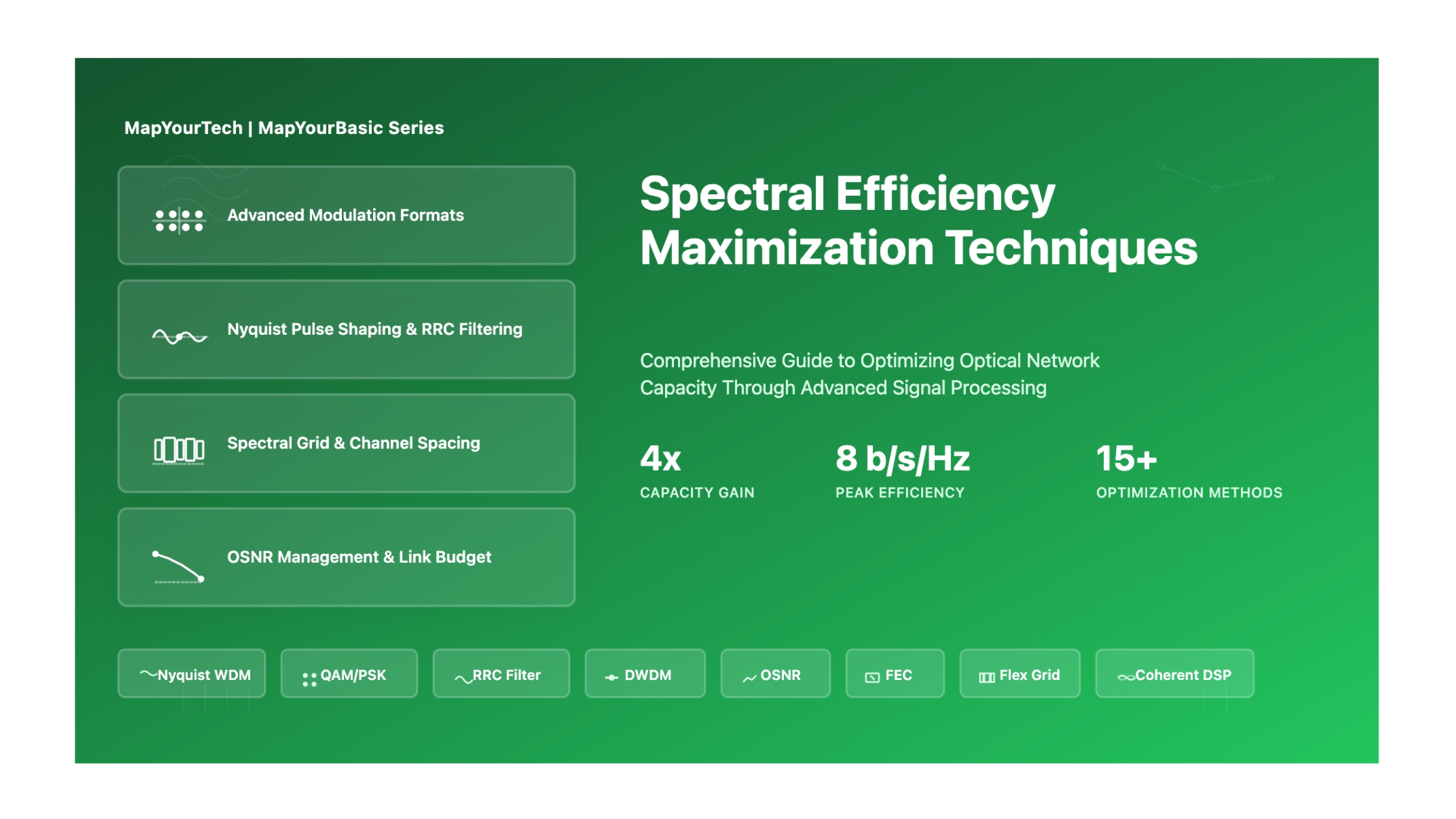
Spectral Efficiency Maximization Techniques
Fundamentals & Core Concepts
What is Spectral Efficiency?
Definition: Spectral Efficiency (SE) is defined as the information capacity of a single channel (in bits per second) divided by the frequency spacing between the carriers of a WDM system. It represents how efficiently the available optical spectrum is utilized to transmit data.
• Rs = Symbol rate (Gbaud)
• M = Number of constellation points in modulation format
• Δf = Frequency spacing between WDM channels (GHz)
• r = FEC overhead (e.g., 0.07 for 7% overhead)
• SE = Spectral Efficiency (bits/s/Hz)
Why Does Spectral Efficiency Matter?
The total system capacity is obtained as the product between spectral efficiency and the available bandwidth. Maximization of SE plays a critical role in maximizing overall system capacity for several key reasons:
Higher spectral efficiency allows more data to be transmitted within the same optical bandwidth, directly increasing network capacity without requiring additional fiber infrastructure or spectral resources.
By transmitting more bits per symbol, operators reduce the cost per bit transmitted, minimizing the need for parallel fiber deployment and reducing overall capital expenditure (CAPEX) and operational expenditure (OPEX).
With the exponential growth in data traffic driven by cloud services, 5G backhaul, video streaming, and IoT applications, the available optical spectrum becomes increasingly scarce. Efficient utilization is paramount.
When Does Spectral Efficiency Maximization Matter?
Spectral efficiency optimization is critical in the following scenarios:
- Long-haul and submarine networks: Where fiber capacity is fixed and expensive to upgrade
- Metro and regional networks: Where traffic aggregation requires high capacity within limited spectrum
- Data center interconnects: Where ultra-high capacity (400G, 800G, 1.6T) is needed over short to medium distances
- 5G fronthaul/backhaul: Where massive bandwidth demands must be met with existing fiber infrastructure
- Fixed grid DWDM systems: Where channel spacing is predetermined (50 GHz or 100 GHz grids)
- Flex-grid systems: Where dynamic spectrum allocation enables optimal SE based on modulation format
Physical and Technical Origins
Spectral efficiency is fundamentally limited by:
Shannon-Hartley Theorem: The theoretical upper bound of channel capacity is determined by the relationship between signal-to-noise ratio (SNR) and bandwidth. Higher-order modulation formats approach this limit but require exponentially higher optical signal-to-noise ratio (OSNR).
• C = Channel capacity (bits/s)
• B = Bandwidth (Hz)
• SNR = Signal-to-noise ratio
This fundamental limit governs the maximum achievable spectral efficiency in any communication system.
Key physical phenomena affecting spectral efficiency include:
- Fiber nonlinearities: Self-phase modulation (SPM), cross-phase modulation (XPM), and four-wave mixing (FWM) limit maximum launch power and degrade signal quality
- Chromatic dispersion: Causes pulse spreading, limiting symbol rates and requiring compensation
- Polarization mode dispersion (PMD): Introduces signal distortion that must be compensated using DSP
- Amplifier noise: ASE noise from EDFAs degrades OSNR, limiting achievable modulation orders
- Laser linewidth: Phase noise from transmitter and local oscillator lasers affects higher-order modulation formats
Mathematical Framework
Core Mathematical Relationships
• Rs = Symbol rate (Gbaud)
• M = Modulation order (4 for QPSK, 16 for 16QAM, 64 for 64QAM)
• N = Number of polarizations (typically 2 for PDM)
• FEC_overhead = Forward error correction overhead (typically 0.07 to 0.25)
Example: For 32 Gbaud PDM-QPSK with 20% FEC overhead:
Data Rate = 32 × log₂(4) × 2 × (1 - 0.20) = 32 × 2 × 2 × 0.80 = 102.4 Gbps
• f = 1 (Δf = Rs): Ideal Nyquist-WDM - Maximum spectral efficiency
• f > 1 (Δf > Rs): Quasi-Nyquist-WDM - Practical implementation with guard bands
• f < 1 (Δf < Rs): Super-Nyquist-WDM - Overlapping spectra, requires advanced processing
Example: For 32 Gbaud with 32 GHz channel spacing:
f_normalized = 32 GHz / 32 Gbaud = 1.0 (Ideal Nyquist)
Modulation-specific OSNR penalties:
• PDM-QPSK (M=4): 0 dB (reference)
• PDM-8QAM (M=8): +2.0 dB
• PDM-16QAM (M=16): +4.0 dB
• PDM-32QAM (M=32): +6.0 dB
• PDM-64QAM (M=64): +8.5 dB
Example: For PDM-16QAM:
OSNR_required = 11 + 10 × log₁₀(16/4) = 11 + 6.02 ≈ 17 dB
This metric evaluates the overall performance of transmission systems, balancing capacity and reach.
Example: 2 b/s/Hz SE over 6000 km with 4 THz bandwidth:
CDP = 2 × 6000 × 4000 = 48,000,000 Gbps·km = 48 Pbps·km
Practical Calculation Example
Scenario: Design a 400G coherent system over 500 km
Step 1: Select modulation format
For 500 km reach, 16QAM is suitable (typical reach 400-800 km)
Step 2: Calculate required symbol rate
Target: 400 Gbps net rate
With 20% FEC overhead: Gross rate = 400 / 0.80 = 500 Gbps
For PDM-16QAM: Rs = 500 / (log₂(16) × 2) = 500 / 8 = 62.5 Gbaud
Step 3: Determine channel spacing
With 10% roll-off: Bandwidth = 62.5 × 1.10 = 68.75 GHz
Use 75 GHz channel spacing for guard band
Step 4: Calculate spectral efficiency
SE = 500 Gbps / 75 GHz = 6.67 bits/s/Hz
Step 5: Verify OSNR budget
Required OSNR for 16QAM ≈ 17 dB
With 2 dB implementation penalty: Target OSNR = 19 dB
Verify link budget supports this OSNR level
Key Parameter Relationships
| Parameter | Formula | Units | Typical Range |
|---|---|---|---|
| Symbol Rate | Rs = Bit Rate / (log₂(M) × N) | Gbaud | 32-90 Gbaud |
| Spectral Width | BW = Rs × (1 + roll-off) | GHz | 35-100 GHz |
| Bits per Symbol | b = log₂(M) × N | bits/symbol | 2-12 bits |
| Net SE | SE_net = SE_gross × (1 - FEC_OH) | bits/s/Hz | 1-8 bits/s/Hz |
| Required OSNR | Function of M and distance | dB (0.1 nm) | 10-25 dB |
Types & Components of SE Maximization
Classification by Approach
1. Modulation Format Optimization
The choice of modulation format fundamentally determines spectral efficiency. Higher-order modulation formats encode more bits per symbol, increasing SE at the cost of requiring higher OSNR.
| Modulation Format | Bits/Symbol (with PDM) | Typical SE (bits/s/Hz) | OSNR Requirement | Typical Reach |
|---|---|---|---|---|
| PDM-BPSK | 2 | 1.5-2.0 | 9-10 dB | >4000 km |
| PDM-QPSK | 4 | 3.0-4.0 | 10-12 dB | 2000-4000 km |
| PDM-8QAM | 6 | 4.5-6.0 | 14-16 dB | 1000-2000 km |
| PDM-16QAM | 8 | 6.0-8.0 | 17-19 dB | 400-800 km |
| PDM-32QAM | 10 | 7.5-9.5 | 21-23 dB | 200-400 km |
| PDM-64QAM | 12 | 9.0-11.0 | 24-26 dB | 80-200 km |
Going from PDM-QPSK to PDM-16QAM doubles the data rate but reduces optical reach by approximately a factor of 5 due to the reduced minimum distance between constellation points and increased sensitivity to channel impairments.
2. Channel Spacing Optimization (Nyquist-WDM)
Reducing frequency spacing between WDM channels increases spectral efficiency. Nyquist-WDM techniques enable channel spacing approaching the symbol rate through precise spectral shaping.
Nyquist-WDM Categories:
- Ideal Nyquist-WDM (f = 1.0): Channel spacing equals symbol rate (Δf = Rs). Achieves maximum theoretical SE with rectangular spectral shaping and precise timing.
- Quasi-Nyquist-WDM (f = 1.05-1.2): Small guard band for practical implementation. Typical in commercial systems with 5-20% excess spacing over symbol rate.
- Super-Nyquist-WDM (f = 0.9-0.99): Overlapping spectra requiring advanced DSP to manage controlled inter-channel interference. Achieves highest SE but with increased complexity.
3. Polarization Division Multiplexing (PDM)
PDM doubles spectral efficiency by transmitting independent data streams on two orthogonal polarization states of light without additional bandwidth.
4. Advanced Coding Techniques
Forward Error Correction (FEC) and advanced coding schemes enable operation at lower OSNR, allowing higher-order modulation formats or extended reach.
| FEC Type | Overhead | Net Coding Gain | Pre-FEC BER Threshold | Application |
|---|---|---|---|---|
| Standard FEC (RS) | 7% | 5-6 dB | ~10⁻³ | Legacy systems |
| Enhanced FEC | 15% | 8-9 dB | ~10⁻² | 100G systems |
| Soft-Decision FEC | 20-25% | 11-13 dB | 1-2×10⁻² | 400G/800G coherent |
5. Orthogonal Frequency Division Multiplexing (OFDM)
CO-OFDM divides a high-speed channel into multiple closely-spaced orthogonal subcarriers, each modulated independently.
- Orthogonality: Subcarriers can overlap without interference when guard-band spacing equals subcarrier spacing multiples
- Flexible access: Individual subcarriers can be accessed independently for routing or drop/add
- Dispersion resilience: Lower symbol rate per subcarrier reduces sensitivity to chromatic dispersion
- Adaptive modulation: Different subcarriers can use different modulation orders based on channel conditions
6. Probabilistic Constellation Shaping (PCS)
PCS optimizes spectral efficiency by using a non-uniform distribution of constellation points, with more frequent use of lower-amplitude symbols.
PCS Benefits:
- Achieves Gaussian-like amplitude distribution approaching Shannon limit
- Provides 0.5-1.5 dB OSNR gain compared to conventional uniform QAM
- Enables flexible rate adaptation by varying shaping strength
- Optimizes reach-capacity trade-off without changing modulation hardware
Component Breakdown
Transmitter Components
- Narrow-linewidth laser: Linewidth <100 kHz for high-order modulation (ECL or integrated tunable laser)
- Digital signal processor (DSP): Pre-distortion, pulse shaping, modulation mapping
- DAC: High-speed digital-to-analog conversion (>80 GSa/s for 64 Gbaud)
- IQ modulator: Dual-polarization IQ modulator for independent I/Q and X/Y polarization control
- Optical multiplexer: Combines WDM channels with precise wavelength control
Receiver Components
- Local oscillator (LO): Narrow-linewidth laser for coherent detection
- Polarization-diversity optical hybrid: 90° hybrid for I/Q demodulation on both polarizations
- Balanced photodetectors: High-bandwidth photodiodes (>70 GHz for 64 Gbaud)
- ADC: High-speed analog-to-digital conversion with sufficient resolution (6-8 bits)
- DSP: Chromatic dispersion compensation, PMD compensation, carrier recovery, equalization, FEC decoding
Network Components
- Flex-grid ROADMs: Variable channel spacing for adaptive spectral allocation
- Waveform-controlled transponders: Precise spectral shaping for Nyquist operation
- Distributed amplification: Raman amplifiers for improved OSNR and nonlinearity management
- Advanced fiber: Large effective area (>100 μm²) for reduced nonlinearities
Effects & Impacts
System-Level Effects
1. OSNR Requirements and Link Budget
Higher spectral efficiency through advanced modulation formats dramatically increases OSNR requirements, directly impacting achievable transmission distance and system margin.
Quantitative OSNR Impact: Moving from PDM-QPSK (4 bits/symbol) to PDM-64QAM (12 bits/symbol) requires approximately 14 dB additional OSNR - equivalent to reducing allowable span loss by 14 dB or halving the number of spans without regeneration.
| Modulation | Required OSNR @ 10⁻³ BER | OSNR Penalty vs QPSK | Max Spans (80km, 0.2dB/km) | Impact Level |
|---|---|---|---|---|
| PDM-QPSK | 11 dB | 0 dB | 25-30 spans | Reference |
| PDM-8QAM | 15 dB | +4 dB | 15-18 spans | Moderate |
| PDM-16QAM | 19 dB | +8 dB | 8-10 spans | High |
| PDM-32QAM | 23 dB | +12 dB | 4-5 spans | Severe |
| PDM-64QAM | 25 dB | +14 dB | 2-3 spans | Critical |
2. Nonlinear Impairment Sensitivity
Higher-order modulation formats have reduced Euclidean distance between constellation points, making them more susceptible to nonlinear distortions.
Self-Phase Modulation (SPM): Signal-dependent phase noise increases with constellation density. 64QAM tolerates only ~1 radian nonlinear phase shift vs. ~3 radians for QPSK.
Cross-Phase Modulation (XPM): Inter-channel interference becomes critical in dense WDM systems. Required channel spacing increases 2-3x for 64QAM vs. QPSK.
Four-Wave Mixing (FWM): Generates spurious frequencies that may overlap signal channels in Nyquist-WDM systems with tight channel spacing.
3. Dispersion Tolerance
Higher symbol rates (increased baud rate) require stronger dispersion compensation and reduce tolerance to uncompensated chromatic dispersion.
4. Phase Noise Sensitivity
Higher-order modulation formats require significantly narrower laser linewidths due to reduced phase margin.
| Modulation | Phase Margin | Required Linewidth | Linewidth Tolerance |
|---|---|---|---|
| QPSK | 45° | <500 kHz | Relaxed |
| 8QAM | 22.5° | <200 kHz | Moderate |
| 16QAM | 16.9° | <100 kHz | Stringent |
| 32QAM | 10.9° | <50 kHz | Very Stringent |
| 64QAM | 7.7° | <30 kHz | Critical |
Performance Implications
Reach vs. Capacity Trade-off
Fundamental Trade-off: Every doubling of spectral efficiency through higher modulation order typically reduces transmission reach by 60-80% due to OSNR requirements and nonlinearity sensitivity.
Example: A 100G PDM-QPSK system with 4000 km reach would achieve only 800-1000 km reach when upgraded to 200G PDM-16QAM for doubled capacity.
Cost-Performance Analysis
- Cost per bit decreases with higher SE in short to medium reach applications (< 500 km)
- Transponder cost increases with DSP complexity (64 Gbaud DSP costs ~2x more than 32 Gbaud)
- System complexity increases requiring more sophisticated management, monitoring, and control
- Power consumption scales with DSP complexity: 400G coherent typically consumes 15-25W vs. 8-12W for 100G
Tolerance Levels and Thresholds
| Impairment | QPSK Tolerance | 16QAM Tolerance | 64QAM Tolerance | Mitigation Required |
|---|---|---|---|---|
| CD (ps/nm) | >100,000 | >50,000 | >20,000 | DSP compensation |
| PMD (ps) | >50 | >30 | >15 | Adaptive equalization |
| PDL (dB) | >3 | >2 | >1.5 | Component selection |
| Nonlinear Phase (rad) | >2.5 | >1.5 | >0.8 | Power optimization |
| Laser Linewidth (kHz) | <500 | <100 | <30 | ECL/integrated lasers |
Mitigation Strategies Overview
- Adaptive modulation: Dynamically select modulation format based on link conditions and OSNR
- Distributed amplification: Raman amplification reduces noise figure and improves OSNR budget
- Advanced DSP: Nonlinearity compensation algorithms (DBP, perturbation-based methods)
- Optimized fiber: Large effective area fibers (LEAF) with Aeff > 100 μm² reduce nonlinear coefficient
- Power management: Optimal launch power balancing OSNR and nonlinearity
- Flex-grid networks: Dynamic bandwidth allocation matching format requirements
Techniques & Solutions
1. Nyquist Pulse Shaping Technique
Objective: Achieve rectangular spectrum shape to minimize channel spacing while eliminating inter-symbol interference (ISI).
Method:
- Apply root-raised-cosine (RRC) filtering at transmitter and receiver
- Digital pulse shaping in DSP before DAC
- Optimize roll-off factor (α = 0.01-0.2) for spectral compactness
- Precise timing recovery to maintain orthogonality
• Rs = Symbol rate (Gbaud)
• α = Roll-off factor (0 for ideal, 0.01-0.2 for practical)
• BW = Occupied bandwidth (GHz)
Example: 32 Gbaud with α = 0.1:
BW = 32 × 1.1 = 35.2 GHz (can fit in 37.5 or 50 GHz grid)
Advantages and Disadvantages
| Advantages | Disadvantages |
|---|---|
| Achieves channel spacing ≈ symbol rate | Requires precise DSP and timing synchronization |
| Maximizes spectral efficiency (SE ≈ bits/symbol) | Sensitive to frequency offset and jitter |
| Eliminates ISI with proper filtering | Increased DAC/ADC bandwidth requirements |
| Compatible with flex-grid ROADMs | Higher DSP complexity and power consumption |
2. Coherent Detection with Digital Signal Processing
Purpose: Coherent detection with DSP enables linear recovery of both in-phase (I) and quadrature (Q) components, allowing use of advanced modulation formats and compensation of transmission impairments.
Key DSP Functions:
- Chromatic Dispersion Compensation: Digital equalization of accumulated dispersion (up to 100,000 ps/nm)
- Polarization Demultiplexing: Separates PDM signal streams using adaptive equalizers (CMA, RDE)
- PMD Compensation: Adaptive equalization for time-varying polarization effects
- Carrier Recovery: Phase estimation and correction using Viterbi-Viterbi or blind phase search
- Frequency Offset Compensation: Corrects for transmitter-LO frequency mismatch
- Nonlinearity Compensation: Digital backpropagation or perturbation-based methods
- Use narrow-linewidth ECL lasers (<100 kHz) for transmitter and LO
- Implement 2x oversampling for optimal DSP performance
- ADC resolution: 6-8 bits for soft-decision FEC compatibility
- Adaptive equalization with 50-200 taps for PMD and channel distortion
- Frequency offset estimation range: ±2-5 GHz
3. Polarization Division Multiplexing (PDM)
Implementation Steps:
- Transmitter: Split signal into X and Y polarizations using polarization beam splitter (PBS)
- Modulation: Independently modulate each polarization with separate data streams
- Combining: Combine orthogonal polarizations using polarization beam combiner (PBC)
- Receiver: Polarization-diversity coherent receiver with 4 balanced detectors
- Demultiplexing: Digital polarization demultiplexing using adaptive MIMO equalizer
Real-World Application: All modern 100G, 200G, 400G, and 800G coherent systems utilize PDM as a standard technique. A 100G PDM-QPSK system transmits 50 Gbps on each polarization at 25 Gbaud per polarization.
4. Advanced Modulation Format Selection
| Application | Distance | Recommended Format | Rationale |
|---|---|---|---|
| Submarine/Ultra Long-Haul | >2000 km | PDM-BPSK or PDM-QPSK | Maximum reach, lowest OSNR requirement |
| Long-Haul Terrestrial | 800-2000 km | PDM-QPSK or PDM-8QAM | Balance of reach and capacity |
| Regional/Metro | 200-800 km | PDM-16QAM | High capacity with acceptable reach |
| Metro Core | 80-200 km | PDM-32QAM or PDM-64QAM | Maximum spectral efficiency |
| Data Center Interconnect | <80 km | PDM-64QAM with PCS | Ultra-high capacity, short reach |
5. Probabilistic Constellation Shaping (PCS)
Principle: PCS modifies the probability distribution of transmitted symbols to approximate a Gaussian distribution, approaching the Shannon limit more closely than uniform QAM.
Implementation:
- Apply distribution matching algorithm to input bits before modulation mapping
- Inner constellation points used more frequently than outer points
- Maintain constant average power while varying entropy
- Achieves 0.5-1.5 dB shaping gain in OSNR
Applications:
- Flexible rate adaptation without changing hardware
- Optimization of reach-capacity trade-off
- Improved performance in OSNR-limited scenarios
- Standard feature in 400G and 800G transponders
Comparison of Techniques
| Technique | SE Improvement | Complexity | Cost Impact | Maturity |
|---|---|---|---|---|
| PDM | 2x | Medium | Low | Mature |
| Nyquist Shaping | 20-40% | Medium | Low | Mature |
| Higher-Order QAM | 2-3x | High | Medium | Mature |
| PCS | 10-15% | Medium | Low | Emerging |
| Super-Channels | 15-25% | High | Medium | Mature |
Design Guidelines & Methodology
Step-by-Step Design Process
- Define capacity requirements: Target bit rate per wavelength (100G, 200G, 400G, 800G)
- Determine transmission distance: Maximum unamplified span length and total distance
- Identify fiber type: SSMF, NZDSF, LEAF, or specialty fiber
- Specify OSNR budget: Available OSNR based on amplifier configuration
- Define grid type: Fixed grid (50 GHz, 100 GHz) or flex-grid
- Establish constraints: Power consumption, cost, latency, redundancy
Decision Framework:
ELSE IF Distance > 800 km → PDM-QPSK or PDM-8QAM
ELSE IF Distance > 200 km → PDM-16QAM
ELSE → PDM-32QAM or PDM-64QAM
1. Calculate required OSNR for selected format
2. Compare with available OSNR budget
3. Add 3-4 dB system margin
4. If insufficient, select lower-order format or add amplification
Common Pitfalls to Avoid
| Pitfall | Consequence | Prevention |
|---|---|---|
| Insufficient OSNR margin | System fails under environmental variations | Always include 3-5 dB margin in budget |
| Excessive launch power | Nonlinear distortion degrades performance | Optimize per modulation format guidelines |
| Inadequate FEC overhead | Unable to correct errors in marginal conditions | Use 20-25% OH for long-haul, >15 dB gain |
| Laser linewidth too wide | Phase noise degrades higher-order formats | Verify <100 kHz for 16QAM, <30 kHz for 64QAM |
| Mismatched channel spacing | Spectral overlap or wasted spectrum | Account for roll-off factor and guard bands |
Pre-Deployment Checklist:
- Modulation format matches distance and OSNR budget
- Symbol rate achievable with available DSP/DAC/ADC technology
- Channel spacing compatible with ROADM grid
- FEC overhead provides sufficient coding gain for target BER
- Laser linewidth meets requirements for selected modulation
- Launch power optimized for nonlinearity and OSNR balance
- System margin adequate for aging and temperature variations (3-5 dB)
- PMD budget within transponder equalization capability
- Spectral efficiency target achieved
Interactive Simulators
Explore spectral efficiency concepts through four interactive real-time simulators. All calculations update automatically as you adjust the sliders.
| Format | Capacity (Gbps) | Required OSNR (dB) | Status |
|---|
Optimization Recommendation:
Practical Applications & Case Studies
Real-World Deployment Scenarios
Challenge: Maximize capacity while maintaining ultra-long reach over legacy SSMF infrastructure
Solution:
- Modulation: PDM-QPSK for optimal reach-capacity balance
- Symbol Rate: 31.25 Gbaud with 5% roll-off
- Channel Spacing: 50 GHz fixed grid (SE = 2.0 bits/s/Hz)
- Amplification: Hybrid EDFA with distributed Raman (2nd order)
Results:
- Total Capacity: 80 channels × 100 Gbps = 8 Tbps in C-band
- Achieved OSNR: 13-15 dB end-of-line (3-5 dB margin)
- System Availability: 99.999% with protection switching
- Cost Savings: 40% reduction vs. deploying new fiber routes
Challenge: Maximize spectral efficiency for capacity growth in constrained metro spectrum
Solution:
- Modulation: PDM-16QAM with adaptive configuration
- Symbol Rate: 62.5 Gbaud with 10% roll-off
- Channel Spacing: 75 GHz flex-grid (SE = 5.33 bits/s/Hz)
- Network: Flex-grid ROADMs with 12.5 GHz granularity
Results:
- Total Capacity: 40 channels × 400 Gbps = 16 Tbps
- Spectrum Utilization: 3 THz (C-band fully loaded)
- Power Efficiency: 2.5 W per 100G equivalent
- Flexibility: Adaptive modulation enables 200-600 km reach variation
Challenge: Maximize capacity with minimal footprint and power consumption
Solution:
- Modulation: PDM-64QAM with probabilistic constellation shaping
- Symbol Rate: 90 Gbaud with 12% roll-off
- Architecture: 2 × 400G subcarriers in super-channel configuration
- Channel Spacing: 112.5 GHz per super-channel (SE = 7.1 bits/s/Hz)
Results:
- Single λ capacity: 800 Gbps per super-channel
- Rack Density: 19.2 Tbps per RU
- Power Efficiency: 20W per 800G (25 pJ/bit)
- Latency: <400 μs end-to-end including DSP
- Cost per Bit: 60% reduction vs. 400G deployment
Troubleshooting Guide
| Symptom | Probable Cause | Solution |
|---|---|---|
| High BER on specific channels | Insufficient OSNR | Optimize launch power, verify amplifier operation, reduce span loss |
| Performance degrades over time | Component aging, fiber degradation | Clean/replace connectors, adjust amplifier pump power |
| Intermittent errors | PMD fluctuations, polarization issues | Verify DSP equalizer operation, check for mechanical stress on fiber |
| Cannot achieve target SE | Modulation format too aggressive for link | Select lower-order modulation, improve OSNR through Raman amplification |
| Nonlinear penalties observed | Excessive launch power | Reduce launch power, verify power equalization, implement nonlinearity compensation |
Quick Reference: Modulation Format Selection
| Format | Bits/Symbol | Required OSNR | Typical Reach | Best Use Case |
|---|---|---|---|---|
| PDM-BPSK | 2 | 9-10 dB | >4000 km | Submarine, ultra-long haul |
| PDM-QPSK | 4 | 11-13 dB | 2000-4000 km | Long-haul terrestrial |
| PDM-8QAM | 6 | 15-17 dB | 1000-2000 km | Regional networks |
| PDM-16QAM | 8 | 18-20 dB | 400-800 km | Metro/regional |
| PDM-32QAM | 10 | 22-24 dB | 200-400 km | Metro core |
| PDM-64QAM | 12 | 25-27 dB | <200 km | Data center interconnect |
- Spectral efficiency directly determines network capacity utilization and is defined as bits/s per Hz of spectrum
- Higher-order modulation formats (16QAM, 64QAM) increase SE but require exponentially higher OSNR and reduce reach
- Nyquist-WDM pulse shaping enables channel spacing approaching symbol rate, maximizing SE with minimal inter-symbol interference
- Polarization division multiplexing (PDM) doubles SE without additional spectrum or OSNR penalty
- Coherent detection with DSP enables compensation of linear impairments and supports advanced modulation formats
- Fundamental trade-off exists between capacity (SE), reach (distance), and cost - optimization depends on application
- Probabilistic constellation shaping provides 0.5-1.5 dB OSNR gain approaching Shannon limit
- Modern 400G systems achieve 6-8 bits/s/Hz SE using PDM-16QAM with Nyquist shaping over metro distances
- OSNR budget planning must account for amplifier noise figure, span count, nonlinear penalties, and aging margin
- Adaptive modulation enables flexible networks optimizing SE based on real-time link conditions and distance
Note: This guide is based on industry standards, best practices, and real-world implementation experiences. Specific implementations may vary based on equipment vendors, network topology, and regulatory requirements. Always consult with qualified network engineers and follow vendor documentation for actual deployments.
Unlock Premium Content
Join over 400K+ optical network professionals worldwide. Access premium courses, advanced engineering tools, and exclusive industry insights.
Already have an account? Log in here