
Generic selectors
Exact matches only
Search in title
Search in content
Post Type Selectors
Articles
lp_course
lp_lesson
Back
HomeFundamentalsStimulated Raman Scattering (SRS) Interaction in C and L Band Optical Networks
Stimulated Raman Scattering (SRS) Interaction in C and L Band Optical Networks

Stimulated Raman Scattering (SRS) Interaction in C and L Band Optical Networks

Last Updated: April 2, 2026
1 min read
112
SRS Interaction in C and L Band Optical Networks - Part 1

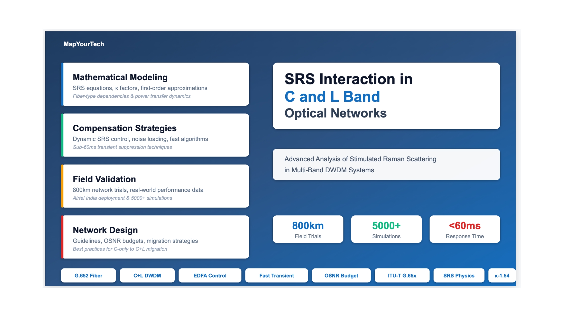
Stimulated Raman Scattering (SRS) Interaction in C and L Band Optical Networks

A Comprehensive Technical Analysis of SRS Effects, Compensation Strategies, and Field Trial Results in C+L Band DWDM Systems

1. Executive Summary & Key Takeaways

Stimulated Raman Scattering (SRS) creates significant power redistribution between C-band and L-band channels in dual-band optical networks. When both bands operate simultaneously, optical power transfers from shorter wavelengths (C-band) to longer wavelengths (L-band), resulting in:

  • C-Band: Additional loss of 0.6-1.4 dB per span and spectral tilt requiring compensation
  • L-Band: Gain from C-band with corresponding tilt effects
  • Transients: Band failures cause rapid power changes (5+ dB) within milliseconds, risking traffic disruption

Critical Findings from 5000+ Simulations and Field Trials

Aspect Key Finding Impact Level Mitigation Required
SRS Loss (C-Band) 0.6-1.4 dB per span at full load HIGH EDFA gain adjustment
SRS Tilt (C-Band) Up to 5 dB across C-band spectrum MEDIUM Dynamic gain equalization
Transient Response 5+ dB power surge in <10 ms CRITICAL Fast SRS compensation (<60 ms)
Fiber Type Variation 54% difference (G.652 vs G.656) MEDIUM Fiber-specific κ factors
Channel Distribution Non-uniform loading increases SRS LOW-MED Distribution-aware algorithms

Three Approaches to SRS Management

Approach 1: Dynamic SRS Compensation

Method: Real-time power monitoring and fast gain adjustment

Response Time: <60 milliseconds

Advantage: No additional hardware required

Trade-off: Batch processing for multiple wavelengths

Approach 2: Noise Loading

Method: Inject ASE noise into unused channels

Response Time: Static (no transients)

Advantage: Predictable, continuous equalization

Trade-off: Requires dual noise loader hardware

Approach 3: Hybrid Strategy

Method: Pre-emphasis + fast compensation

Response Time: <30 milliseconds

Advantage: Optimal performance & resilience

Trade-off: Increased system complexity

Critical Design Consideration: Traditional gain control methods (seconds-scale response) are inadequate for managing SRS-induced transients. A band failure can cause 5+ dB power increase in surviving channels within milliseconds, potentially causing traffic hits if not compensated rapidly.

2. Introduction to SRS in Optical Networks

2.1 Physical Mechanism of Stimulated Raman Scattering

Stimulated Raman Scattering is an inelastic nonlinear optical effect that occurs when light propagates through optical fiber. Unlike elastic effects (such as Four-Wave Mixing or Cross-Phase Modulation) where photons maintain their energy, SRS involves actual energy transfer between optical channels through interaction with molecular vibrations in the silica fiber.

The fundamental physics can be understood through the following mechanism:

  1. Photon-Phonon Interaction: High-energy photons from shorter wavelength channels (C-band, ~1530-1565 nm) interact with silica molecular vibrations (phonons) in the optical fiber.
  2. Energy Transfer: The incident photon loses a quantum of energy to create a phonon, producing a new photon at a longer wavelength (L-band, ~1570-1610 nm) with lower energy.
  3. Stimulated Process: The presence of L-band photons stimulates this process, making it dramatically more efficient than spontaneous Raman scattering.
  4. Frequency Shift: The Raman gain peak occurs approximately 13.2 THz (~100 nm) below the pump wavelength, which perfectly overlaps the frequency separation between C-band and L-band.

Figure 1: SRS Energy Transfer Mechanism in C+L Band Systems

Optical Fiber C-Band 1530-1565nm L-Band 1570-1610nm SRS Interaction Energy Transfer C-Band ↓ Power Loss L-Band ↑ Power Gain Power transfers from C-band (blue) to L-band (red) via molecular vibrations

2.2 Why SRS Matters in C+L Band Systems

The significance of SRS in dual-band optical networks stems from several critical factors that distinguish it from single-band operation:

2.2.1 Capacity Expansion Drivers

Operators face unprecedented bandwidth demands driven by cloud computing, 8K video streaming, IoT proliferation, and 5G backhaul requirements. When C-band spectrum (approximately 4.8 THz of bandwidth) reaches full utilization, three options exist:

Solution Capacity Increase CAPEX Impact Implementation Time SRS Consideration
Deploy New Fiber 2x (new C-band) Very High 6-24 months None (separate fiber)
Add L-Band 2x (C+L bands) Low-Medium 1-3 months Critical (manage SRS)
Higher Baud Rates 1.2-1.5x Medium Immediate Minimal

2.2.2 Magnitude of SRS Effects

Figure 2: SRS Loss per Span vs. Total Optical Power

Key Observation: At full C+L loading with 96 channels (48 per band) at +3 dBm per channel launch power, each 80km G.652.D fiber span experiences approximately 1.2 dB of additional C-band loss due to SRS. Over a 10-span system, this accumulates to 12 dB of extra loss requiring compensation.

3. Mathematical Foundation of SRS Interaction

3.1 Fundamental Differential Equation

The evolution of optical power for any channel as it propagates through fiber in the presence of SRS is governed by a system of coupled differential equations. For a channel at frequency i in a system with N total channels across C+L bands, the power evolution is:

dPi/dz = -αiPi - Σj=i+1N gi,jPiPj + Σk=1i-1 gk,iPiPk    (Eq. 1)

Where:
  Pi       = Optical power of i-th channel [mW]
  z         = Distance along fiber [km]
  αi       = Fiber attenuation coefficient for i-th channel [km-1]
  gi,j     = Raman gain coefficient between channels i and j [W-1km-1]
  N         = Total number of channels in C+L band system

Three Terms Represent:
  Term 1:   Wavelength-dependent loss (WDL) due to fiber attenuation
  Term 2:   Power loss due to SRS from channel i to longer wavelength channels (j>i)
  Term 3:   Power gain due to SRS from shorter wavelength channels (k<i) to channel i
Premium Article — Free 23% Preview

Read the Full Analysis with Premium

The remaining 77% of this article — the design numbers, trade-offs and field guidance — is part of MapYourTech Premium, along with the full premium library, courses and professional tools.

Instant access · Cancel anytime · 48-hour trial available
Sanjay Yadav

Optical Communications & Network Automation Expert | Author of 3 Books for Optical Engineers | Founder, MapYourTech

Optical networking engineer with nearly two decades of experience across DWDM, OTN, coherent optics, submarine systems, and cloud infrastructure. Founder of MapYourTech.

Follow on LinkedIn
Share:

You May Also Like

15 min read 6 0 Like Connector Types and Their Loss Budgets: SC, LC, MPO Skip to main content MapYourTech...
  • Free
  • July 11, 2026
16 min read 6 0 Like Cooled vs Uncooled Lasers: The Pluggable Power Trade-off Skip to main content MapYourTech |...
  • Free
  • July 11, 2026
16 min read 7 0 Like Automation Blast Radius: Scoping What a Bad Intent Can Touch Skip to main content...
  • Free
  • July 11, 2026

Course Title

Course description and key highlights

Course Content

Course Details


