Animated CTA Banner
MapYourTech
MapYourTech has always been about YOUR tech journey, YOUR questions, YOUR thoughts, and most importantly, YOUR growth. It’s a space where we "Map YOUR Tech" experiences and empower YOUR ambitions.
To further enhance YOUR experience, we are working on delivering a professional, fully customized platform tailored to YOUR needs and expectations.
Thank you for the love and support over the years. It has always motivated us to write more, share practical industry insights, and bring content that empowers and inspires YOU to excel in YOUR career.
We truly believe in our tagline:
“Share, explore, and inspire with the tech inside YOU!”
Let us know what YOU would like to see next! Share YOUR thoughts and help us deliver content that matters most to YOU.
Share YOUR Feedback
Tag

Optical networks

Browsing

RESTCONF (RESTful Configuration Protocol) is a network management protocol designed to provide a simplified, REST-based interface for managing network devices using HTTP methods. RESTCONF builds on the capabilities of NETCONF by making network device configuration and operational data accessible over the ubiquitous HTTP/HTTPS protocol, allowing for easy integration with web-based tools and services. It leverages the YANG data modeling language to represent configuration and operational data, providing a modern, API-driven approach to managing network infrastructure. Lets explore the fundamentals of RESTCONF, its architecture, how it compares with NETCONF, the use cases it serves, and the benefits and drawbacks of adopting it in your network.

What Is RESTCONF?

RESTCONF (Representational State Transfer  Configuration) is defined in RFC 8040 and provides a RESTful API that enables network operators to access, configure, and manage network devices using HTTP methods such as GET, POST, PUT, PATCH, and DELETE. Unlike NETCONF, which uses a more complex XML-based communication, RESTCONF adopts a simple REST architecture, making it easier to work with in web-based environments and for integration with modern network automation tools.

Key Features:

  • HTTP-based: RESTCONF is built on the widely-adopted HTTP/HTTPS protocols, making it compatible with web services and modern applications.
  • Data Model Driven: Similar to NETCONF, RESTCONF uses YANG data models to define how configuration and operational data are structured.
  • JSON/XML Support: RESTCONF allows the exchange of data in both JSON and XML formats, giving it flexibility in how data is represented and consumed.
  • Resource-Based: RESTCONF treats network device configurations and operational data as resources, allowing them to be easily manipulated using HTTP methods.

How RESTCONF Works

RESTCONF operates as a client-server model, where the RESTCONF client (typically a web application or automation tool) communicates with a RESTCONF server (a network device) using HTTP. The protocol leverages HTTP methods to interact with the data represented by YANG models.

HTTP Methods in RESTCONF:

  • GET: Retrieve configuration or operational data from the device.
  • POST: Create new configuration data on the device.
  • PUT: Update existing configuration data.
  • PATCH: Modify part of the existing configuration.
  • DELETE: Remove configuration data from the device.

RESTCONF provides access to various network data through a well-defined URI structure, where each part of the network’s configuration or operational data is treated as a unique resource. This resource-centric model allows for easy manipulation and retrieval of network data.

RESTCONF URI Structure and Example

RESTCONF URIs provide access to different parts of a device’s configuration or operational data. The general structure of a RESTCONF URI is as follows:

/restconf/<resource-type>/<data-store>/<module>/<container>/<leaf>
  • resource-type: Defines whether you are accessing data (/data) or operations (/operations).
  • data-store: The datastore being accessed (e.g., /running or /candidate).
  • module: The YANG module that defines the data you are accessing.
  • container: The container (group of related data) within the module.
  • leaf: The specific data element being retrieved or modified.

Example: If you want to retrieve the current configuration of interfaces on a network device, the RESTCONF URI might look like this:

GET /restconf/data/ietf-interfaces:interfaces

This request retrieves all the interfaces on the device, as defined in the ietf-interfaces YANG model.

RESTCONF Data Formats

RESTCONF supports two primary data formats for representing configuration and operational data:

  • JSON (JavaScript Object Notation): A lightweight, human-readable data format that is widely used in web applications and REST APIs.
  • XML (Extensible Markup Language): A more verbose, structured data format commonly used in network management systems.

Most modern implementations prefer JSON due to its simplicity and efficiency, particularly in web-based environments.

RESTCONF and YANG

Like NETCONF, RESTCONF relies on YANG models to define the structure and hierarchy of configuration and operational data. Each network device’s configuration is represented using a specific YANG model, which RESTCONF interacts with using HTTP methods. The combination of RESTCONF and YANG provides a standardized, programmable interface for managing network devices.

Example YANG Model Structure in JSON:

{
"ietf-interfaces:interface": {
"name": "GigabitEthernet0/1",
"description": "Uplink Interface",
"type": "iana-if-type:ethernetCsmacd",
"enabled": true
}
}

This JSON example represents a network interface configuration based on the ietf-interfaces YANG model.

Security in RESTCONF

RESTCONF leverages the underlying HTTPS (SSL/TLS) for secure communication between the client and server. It supports basic authentication, OAuth, or client certificates for verifying user identity and controlling access. This level of security is similar to what you would expect from any RESTful API that operates over the web, ensuring confidentiality, integrity, and authentication in the network management process.

Advantages of RESTCONF

RESTCONF offers several distinct advantages, especially in modern networks that require integration with web-based tools and automation platforms:

  • RESTful Simplicity: RESTCONF adopts a well-known RESTful architecture, making it easier to integrate with modern web services and automation tools.
  • Programmability: The use of REST APIs and data formats like JSON allows for easier automation and programmability, particularly in environments that use DevOps practices and CI/CD pipelines.
  • Wide Tool Support: Since RESTCONF is HTTP-based, it is compatible with a wide range of development and monitoring tools, including Postman, curl, and programming libraries in languages like Python and JavaScript.
  • Standardized Data Models: The use of YANG ensures that RESTCONF provides a vendor-neutral way to interact with devices, facilitating interoperability between devices from different vendors.
  • Efficiency: RESTCONF’s ability to handle structured data using lightweight JSON makes it more efficient than XML-based alternatives in web-scale environments.

Disadvantages of RESTCONF

While RESTCONF brings many advantages, it also has some limitations:

  • Limited to Configuration and Operational Data: RESTCONF is primarily used for retrieving and modifying configuration and operational data. It lacks some of the more advanced management capabilities (like locking configuration datastores) that NETCONF provides.
  • Stateless Nature: RESTCONF is stateless, meaning each request is independent. While this aligns with REST principles, it lacks the transactional capabilities of NETCONF’s stateful configuration model, which can perform commits and rollbacks in a more structured way.
  • Less Mature in Networking: NETCONF has been around longer and is more widely adopted in large-scale enterprise networking environments, whereas RESTCONF is still gaining ground.

When to Use RESTCONF

RESTCONF is ideal for environments that prioritize simplicity, programmability, and integration with modern web tools. Common use cases include:

  • Network Automation: RESTCONF fits naturally into network automation platforms, making it a good choice for managing dynamic networks using automation frameworks like Ansible, Terraform, or custom Python scripts.
  • DevOps/NetOps Integration: Since RESTCONF uses HTTP and JSON, it can easily be integrated into DevOps pipelines and tools such as Jenkins, GitLab, and CI/CD workflows, enabling Infrastructure as Code (IaC) approaches.
  • Cloud and Web-Scale Environments: RESTCONF is well-suited for managing cloud-based networking infrastructure due to its web-friendly architecture and support for modern data formats.

RESTCONF vs. NETCONF: A Quick Comparison

RESTCONF Implementation Steps

To implement RESTCONF, follow these general steps:

Step 1: Enable RESTCONF on Devices

Ensure your devices support RESTCONF and enable it. For example, on Cisco IOS XE, you can enable RESTCONF with:


restconf

Step 2: Send RESTCONF Requests

Once RESTCONF is enabled, you can interact with the device using curl or tools like Postman. For example, to retrieve the configuration of interfaces, you can use:

curl -k -u admin:admin "https://192.168.1.1:443/restconf/data/ietf-interfaces:interfaces"

Step 3: Parse JSON/XML Responses

RESTCONF responses will return data in JSON or XML format. If you’re using automation scripts (e.g., Python), you can parse this data to retrieve or modify configurations.

Summary

RESTCONF is a powerful, lightweight, and flexible protocol for managing network devices in a programmable way. Its use of HTTP/HTTPS, JSON, and YANG makes it a natural fit for web-based network automation tools and DevOps environments. While it lacks the transactional features of NETCONF, its simplicity and compatibility with modern APIs make it ideal for managing cloud-based and automated networks.

Simple Network Management Protocol (SNMP) is one of the most widely used protocols for managing and monitoring network devices in IT environments. It allows network administrators to collect information, monitor device performance, and control devices remotely. SNMP plays a crucial role in the health, stability, and efficiency of a network, especially in large-scale or complex infrastructures. Let’s explore the ins and outs of SNMP, its various versions, key components, practical implementation, and how to leverage it effectively depending on network scale, complexity, and device type.

What Is SNMP?

SNMP stands for Simple Network Management Protocol, a standardized protocol used for managing and monitoring devices on IP networks. SNMP enables network devices such as routers, switches, servers, printers, and other hardware to communicate information about their state, performance, and errors to a centralized management system (SNMP manager).

Key Points:

  • SNMP is an application layer protocol that operates on port 161 (UDP) for SNMP agent queries and port 162 (UDP) for SNMP traps.
  • It is designed to simplify the process of gathering information from network devices and allows network administrators to perform remote management tasks, such as configuring devices, monitoring network performance, and troubleshooting issues.

How SNMP Works

SNMP consists of three main components:

  • SNMP Manager: The management system that queries devices and collects data. It can be a network management software or platform, such as SolarWinds, PRTG, or Nagios.
  • SNMP Agent: Software running on the managed device that responds to queries and sends traps (unsolicited alerts) to the SNMP manager.
  • Management Information Base (MIB): A database of information that defines what can be queried or monitored on a network device. MIBs contain Object Identifiers (OIDs), which represent specific device metrics or configuration parameters.

The interaction between these components follows a request-response model:

  1. The SNMP manager sends a GET request to the SNMP agent to retrieve specific information.
  2. The agent responds with a GET response, containing the requested data.
  3. The SNMP manager can also send SET requests to modify configuration settings on the device.
  4. The SNMP agent can autonomously send TRAPs (unsolicited alerts) to notify the SNMP manager of critical events like device failure or threshold breaches.

SNMP Versions and Variants

SNMP has evolved over time, with different versions addressing various challenges related to security, scalability, and efficiency. The main versions are:

SNMPv1 (Simple Network Management Protocol Version 1)

    • Introduction: The earliest version, released in the late 1980s, and still in use in smaller or legacy networks.
    • Features: Provides basic management functions, but lacks robust security. Data is sent in clear text, which makes it vulnerable to eavesdropping.
    • Use Case: Suitable for simple or isolated network environments where security is not a primary concern.

SNMPv2c (Community-Based SNMP Version 2)

    • Introduction: Introduced to address some performance and functionality limitations of SNMPv1.
    • Features: Improved efficiency with additional PDU types, such as GETBULK, which allows for the retrieval of large datasets in a single request. It still uses community strings (passwords) for security, which is minimal and lacks encryption.
    • Use Case: Useful in environments where scalability and performance are needed, but without the strict need for security.

SNMPv3 (Simple Network Management Protocol Version 3)

    • Introduction: Released to address security flaws in previous versions.
    • Features:
              • User-based Security Model (USM): Introduces authentication and encryption to ensure data integrity and confidentiality. Devices and administrators must authenticate using username/password, and messages can be encrypted using algorithms like AES or DES.
              • View-based Access Control Model (VACM): Provides fine-grained access control to determine what data a user or application can access or modify.
              • Security Levels: Three security levels: noAuthNoPriv, authNoPriv, and authPriv, offering varying degrees of security.
    • Use Case: Ideal for large enterprise networks or any environment where security is a concern. SNMPv3 is now the recommended standard for new implementations.

SNMP Over TLS and DTLS

  • Introduction: An emerging variant that uses Transport Layer Security (TLS) or Datagram Transport Layer Security (DTLS) to secure SNMP communication.
  • Features: Provides better security than SNMPv3 in some contexts by leveraging more robust transport layer encryption.
  • Use Case: Suitable for modern, security-conscious organizations where protecting management traffic is a priority.

SNMP Communication Example

Here’s a basic example of how SNMP operates in a typical network as a reference for readers:

Scenario: A network administrator wants to monitor the CPU usage of a optical device.

  • Step 1: The SNMP manager sends a GET request to the SNMP agent on the optical device to query its CPU usage. The request contains the OID corresponding to the CPU metric (e.g., .1.3.6.1.4.1.9.2.1.57 for Optical devices).
  • Step 2: The SNMP agent on the optical device retrieves the requested data from its MIB and responds with a GET response containing the CPU usage percentage.
  • Step 3: If the CPU usage exceeds a defined threshold, the SNMP agent can autonomously send a TRAP message to the SNMP manager, alerting the administrator of the high CPU usage.

SNMP Message Types

SNMP uses several message types, also known as Protocol Data Units (PDUs), to facilitate communication between the SNMP manager and the agent:

  • GET: Requests information from the SNMP agent.
  • GETNEXT: Retrieves the next value in a table or list.
  • SET: Modifies the value of a device parameter.
  • GETBULK: Retrieves large amounts of data in a single request (introduced in SNMPv2).
  • TRAP: A notification from the agent to the manager about significant events (e.g., device failure).
  • INFORM: Similar to a trap, but includes an acknowledgment mechanism to ensure delivery (introduced in SNMPv2).

SNMP MIBs and OIDs

The Management Information Base (MIB) is a structured database of information that defines what aspects of a device can be monitored or controlled. MIBs use a hierarchical structure defined by Object Identifiers (OIDs).

  • OIDs: OIDs are unique identifiers that represent individual metrics or device properties. They follow a dotted-decimal format and are structured hierarchically.
    • Example: The OID .1.3.6.1.2.1.1.5.0 refers to the system name of a device.

Advantages of SNMP

SNMP provides several advantages for managing network devices:

  • Simplicity: SNMP is easy to implement and use, especially for small to medium-sized networks.
  • Scalability: With the introduction of SNMPv2c and SNMPv3, the protocol can handle large-scale network infrastructures by using bulk operations and secure communications.
  • Automation: SNMP can automate the monitoring of thousands of devices, reducing the need for manual intervention.
  • Cross-vendor Support: SNMP is widely supported across networking hardware and software, making it compatible with devices from different vendors (e.g., Ribbon, Cisco, Ciena, Nokia, Juniper, Huawei).
  • Cost-Effective: Since SNMP is an open standard, it can be used without additional licensing costs, and many open-source SNMP management tools are available.

Disadvantages and Challenges

Despite its widespread use, SNMP has some limitations:

  • Security: Early versions (SNMPv1, SNMPv2c) lacked strong security features, making them vulnerable to attacks. Only SNMPv3 introduces robust authentication and encryption.
  • Complexity in Large Networks: In very large or complex networks, managing MIBs and OIDs can become cumbersome. Bulk data retrieval (GETBULK) helps, but can still introduce overhead.
  • Polling Overhead: SNMP polling can generate significant traffic in very large environments, especially when retrieving large amounts of data frequently.

When to Use SNMP

The choice of SNMP version and its usage depends on the scale, complexity, and security requirements of the network:

Small Networks

  • Use SNMPv1 or SNMPv2c if security is not a major concern and simplicity is valued. These versions are easy to configure and work well in isolated environments where data is collected over a trusted network.

Medium to Large Networks

  • Use SNMPv2c for better efficiency and performance, especially when monitoring a large number of devices. GETBULK allows efficient retrieval of large datasets, reducing polling overhead.
  • Implement SNMPv3 for environments where security is paramount. The encryption and authentication provided by SNMPv3 ensure that sensitive information (e.g., passwords, configuration changes) is protected from unauthorized access.

Highly Secure Networks

  • Use SNMPv3 or SNMP over TLS/DTLS in networks that require the highest level of security (e.g., financial services, government, healthcare). These environments benefit from robust encryption, authentication, and access control mechanisms provided by these variants.

Implementation Steps

Implementing SNMP in a network requires careful planning, especially when using SNMPv3:

Step 1: Device Configuration

  • Enable SNMP on devices: For each device (e.g., switch, router), enable the appropriate SNMP version and configure the SNMP agent.
    • For SNMPv1/v2c: Define a community string (password) to restrict access to SNMP data.
    • For SNMPv3: Configure users, set security levels, and enable encryption.

Step 2: SNMP Manager Setup

  • Install SNMP management software such as PRTG, Nagios, MGSOFT or SolarWinds. Configure it to monitor the devices and specify the correct SNMP version and credentials.

Step 3: Define MIBs and OIDs

  • Import device-specific MIBs to allow the SNMP manager to understand the device’s capabilities. Use OIDs to monitor or control specific metrics like CPU usage, memory, or bandwidth.

Step 4: Monitor and Manage Devices

  • Set up regular polling intervals and thresholds for key metrics. Configure SNMP traps to receive immediate alerts for critical events.

SNMP Trap Example

To illustrate the use of SNMP traps, consider a situation where a router’s interface goes down:

  • The SNMP agent on the router detects the interface failure.
  • It immediately sends a TRAP message to the SNMP manager.
  • The SNMP manager receives the TRAP and notifies the network administrator about the failure.

Practical Example of SNMP GET Request

Let’s take an example of using SNMP to query the system uptime from a device:

  1. OID for system uptime: .1.3.6.1.2.1.1.3.0
  2. SNMP Command: To query the uptime using the command-line tool snmpget:
snmpget -v2c -c public 192.168.1.1 .1.3.6.1.2.1.1.3.0

Here,

-v2c specifies SNMPv2c,

-c public specifies the community string,

192.168.1.1 is the IP of the SNMP-enabled device, and

.1.3.6.1.2.1.1.3.0 is the OID for the system uptime.
DISMAN-EVENT-MIB::sysUpTimeInstance = Timeticks: (5321) 0:00:53.21

SNMP Alternatives

Although SNMP is widely used, there are other network management protocols available. Some alternatives include:

  • NETCONF: A newer protocol designed for network device configuration, with a focus on automating complex tasks.
  • RESTCONF: A RESTful API-based protocol used to configure and monitor network devices.
  • gNMI (gRPC Network Management Interface): An emerging standard for telemetry and control, designed for modern networks and cloud-native environments.

Summary

SNMP is a powerful tool for monitoring and managing network devices across small, medium, and large-scale networks. Its simplicity, wide adoption, and support for cross-vendor hardware make it an industry standard for network management. However, network administrators should carefully select the appropriate SNMP version depending on the security and scalability needs of their environment. SNMPv3 is the preferred choice for modern networks due to its strong authentication and encryption features, ensuring that network management traffic is secure.

Optical Amplifiers (OAs) are key parts of today’s communication world. They help send data under the sea, land and even in space .In fact it is used in all electronic and telecommunications industry which has allowed human being develop and use gadgets and machines in daily routine.Due to OAs only; we are able to transmit data over a distance of few 100s too 1000s of kilometers.

Classification of OA Devices

Optical Amplifiers, integral in managing signal strength in fiber optics, are categorized based on their technology and application. These categories, as defined in ITU-T G.661, include Power Amplifiers (PAs), Pre-amplifiers, Line Amplifiers, OA Transmitter Subsystems (OATs), OA Receiver Subsystems (OARs), and Distributed Amplifiers.

amplifier

Scheme of insertion of an OA device

  1. Power Amplifiers (PAs): Positioned after the optical transmitter, PAs boost the signal power level. They are known for their high saturation power, making them ideal for strengthening outgoing signals.
  2. Pre-amplifiers: These are used before an optical receiver to enhance its sensitivity. Characterized by very low noise, they are crucial in improving signal reception.
  3. Line Amplifiers: Placed between passive fiber sections, Line Amplifiers are low noise OAs that extend the distance covered before signal regeneration is needed. They are particularly useful in point-multipoint connections in optical access networks.
  4. OA Transmitter Subsystems (OATs): An OAT integrates a power amplifier with an optical transmitter, resulting in a higher power transmitter.
  5. OA Receiver Subsystems (OARs): In OARs, a pre-amplifier is combined with an optical receiver, enhancing the receiver’s sensitivity.
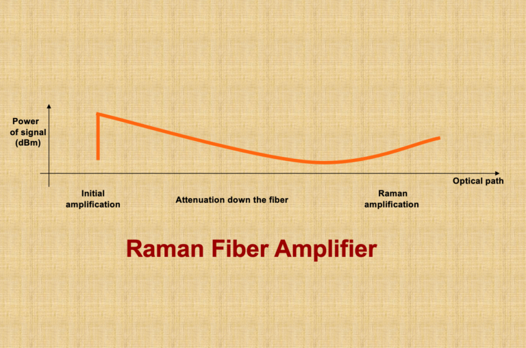
  6. Distributed Amplifiers: These amplifiers, such as those using Raman pumping, provide amplification over an extended length of the optical fiber, distributing amplification across the transmission span.
Scheme of insertion of an OAT

Scheme of insertion of an OAT
Scheme of insertion of an OAR

Applications and Configurations

The application of these OA devices can vary. For instance, a Power Amplifier (PA) might include an optical filter to minimize noise or separate signals in multiwavelength applications. The configurations can range from simple setups like Tx + PA + Rx to more complex arrangements like Tx + BA + LA + PA + Rx, as illustrated in the various schematics provided in the IEC standards.

Building upon the foundational knowledge of Optical Amplifiers (OAs), it’s essential to understand the practical configurations of these devices in optical networks. According to the definitions of Booster Amplifiers (BAs), Pre-amplifiers (PAs), and Line Amplifiers (LAs), and referencing Figure 1 from the IEC standards, we can explore various OA device applications and their configurations. These setups illustrate how OAs are integrated into optical communication systems, each serving a unique purpose in enhancing signal integrity and network performance.

  1. Tx + BA + Rx Configuration: This setup involves a transmitter (Tx), followed by a Booster Amplifier (BA), and then a receiver (Rx). The BA is used right after the transmitter to increase the signal power before it enters the long stretch of the fiber. This configuration is particularly useful in long-haul communication systems where maintaining a strong signal over vast distances is crucial.
  2. Tx + PA + Rx Configuration: Here, the system comprises a transmitter, followed by a Pre-amplifier (PA), and then a receiver. The PA is positioned close to the receiver to improve its sensitivity and to amplify the weakened incoming signal. This setup is ideal for scenarios where the incoming signal strength is low, and enhanced detection is required.
  3. Tx + LA + Rx Configuration: In this configuration, a Line Amplifier (LA) is placed between the transmitter and receiver. The LA’s role is to amplify the signal partway through the transmission path, effectively extending the reach of the communication link. This setup is common in both long-haul and regional networks.
  4. Tx + BA + PA + Rx Configuration: This more complex setup involves both a BA and a PA, with the BA placed after the transmitter and the PA before the receiver. This combination allows for both an initial boost in signal strength and a final amplification to enhance receiver sensitivity, making it suitable for extremely long-distance transmissions or when signals pass through multiple network segments.
  5. Tx + BA + LA + Rx Configuration: Combining a BA and an LA provides a powerful solution for extended reach. The BA boosts the signal post-transmission, and the LA offers additional amplification along the transmission path. This configuration is particularly effective in long-haul networks with significant attenuation.
  6. Tx + LA + PA + Rx Configuration: Here, the LA is used for mid-path amplification, while the PA is employed near the receiver. This setup ensures that the signal is sufficiently amplified both during transmission and before reception, which is vital in networks with long spans and higher signal loss.
  7. Tx + BA + LA + PA + Rx Configuration: This comprehensive setup includes a BA, an LA, and a PA, offering a robust solution for maintaining signal integrity across very long distances and complex network architectures. The BA boosts the initial signal strength, the LA provides necessary mid-path amplification, and the PA ensures that the receiver can effectively detect the signal.

Characteristics of Optical Amplifiers

Each type of OA has specific characteristics that define its performance in different applications, whether single-channel or multichannel. These characteristics include input and output power ranges, wavelength bands, noise figures, reflectance, and maximum tolerable reflectance at input and output, among others.

For instance, in single-channel applications, a Power Amplifier’s characteristics would include an input power range, output power range, power wavelength band, and signal-spontaneous noise figure. In contrast, for multichannel applications, additional parameters like channel allocation, channel input and output power ranges, and channel signal-spontaneous noise figure become relevant.

Optically Amplified Transmitters and Receivers

In the realm of OA subsystems like OATs and OARs, the focus shifts to parameters like bit rate, application code, operating signal wavelength range, and output power range for transmitters, and sensitivity, overload, and bit error ratio for receivers. These parameters are critical in defining the performance and suitability of these subsystems for specific applications.

Understanding Through Practical Examples

To illustrate, consider a scenario in a long-distance fiber optic communication system. Here, a Line Amplifier might be employed to extend the transmission distance. This amplifier would need to have a low noise figure to minimize signal degradation and a high saturation output power to ensure the signal remains strong over long distances. The specific values for these parameters would depend on the system’s requirements, such as the total transmission distance and the number of channels being used.

Advanced Applications of Optical Amplifiers

  1. Long-Haul Communication: In long-haul fiber optic networks, Line Amplifiers (LAs) play a critical role. They are strategically placed at intervals to compensate for signal loss. For example, an LA with a high saturation output power of around +17 dBm and a low noise figure, typically less than 5 dB, can significantly extend the reach of the communication link without the need for electronic regeneration.
  2. Submarine Cables: Submarine communication cables, spanning thousands of kilometers, heavily rely on Distributed Amplifiers, like Raman amplifiers. These amplifiers uniquely boost the signal directly within the fiber, offering a more distributed amplification approach, which is crucial for such extensive undersea networks.
  3. Metropolitan Area Networks: In shorter, more congested networks like those in metropolitan areas, a combination of Booster Amplifiers (BAs) and Pre-amplifiers can be used. A BA, with an output power range of up to +23 dBm, can effectively launch a strong signal into the network, while a Pre-amplifier at the receiving end, with a very low noise figure (as low as 4 dB), enhances the receiver’s sensitivity to weak signals.
  4. Optical Add-Drop Multiplexers (OADMs): In systems using OADMs for channel multiplexing and demultiplexing, Line Amplifiers help in maintaining signal strength across the channels. The ability to handle multiple channels, each potentially with different power levels, is crucial. Here, the channel addition/removal (steady-state) gain response and transient gain response become significant parameters.

Technological Innovations and Challenges

The development of OA technologies is not without challenges. One of the primary concerns is managing the noise, especially in systems with multiple amplifiers. Each amplification stage adds some noise, quantified by the signal-spontaneous noise figure, which can accumulate and degrade the overall signal quality.

Another challenge is the management of Polarization Mode Dispersion (PMD) in Line Amplifiers. PMD can cause different light polarizations to travel at slightly different speeds, leading to signal distortion. Modern LAs are designed to minimize PMD, a critical parameter in high-speed networks.

Future of Optical Amplifiers in Industry

The future of OAs is closely tied to the advancements in fiber optic technology. As data demands continue to skyrocket, the need for more efficient, higher-capacity networks grows. Optical Amplifiers will continue to evolve, with research focusing on higher power outputs, broader wavelength ranges, and more sophisticated noise management techniques.

Innovations like hybrid amplification techniques, combining the benefits of Raman and Erbium-Doped Fiber Amplifiers (EDFAs), are on the horizon. These hybrid systems aim to provide higher performance, especially in terms of power efficiency and noise reduction.

References

ITU-T :https://www.itu.int/en/ITU-T/Pages/default.aspx

Image :https://www.chinacablesbuy.com/guide-to-optical-amplifier.html

Optical networks are the backbone of the internet, carrying vast amounts of data over great distances at the speed of light. However, maintaining signal quality over long fiber runs is a challenge due to a phenomenon known as noise concatenation. Let’s delve into how amplified spontaneous emission (ASE) noise affects Optical Signal-to-Noise Ratio (OSNR) and the performance of optical amplifier chains.

The Challenge of ASE Noise

ASE noise is an inherent byproduct of optical amplification, generated by the spontaneous emission of photons within an optical amplifier. As an optical signal traverses through a chain of amplifiers, ASE noise accumulates, degrading the OSNR with each subsequent amplifier in the chain. This degradation is a crucial consideration in designing long-haul optical transmission systems.

Understanding OSNR

OSNR measures the ratio of signal power to ASE noise power and is a critical parameter for assessing the performance of optical amplifiers. A high OSNR indicates a clean signal with low noise levels, which is vital for ensuring data integrity.

Reference System for OSNR Estimation

As depicted in Figure below), a typical multichannel N span system includes a booster amplifier, N−1 line amplifiers, and a preamplifier. To simplify the estimation of OSNR at the receiver’s input, we make a few assumptions:

Representation of optical line system interfaces (a multichannel N-span system)
  • All optical amplifiers, including the booster and preamplifier, have the same noise figure.
  • The losses of all spans are equal, and thus, the gain of the line amplifiers compensates exactly for the loss.
  • The output powers of the booster and line amplifiers are identical.

Estimating OSNR in a Cascaded System

E1: Master Equation For OSNR

E1: Master Equation For OSNR

Pout is the output power (per channel) of the booster and line amplifiers in dBm, L is the span loss in dB (which is assumed to be equal to the gain of the line amplifiers), GBA is the gain of the optical booster amplifier in dB, NFis the signal-spontaneous noise figure of the optical amplifier in dB, h is Planck’s constant (in mJ·s to be consistent with Pout in dBm), ν is the optical frequency in Hz, νr is the reference bandwidth in Hz (corresponding to c/Br ), N–1 is the total number of line amplifiers.

The OSNR at the receivers can be approximated by considering the output power of the amplifiers, the span loss, the gain of the optical booster amplifier, and the noise figure of the amplifiers. Using constants such as Planck’s constant and the optical frequency, we can derive an equation that sums the ASE noise contributions from all N+1 amplifiers in the chain.

Simplifying the Equation

Under certain conditions, the OSNR equation can be simplified. If the booster amplifier’s gain is similar to that of the line amplifiers, or if the span loss greatly exceeds the booster gain, the equation can be modified to reflect these scenarios. These simplifications help network designers estimate OSNR without complex calculations.

1)          If the gain of the booster amplifier is approximately the same as that of the line amplifiers, i.e., GBA » L, above Equation E1 can be simplified to:

osnr_2

E1-1

2)          The ASE noise from the booster amplifier can be ignored only if the span loss L (resp. the gain of the line amplifier) is much greater than the booster gain GBA. In this case Equation E1-1 can be simplified to:

E1-2

3)          Equation E1-1 is also valid in the case of a single span with only a booster amplifier, e.g., short‑haul multichannel IrDI in Figure 5-5 of [ITU-T G.959.1], in which case it can be modified to:

E1-3

4)          In case of a single span with only a preamplifier, Equation E1 can be modified to:

Practical Implications for Network Design

Understanding the accumulation of ASE noise and its impact on OSNR is crucial for designing reliable optical networks. It informs decisions on amplifier placement, the necessity of signal regeneration, and the overall system architecture. For instance, in a system where the span loss is significantly high, the impact of the booster amplifier on ASE noise may be negligible, allowing for a different design approach.

Conclusion

Noise concatenation is a critical factor in the design and operation of optical networks. By accurately estimating and managing OSNR, network operators can ensure signal quality, minimize error rates, and extend the reach of their optical networks.

In a landscape where data demands are ever-increasing, mastering the intricacies of noise concatenation and OSNR is essential for anyone involved in the design and deployment of optical communication systems.

References

https://www.itu.int/rec/T-REC-G/e

  1. What is a Raman amplifier?

A: A Raman amplifier is a type of optical amplifier that utilizes stimulated Raman scattering (SRS) to amplify optical signals in fiber-optic communication systems.

  1. How does a Raman amplifier work?

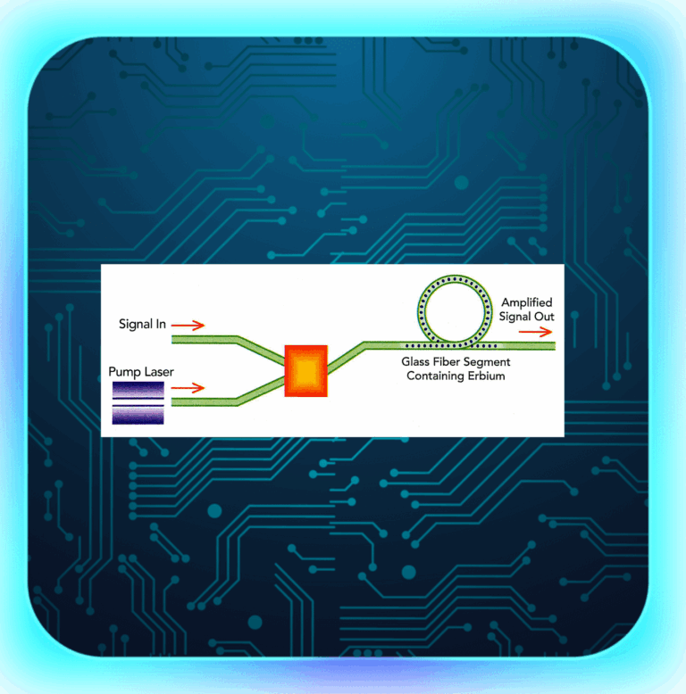
A: Raman amplification occurs when a high-power pump laser interacts with the optical signal in the transmission fiber, causing energy transfer from the pump wavelength to the signal wavelength through stimulated Raman scattering, thus amplifying the signal.

  1. What is the difference between a Raman amplifier and an erbium-doped fiber amplifier (EDFA)?

A: A Raman amplifier uses stimulated Raman scattering in the transmission fiber for amplification, while an EDFA uses erbium-doped fiber as the gain medium. Raman amplifiers can provide gain over a broader wavelength range and have lower noise compared to EDFAs.

  1. What are the advantages of Raman amplifiers?

A: Advantages of Raman amplifiers include broader gain bandwidth, lower noise, and better performance in combating nonlinear effects compared to other optical amplifiers, such as EDFAs.

  1. What is the typical gain bandwidth of a Raman amplifier?

A: The typical gain bandwidth of a Raman amplifier can be up to 100 nm or more, depending on the pump laser configuration and fiber properties.

  1. What are the key components of a Raman amplifier?

A: Key components of a Raman amplifier include high-power pump lasers, wavelength division multiplexers (WDMs) or couplers, and the transmission fiber itself, which serves as the gain medium.

  1. How do Raman amplifiers reduce nonlinear effects in optical networks?

A: Raman amplifiers can be configured to provide distributed gain along the transmission fiber, reducing the peak power of the optical signals and thus mitigating nonlinear effects such as self-phase modulation and cross-phase modulation.

  1. What are the different types of Raman amplifiers?

A: Raman amplifiers can be classified as discrete Raman amplifiers (DRAs) and distributed Raman amplifiers (DRAs). DRAs use a separate section of fiber as the gain medium, while DRAs provide gain directly within the transmission fiber.

  1. How is a Raman amplifier pump laser configured?

A: Raman amplifier pump lasers can be configured in various ways, such as co-propagating (pump and signal travel in the same direction) or counter-propagating (pump and signal travel in opposite directions) to optimize performance.

  1. What are the safety concerns related to Raman amplifiers?

A: The high-power pump lasers used in Raman amplifiers can pose safety risks, including damage to optical components and potential harm to technicians if proper safety precautions are not followed.

  1. Can Raman amplifiers be used in combination with other optical amplifiers?

A: Yes, Raman amplifiers can be used in combination with other optical amplifiers, such as EDFAs, to optimize system performance by leveraging the advantages of each amplifier type.

  1. How does the choice of fiber type impact Raman amplification?

A: The choice of fiber type can impact Raman amplification efficiency, as different fiber types exhibit varying Raman gain coefficients and effective area, which affect the gain and noise performance.

  1. What is the Raman gain coefficient?

A: The Raman gain coefficient is a measure of the efficiency of the Raman scattering process in a specific fiber. A higher Raman gain coefficient indicates more efficient energy transfer from the pump laser to the optical signal.

  1. What factors impact the performance of a Raman amplifier?

A: Factors impacting Raman amplifier performance include pump laser power and wavelength, fiber type and length, signal wavelength, and the presence of other nonlinear effects.

  1. How does temperature affect Raman amplifier performance?

A: Temperature can affect Raman amplifier performance by influencing the Raman gain coefficient and the efficiency of the stimulated Raman scattering process. Proper temperature management is essential for optimal Raman amplifier performance.

  1. What is the role of a Raman pump combiner?

A: A Raman pump combiner is a device used to combine the output of multiple high-power pump lasers, providing a single high-power pump source to optimize Raman amplifier performance.

  1. How does polarization mode dispersion (PMD) impact Raman amplifiers?

A: PMD can affect the performance of Raman amplifiers by causing variations in the gain and noise characteristics for different polarization states, potentially leading to signal degradation.

  1. How do Raman amplifiers impact optical signal-to-noise ratio (OSNR)?

A: Raman amplifiers can improve the OSNR by providing distributed gain along the transmission fiber and reducing the peak power of the optical signals, which helps to mitigate nonlinear effects and improve signal quality.

  1. What are the challenges in implementing Raman amplifiers?

A: Challenges in implementing Raman amplifiers include the need for high-power pump lasers, proper safety precautions, temperature management, and potential interactions with other nonlinear effects in the fiber-optic system.

  1. What is the future of Raman amplifiers in optical networks?

A: The future of Raman amplifiers in optical networks includes further research and development to optimize performance, reduce costs, and integrate Raman amplifiers with other emerging technologies, such as software-defined networking (SDN), to enable more intelligent and adaptive optical networks.


1. Introduction

A reboot is a process of restarting a device, which can help to resolve many issues that may arise during the device’s operation. There are two types of reboots – cold and warm reboots. Both types of reboots are commonly used in optical networking, but there are significant differences between them. In the following sections, we will discuss these differences in detail and help you determine which type of reboot is best for your network.

2. What is a Cold Reboot?

A cold reboot is a complete shutdown of a device followed by a restart. During a cold reboot, the device’s power is turned off and then turned back on after a few seconds. A cold reboot clears all the data stored in the device’s memory and restarts it from scratch. This process is time-consuming and can take several minutes to complete.

3. Advantages of a Cold Reboot

A cold reboot is useful in situations where a device is not responding or has crashed due to software or hardware issues. A cold reboot clears all the data stored in the device’s memory, including any temporary files or cached data that may be causing the problem. This helps to restore the device to its original state and can often resolve the issue.

4. Disadvantages of a Cold Reboot

A cold reboot can be time-consuming and can cause downtime for the network. During the reboot process, the device is unavailable, which can cause disruption to the network’s operations. Additionally, a cold reboot clears all the data stored in the device’s memory, including any unsaved work, which can cause data loss.

5. What is a Warm Reboot?

A warm reboot is a restart of a device without turning off its power. During a warm reboot, the device’s software is restarted while the hardware remains on. This process is faster than a cold reboot and typically takes only a few seconds to complete.

6. Advantages of a Warm Reboot

A warm reboot is useful in situations where a device is not responding or has crashed due to software issues. Since a warm reboot does not clear all the data stored in the device’s memory, it can often restore the device

to its original state without causing data loss. Additionally, a warm reboot is faster than a cold reboot, which minimizes downtime for the network.

7. Disadvantages of a Warm Reboot

A warm reboot may not be effective in resolving hardware issues that may be causing the device to crash. Additionally, a warm reboot may not clear all the data stored in the device’s memory, which may cause the device to continue to malfunction.

8. Which One Should You Use?

The decision to perform a cold or warm reboot depends on the nature of the problem and the impact of downtime on the network’s operations. If the issue is severe and requires a complete reset of the device, a cold reboot is recommended. On the other hand, if the problem is minor and can be resolved by restarting the device’s software, a warm reboot is more appropriate.

9. How to Perform a Cold or Warm Reboot in Optical Networking?

Performing a cold or warm reboot in optical networking is a straightforward process. To perform a cold reboot, simply turn off the device’s power, wait a few seconds, and then turn it back on. To perform a warm reboot, use the device’s software to restart it while leaving the hardware on. However, it is essential to follow the manufacturer’s guidelines and best practices when performing reboots to avoid any negative impact on the network’s operations.

10. Best Practices for Cold and Warm Reboots

Performing reboots in optical networking requires careful planning and execution to minimize downtime and ensure the network’s smooth functioning. Here are some best practices to follow when performing cold or warm reboots:

  • Perform reboots during off-peak hours to minimize disruption to the network’s operations.
  • Follow the manufacturer’s guidelines for performing reboots to avoid any negative impact on the network.
  • Back up all critical data before performing a cold reboot to avoid data loss.
  • Notify all users before performing a cold reboot to minimize disruption and avoid data loss.
  • Monitor the network closely after a reboot to ensure that everything is functioning correctly.

11. Common Mistakes to Avoid during Reboots

Performing reboots in optical networking can be complex and requires careful planning and execution to avoid any negative impact on the network’s operations. Here are some common mistakes to avoid when performing reboots:

  • Failing to back up critical data before performing a cold reboot, which can result in data loss.
  • Performing reboots during peak hours, which can cause disruption to the network’s operations.
  • Failing to follow the manufacturer’s guidelines for performing reboots, which can result in system crashes and data loss.
  • Failing to notify all users before performing a cold reboot, which can cause disruption and data loss.

12. Conclusion

In conclusion, both cold and warm reboots are essential tools for resolving issues in optical networking. However, they have significant differences in terms of speed, data loss, and impact on network operations. Understanding these differences can help you make the right decision when faced with a network issue that requires a reboot.

13. FAQs

  1. What is the difference between a cold and a warm reboot? A cold reboot involves a complete shutdown of a device followed by a restart, while a warm reboot is a restart of a device without turning off its power.
  2. Can I perform a cold or warm reboot on any device in an optical network? Yes, you can perform a cold or warm reboot on any device in an optical network, but it is essential to follow the manufacturer’s guidelines and best practices.
  3. Is it necessary to perform regular reboots in optical networking? No, it is
  4. not necessary to perform regular reboots in optical networking. However, if a device is experiencing issues, a reboot may be necessary to resolve the problem.
  5. Can reboots cause data loss? Yes, performing a cold reboot can cause data loss if critical data is not backed up before the reboot. However, a warm reboot typically does not cause data loss.
  6. What are some other reasons for network outages besides system crashes? Network outages can occur due to various reasons, including power outages, hardware failures, software issues, and human error. Regular maintenance and monitoring can help prevent these issues and minimize downtime.