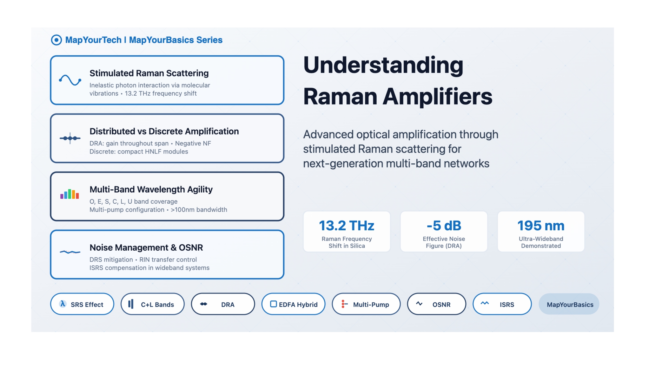
Understanding Raman Amplifiers
Raman amplifiers represent a paradigm shift in optical amplification technology. Unlike conventional amplifiers that rely on rare-earth doped fibers (such as EDFAs), Raman amplifiers exploit the intrinsic nonlinear optical properties of the transmission fiber itself. By leveraging the Stimulated Raman Scattering (SRS) effect—a fundamental quantum mechanical phenomenon—these amplifiers can provide gain at virtually any wavelength across the optical spectrum, making them indispensable for next-generation multi-band optical networks.
1. The Physics of Stimulated Raman Scattering
Stimulated Raman Scattering is an inelastic scattering process that occurs when high-intensity pump light interacts with the molecular vibrations (optical phonons) in the silica glass structure of an optical fiber. When a pump photon encounters a molecule in its ground state, it can transfer a portion of its energy to excite the molecule's vibrational modes, while simultaneously generating a lower-energy (longer-wavelength) photon.
Interactive Visualization: SRS Amplification Process
This frequency shift of approximately 13.2 THz in silica fiber is remarkably consistent and corresponds to the vibrational resonance of Si-O bonds. This means that if a pump laser operates at 1450 nm, it can amplify signals around 1550 nm (C-band), as this wavelength separation corresponds to the ~13.2 THz Raman shift.
2. Energy Level Transitions and Gain Mechanism
Absorption
Emission
Coefficient
🎯 Key Insight: Virtual State Transition
Unlike traditional amplifiers where electrons transition between discrete energy levels, Raman amplification involves a virtual state—an intermediate quantum state that exists only momentarily. The pump photon elevates the molecule to this virtual state, from which it immediately relaxes to a real vibrational energy level, emitting a Stokes photon in the process. This mechanism is what enables the broad gain bandwidth characteristic of Raman amplifiers.
3. Distributed vs. Discrete Raman Amplification
📡 Distributed Raman Amplifier (DRA)
Gain Medium: The transmission fiber itself (50-100 km spans)
Pump Injection: High-power pump lasers inject light counter-propagating (backward) or co-propagating (forward) with the signal
Key Benefit: Provides gain throughout the entire fiber span, effectively raising the minimum signal power level and dramatically improving OSNR
Noise Figure: Can achieve effective negative noise figures (-2 to -5 dB) due to distributed gain
Applications: Ultra-long-haul transmission, submarine systems, remote pumping scenarios
🔧 Discrete Raman Amplifier
Gain Medium: Dedicated highly nonlinear fiber (HNLF) coil, typically several kilometers
Configuration: Compact module similar to EDFA architecture
Key Benefit: Higher gain per unit length, easier to integrate into existing infrastructure
Noise Figure: Typical NF of 4-6 dB, comparable to EDFAs
Applications: Metro networks, wavelength conversion, gain equalization in multi-band systems
Distributed Raman Amplification Architecture
Signal Power Evolution Along Fiber Span
DRA maintains higher signal power throughout the span, improving OSNR and reducing nonlinear impairments
4. Wavelength Agility and Multi-Band Operation
One of Raman amplification's most revolutionary features is its wavelength flexibility. Unlike EDFAs which are constrained to C and L bands by erbium's energy level structure, Raman amplifiers can provide gain at virtually any wavelength—provided appropriate pump lasers are available at shorter wavelengths (with the required ~13.2 THz frequency offset).
(1260-1360 nm) E-Band
(1360-1460 nm) S-Band
(1460-1530 nm) C-Band
(1530-1565 nm) L-Band
(1565-1625 nm)
Raman amplifiers enable multi-band operation across O, E, S, C, L, and U bands
💡 Multi-Pump Wavelength Configuration
By employing multiple pump lasers at different wavelengths and carefully optimizing their power levels, engineers can tailor the gain spectrum to achieve remarkably flat gain profiles over bandwidths exceeding 100 nm. This technique enables:
- Gain flattening across C+L bands (spanning ~80 nm)
- Custom gain tilt compensation for specific fiber types
- Dynamic gain equalization in response to channel loading changes
- Ultra-wideband operation from 1410 nm to 1605 nm (195 nm bandwidth)
5. Pump Configurations and Efficiency
Backward vs. Forward Pumping
Backward Pumped Configuration
Advantage: Minimal pump-to-signal noise transfer due to short interaction time
Forward Pumped Configuration
Advantage: Higher gain efficiency, but increased Relative Intensity Noise (RIN) transfer
⚡ Pump Power Requirements
Raman amplification requires significantly higher pump powers compared to EDFAs—typically in the range of 300 mW to 1 W per pump wavelength for distributed systems. This high power requirement presents several challenges:
- Safety concerns: High optical power levels necessitate robust laser safety protocols
- Heat dissipation: Requires active cooling and thermal management
- Pump laser cost: High-power pump diodes significantly increase system cost
- Power efficiency: Overall wall-plug efficiency is lower than EDFAs (typically 5-10% vs. 30-40%)
Pump Laser Technologies
1. Fiber Bragg Grating (FBG) Stabilized Diodes
• Wavelength-locked single-emitter diodes
• Power: 200-500 mW per diode
• Low RIN, high spectral purity
2. Multiplexed Diode Arrays
• Multiple diodes wavelength-combined using WDM couplers
• Total power: 1-5 W
• Cost-effective for high-power applications
3. Cascaded Raman Fiber Lasers
• Uses cascaded Raman shifts in fiber cavity
• Can reach wavelengths difficult for direct diode emission
• Power: 100 mW - 10 W
4. Cladding-Pumped Fiber Lasers
• Ytterbium-doped fiber lasers as Raman pumps
• Power: Multi-watt capability
• Used for discrete Raman amplifiers
6. Noise Sources and OSNR Performance
While Raman amplifiers offer unique advantages, they also introduce specific noise mechanisms that must be carefully managed for optimal system performance.
Emission (ASE)
Scattering (DRS)
Transfer
Interactions
Distributed Raman:
• Effective NF: -2 to -5 dB
• Best for long-haul systems
Discrete Raman:
• Typical NF: 4-6 dB
• Comparable to EDFAs
Hybrid EDFA+Raman:
• Combined NF: 2-4 dB
• Optimizes both approaches
🎚️ Double Rayleigh Scattering (DRS)
A unique impairment in Raman amplifiers is Double Rayleigh Scattering. When light propagates through fiber, a small fraction is scattered backward due to microscopic density fluctuations (Rayleigh scattering). In a Raman amplifier, this back-scattered light can be amplified and scattered forward again, creating a delayed, distorted copy of the original signal. This multi-path interference degrades signal quality and limits system performance, particularly in long distributed Raman amplifier spans.
7. Inter-Channel SRS (ISRS) in Wideband Systems
In ultra-wideband WDM systems, a phenomenon called Inter-Channel Stimulated Raman Scattering (ISRS) becomes critically important. Since SRS causes energy transfer from shorter wavelengths to longer wavelengths, in a multi-channel system the shorter-wavelength channels effectively act as pumps for longer-wavelength channels.
ISRS Power Tilt Effect
Short-wavelength channels lose power while long-wavelength channels gain power, creating spectral tilt
The ISRS effect is particularly pronounced when the total system bandwidth exceeds ~10-15 THz. For a system spanning S+C+L bands (total ~15 THz), channels in the S-band can lose several dB of power while L-band channels gain power. This must be compensated through:
- Pre-emphasis: Launching S-band channels with higher power
- Dynamic gain equalizers (DGEs): Active spectral shaping at amplifier sites
- Per-band link control: Independent power management for each band
- Advanced DSP algorithms: Digital compensation in coherent receivers
8. Advantages, Challenges, and Trade-offs
✅ Key Advantages
- Wavelength flexibility: Gain at any wavelength with appropriate pumps
- Broadband operation: >100 nm bandwidth demonstrated with multi-pump configurations
- Superior noise performance (DRA): Negative effective noise figures improve OSNR
- Reduced nonlinear impairments: Distributed gain maintains lower peak powers
- Gain spectrum tailoring: Customizable gain profiles through pump optimization
- Remote pumping capability: Enables amplification at inaccessible locations
- Multi-band enabler: Critical technology for O, E, S, U band expansion
⚠️ Technical Challenges
- High pump power requirements: 300 mW - 1 W per pump wavelength needed
- Lower power efficiency: 5-10% vs. 30-40% for EDFAs
- Increased system complexity: Multiple pump lasers, sophisticated control systems
- Higher cost: Expensive high-power pump diodes and control electronics
- RIN transfer: Pump laser noise can degrade signal quality (forward pumping)
- Double Rayleigh scattering: Creates multi-path interference in long spans
- Pump-pump interactions: Crosstalk between multiple pump wavelengths
- ISRS management: Requires complex compensation in wideband systems
- Safety concerns: High optical power levels require stringent laser safety measures
Comparison with Other Amplifier Technologies
| Parameter | EDFA | Raman (DRA) | Raman (Discrete) |
|---|---|---|---|
| Operating Bands | C, L bands only | Any band (O,E,S,C,L,U) | Any band (O,E,S,C,L,U) |
| Noise Figure | 4-6 dB | -2 to -5 dB (effective) | 4-6 dB |
| Gain | 30-50 dB | 5-15 dB (per span) | 15-25 dB |
| Bandwidth | 35-40 nm | >100 nm (multi-pump) | >100 nm (multi-pump) |
| Power Efficiency | 30-40% | 5-10% | 5-10% |
| Cost | Low (mature technology) | High (pump lasers) | Medium-High |
| Complexity | Low | High | Medium |
Hybrid EDFA + Raman Configuration
Hybrid System Architecture
Hybrid configuration combines EDFA's high gain with Raman's low noise for optimal performance
9. Advanced Topics and Recent Advances
Raman Gain Coefficient and Effective Area
The Raman gain coefficient (gR) in silica fiber is approximately 1 × 10-13 m/W at the peak of the Raman gain spectrum (13.2 THz shift). The actual gain experienced by a signal depends on several factors:
Where:
- G = Raman gain (linear)
- gR = Raman gain coefficient
- Ppump = Pump power
- Leff = Effective fiber length (accounts for pump depletion)
- Aeff = Effective mode area (~80 μm² for standard SMF, ~10-15 μm² for HNLF)
📊 Practical Gain Calculations
For a typical distributed Raman system:
- 50 km span of standard single-mode fiber (SSMF)
- Backward pump power: 500 mW at 1450 nm
- Signal wavelength: 1550 nm (C-band)
- Expected Raman gain: 8-12 dB
This modest gain distributed over 50 km significantly improves the minimum signal power level, yielding an effective noise figure improvement of 3-5 dB compared to discrete amplification only at span ends.
Fiber Type Considerations
The choice of fiber significantly impacts Raman amplifier performance:
| Fiber Type | Aeff (μm²) | Raman Efficiency | Best Application |
|---|---|---|---|
| Standard SMF (G.652) | 80-85 | Moderate | Distributed amplification in existing infrastructure |
| Large Effective Area (G.654) | 110-150 | Lower | Submarine systems, reduced nonlinearity priority |
| Highly Nonlinear Fiber (HNLF) | 10-15 | Very High | Discrete Raman amplifiers, parametric devices |
| Dispersion-Compensating Fiber (DCF) | 15-20 | High | Combined dispersion compensation and amplification |
Higher-Order Raman Effects
Cascaded Raman Scattering
At very high pump powers, the first-order Stokes wave can itself act as a pump for second-order Raman scattering, creating a cascade effect:
Pump (λ₀) → 1st Stokes (λ₀ + 100 nm) → 2nd Stokes (λ₀ + 200 nm) → 3rd Stokes (λ₀ + 300 nm)
This cascading enables ultra-wideband amplification but requires careful pump power management to avoid instabilities and pump depletion effects.
Polarization Effects
Raman gain exhibits polarization dependence due to the anisotropic nature of the scattering process. In standard fiber, this effect averages out due to random birefringence, but in short lengths or specialty fibers:
- Polarization Dependent Gain (PDG): Can reach 3-5 dB in worst case
- Mitigation techniques: Polarization multiplexed pumps, polarization scrambling
- PMD interaction: Raman gain can be affected by polarization mode dispersion in long spans
Quantum Noise Perspective
⚛️ Fundamental Noise Limits
Like all phase-insensitive amplifiers, Raman amplifiers are subject to the quantum noise limit, which dictates a minimum noise figure of 3 dB (corresponding to the addition of one photon of noise per mode). However, distributed Raman amplification achieves effective noise figures below this limit by:
- Distributing gain along the fiber, maintaining higher signal levels throughout
- Reducing the impact of subsequent amplifier noise contributions
- Effectively "pushing back" the dominant noise source in the amplifier chain
Note: This doesn't violate quantum mechanics—the distributed Raman section itself still adds quantum noise, but the system-level effective noise figure (referenced to the fiber input) can be negative.
Temperature Effects
🌡️ Temperature Dependence
Raman gain exhibits relatively weak temperature dependence compared to EDFAs:
- Gain variation: ~0.01 dB/°C (vs. ~0.05 dB/°C for EDFA)
- Wavelength drift: Negligible (gain spectrum is fiber property, not dopant-dependent)
- Pump laser wavelength drift: 0.1 nm/°C typical for FBG-stabilized diodes
- Mitigation: Thermoelectric cooling (TEC) for pump lasers, temperature compensation algorithms
Recent Breakthrough Achievements
🚀 State-of-the-Art Demonstrations
- Ultra-wideband hybrid amplifiers: Demonstrations of distributed-discrete Raman covering 1410-1605 nm (195 nm span), encompassing E+S+C+L bands
- U-band Raman amplification: Using EDFA ASE as a broadband incoherent pump source to enable gain beyond 1625 nm
- Machine learning optimization: AI-driven pump configuration algorithms for adaptive gain flattening
- Hollow-core fiber integration: Extending Raman techniques to novel fiber types for ultra-low latency applications
- Negative effective noise figures: DRA systems achieving -5 dB effective NF in commercial deployments
Key Application Areas
Ultra-long-haul transoceanic cables with 50+ year operational lifetimes
Enabling S+C+L and beyond for 100+ Tb/s fiber capacity
Discrete Raman for flexible wavelength support in city networks
Distributed fiber sensing with Raman-based interrogation
Amplification at remote, unpowered sites via optical pump delivery
Maintaining lower peak powers to reduce four-wave mixing and cross-phase modulation
Future Research Directions
🔭 Emerging Trends
- Higher-order Raman cascades: Exploiting second and third-order Raman shifts for even broader bandwidth
- Quantum-limited amplification: Approaching fundamental quantum noise limits through phase-sensitive Raman amplification
- Multicore and spatial division multiplexing: Raman amplification in advanced fiber geometries
- Integrated photonics: On-chip Raman amplifiers using silicon and III-V platforms
- Energy-efficient pumping: Novel pump laser architectures to improve wall-plug efficiency
- AI-optimized control: Real-time adaptive pump power and wavelength optimization using machine learning
Network Implementation Strategies
Add Raman pumping to existing EDFA-amplified links without replacing infrastructure. Typical gain: 5-8 dB additional, enabling 20-40% reach extension or capacity upgrade.
Design system from scratch with optimized hybrid amplification. Enables aggressive multi-band architectures (S+C+L) with 15+ THz total bandwidth.
System Design Trade-offs
⚙️ Engineering Considerations
System designers must balance multiple competing factors:
- OSNR vs. Cost: Distributed Raman improves OSNR by 3-5 dB but increases amplifier costs by 2-3×
- Bandwidth vs. Complexity: Ultra-wideband operation requires 6-12 pump wavelengths with sophisticated control algorithms
- Gain flatness vs. Efficiency: Flatter gain profiles often require additional pump power and filtering
- Reach vs. Nonlinearity: Higher launch powers improve reach but increase FWM, SPM, and XPM impairments
- Forward vs. Backward pumping: Trading gain efficiency for noise performance
Measurement and Characterization
Accurate characterization of Raman amplifiers requires specialized test equipment and methodologies:
- Gain Spectrum: Measured using tunable laser source and optical spectrum analyzer
- Noise Figure: Requires optical noise measurement or interpolation techniques
- Pump-to-Signal RIN Transfer: Critical for forward-pumped configurations
- Gain Saturation: Response to varying input signal powers
- Transient Response: Behavior during channel add/drop events
- • High-power optical sources (pump simulation)
- • Optical spectrum analyzer with >80 dB dynamic range
- • WDM signal generators (multi-channel testing)
- • Long fiber spools (80-100 km for DRA testing)
- • Optical time-domain reflectometer (OTDR)
Summary and Key Takeaways
🎓 Essential Concepts to Remember
- SRS is a nonlinear optical process where pump photons transfer energy to signal photons through molecular vibrations, with a characteristic 13.2 THz frequency shift in silica
- Wavelength agility is the killer feature—Raman gain can be achieved at any wavelength with appropriate pumping, enabling multi-band operation
- Distributed vs. discrete—DRA offers superior OSNR but requires high pump power; discrete Raman provides flexible wavelength support in compact modules
- Backward pumping minimizes noise while forward pumping maximizes efficiency—hybrid bidirectional pumping offers balanced performance
- ISRS creates spectral tilt in wideband systems, requiring active compensation through DGEs or pre-emphasis
- Trade-offs are inherent—Raman amplifiers sacrifice power efficiency and increase complexity in exchange for bandwidth, flexibility, and noise performance
- Hybrid EDFA+Raman architectures combine the best of both technologies for optimal real-world system performance
- The future is multi-band—as networks expand beyond C+L, Raman amplification becomes increasingly critical for enabling next-generation capacity
Conclusion
Raman amplifiers represent one of the most versatile and powerful tools in modern optical communications. By exploiting the intrinsic nonlinear properties of optical fiber through stimulated Raman scattering, these amplifiers enable unprecedented wavelength flexibility, ultra-wideband operation, and superior noise performance in distributed configurations.
While challenges remain—particularly in terms of pump power requirements, system complexity, and cost—the unique capabilities of Raman amplification make it indispensable for next-generation optical networks. As the industry pushes toward multi-band transmission systems capable of 100+ Tb/s fiber capacity, Raman amplifiers will continue to play a critical enabling role, bridging the gap between conventional C/L-band EDFAs and emerging ultra-wideband network architectures.
The future of optical networking is multi-band, and Raman amplification is the key technology making that future possible.
Developed by MapYourTech Team
For educational purposes in optical networking and DWDM systems
Note: This guide is based on industry standards, best practices, and real-world implementation experiences. Specific implementations may vary based on equipment vendors, network topology, and regulatory requirements. Always consult with qualified network engineers and follow vendor documentation for actual deployments.
Unlock Premium Content
Join over 400K+ optical network professionals worldwide. Access premium courses, advanced engineering tools, and exclusive industry insights.
Already have an account? Log in here