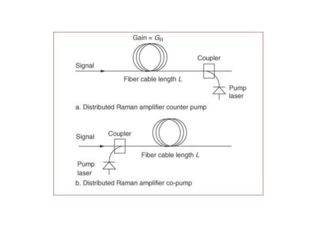
A Raman amplifier is a well-known amplifier configuration. This amplifier uses conventional fiber (rather doped fibers), which may be co-or counter-pumped to provide amplification over a wavelength range which is a function of the pump wavelength. The Raman amplifier relies upon forward or backward stimulated Raman scattering. Typically, the pump source is selected to have a wavelength of around 100 nm below the wavelength over which amplification is required.
Keynotes of using Raman Amplifiers:
- Its usage improves the overall gain characteristics of high capacity optical wavelength division multiplexed (WDM) communications systems.
- Its usage do not attenuate signals outside the wavelength range over which amplification takes place.
- it is usual to provide a separate pump sources for each wavelength required in form of Raman fibre lasers or semiconductor pumps.
- Multiple lasers increases the overall costs of Raman amplifiers.
- Raman Amplifiers are very sensitive to input power so they are always used with EDFA in cascaded fashion.( a small change at input will result in high output power change and thus subsequent components may suffer)
- Power consumption is very high as multiple lasers are used.
- Always keep output shut-off while integrating Raman in a link as high power lasers are dangerous to personnel too.
- Raman ampliers are typically pumped using unpolarized pump beams.i.e (both the pump and the signal propagate in the fundamental mode, supports two orthogonal polarization states in each mode. Thus, even though the fiber is single mode, the pump and signal may propagate in orthogonal polarizations.)
Distributed (Raman) Gain Improved Transmission Systems
Figure 1 shows a conventional transmission system using erbium-doped fiber amplifiers (EDFAs) to amplify the signal. The signal power in the transmission line is shown; at the output of the EDFA the signal power is high. However, nonlinear effects limit the amount of amplification of the signal. The signal is attenuated along the transmission line. In addition, the minimum signal level limits the Optical Signal to Noise Ratio (OSNR) of the transmission. So the transmission distance between each amplifier point is limited by nonlinear effects at the high signal level right after amplification and the minimum allowable OSNR just before amplification.

Figure 2. Amplification scheme using distributed Raman amplification together with lumped EDFAs
By comparison, Figure 2 shows a scenario where distributed Raman amplification is used. In this hybrid version with backward propagating pumps and EDFAs, the signal power level evolves as shown by the red curves. At the end of the link, the signal is amplified by the Raman pump, and the OSNR is thereby improved. The input power level can also be lowered, as Raman amplification keeps the signal from the noise limit. The lower input power mitigates the non-linearities in the system. Forward propagating pumps or a combination of both forward and backward propagating pumps may be used. Installing transmission fibers that have been designed and optimized to take full advantage of the Raman technology allows system designs with higher capacity and lower cost.
Characteristics of Raman-Optimized Fibers
Fibers optimized for Raman amplification offer the following characteristics:
- high Raman gain efficiency
- low attenuation at signal and pump wavelengths
- low zero dispersion wavelength.

Optical Communications & Network Automation Expert | Author of 3 Books for Optical Engineers | Founder, MapYourTech
Optical networking engineer with nearly two decades of experience across DWDM, OTN, coherent optics, submarine systems, and cloud infrastructure. Founder of MapYourTech. Read full bio →
Follow on LinkedIn