OTN Synchronization Methods for 5G Networks: In-Band vs Out-of-Band Solutions
A comprehensive technical analysis for optical network engineers, 5G transport planners, and network architects making equipment selection decisions for nanosecond-precision timing distribution
Introduction
The deployment of fifth-generation mobile networks introduces timing requirements that are orders of magnitude more stringent than those of previous cellular technologies. Where 4G LTE systems could tolerate phase errors on the order of 1.5 microseconds for time-division duplex operation, 5G New Radio networks demand phase alignment within 130 nanoseconds between cooperating radio units. This represents a reduction in error budget by more than a factor of ten, fundamentally changing the way network operators must approach synchronization architecture.
Optical Transport Network infrastructure, which forms the backbone of most metro and long-haul networks, was historically designed for frequency synchronization using mechanisms derived from Synchronous Digital Hierarchy technology. The asynchronous nature of OTN mapping, specifically the Generic Mapping Procedure that uses variable stuffing bytes to adapt client signals into fixed-rate optical payload units, introduces packet delay variation that destroys the nanosecond-level timing precision required by 5G radio access networks. This creates a critical challenge: how to transport IEEE 1588 Precision Time Protocol messages across OTN networks without accumulating jitter that exceeds the 5G timing budget.
This article examines three fundamentally different approaches to solving the OTN synchronization challenge for 5G deployments. The first two methods, classified as in-band solutions, attempt to carry timing information within the OTN frame structure itself. These include using the OTN frame overhead and the OTN Synchronization Message Channel defined in ITU-T G.709 Amendment 3. The third approach, classified as an out-of-band solution, uses the Optical Supervisory Channel that operates on a separate wavelength outside the client data path. Each method presents distinct trade-offs in terms of jitter performance, implementation complexity, equipment vendor support, and operational readiness for production 5G networks.
The decision framework presented here is intended for optical network architects, 5G transport planners, and procurement teams who must select equipment and design synchronization architectures that will support multi-vendor 5G radio deployments over the next decade. The analysis focuses on technical performance, standardization maturity, and real-world deployment considerations, providing the information necessary to make equipment selection decisions that may involve millions of dollars in capital expenditure and directly impact the quality of service for 5G subscribers.
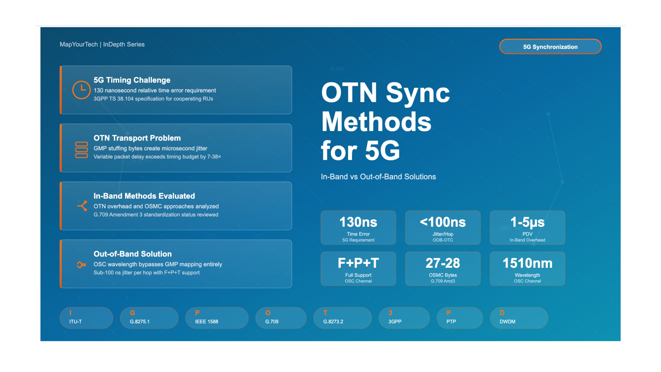
Figure 1: Technical Decision Framework for 5G Synchronization Over OTN Networks — This decision tree is derived from comprehensive analysis of ITU-T standards (G.8275.1, G.8273.2, G.709, G.8251, G.8262.1) and 3GPP specifications (TS 38.104). The framework shows that only out-of-band transport using the Optical Supervisory Channel can reliably meet the 130 nanosecond relative time error requirement for 5G NR TDD networks, as in-band methods introduce packet delay variation that exceeds the timing budget by one to two orders of magnitude.
1. Why 5G Demands Nanosecond-Precision Timing Over OTN
Understanding the specific timing requirements of 5G New Radio technology is essential context for evaluating OTN synchronization methods. Unlike frequency-division duplex systems that use separate frequency bands for uplink and downlink transmission, 5G relies extensively on time-division duplex operation where the same frequency band is time-multiplexed between uplink and downlink. This approach maximizes spectral efficiency but creates an absolute requirement for phase synchronization between base stations.
1.1 TDD Synchronization Requirements and Interference Mitigation
In a 5G TDD network, base stations within the same geographic area must transmit and receive on precisely synchronized time slots. If one base station begins its downlink transmission while a neighboring base station is still in receive mode, the transmitted signal from the first base station will appear as interference to the second base station's uplink reception. This cross-link interference can completely destroy the ability of the receiving base station to decode weak uplink signals from mobile devices at cell edges.
The 3GPP standards specify that cooperating base stations must maintain relative time error below 3 microseconds for basic TDD operation. However, advanced features including coordinated multipoint transmission, massive MIMO beamforming, and carrier aggregation across TDD bands require phase alignment within 130 nanoseconds. This tighter requirement comes from the need to coherently combine signals from multiple transmission points, where phase errors translate directly into destructive interference and reduced signal quality.
1.2 Timing Budget Allocation Through Network Layers
The total 130 nanosecond relative time error budget must be allocated across the entire timing distribution chain, from the primary reference time clock at the network core through multiple layers of packet network equipment to the radio units at cell sites. A typical budget allocation might reserve 30 nanoseconds for the PRTC source and holdover performance, 50 nanoseconds for accumulated jitter through the transport network, and 50 nanoseconds for the final hop synchronization and radio processing.
When PTP packets traverse an OTN network segment, the jitter introduced by that segment consumes a portion of the 50 nanosecond transport network budget. If a single OTN hop introduces 5 microseconds of peak-to-peak jitter, as can occur with standard GMP mapping, the entire timing budget is exceeded by nearly two orders of magnitude. This explains why legacy OTN mapping approaches are fundamentally incompatible with 5G timing requirements and necessitates new synchronization methods.
Critical Requirement:
5G networks using coordinated multipoint and advanced MIMO techniques require relative phase alignment between radio units to be maintained within 130 nanoseconds. Standard OTN mapping can introduce jitter exceeding 5 microseconds, making it unsuitable without specialized synchronization mechanisms.
1.3 Why Traditional Synchronization Methods Fail Over OTN
Earlier generations of mobile networks relied on Synchronous Ethernet for frequency distribution and GPS receivers at every cell site for phase and time information. SyncE operates at the physical layer, recovering the clock from the actual line rate of the Ethernet signal. This approach works well for frequency synchronization, delivering stability on the order of parts per billion, but it cannot carry phase or time-of-day information. Additionally, when an Ethernet signal is mapped into an OTN container using GMP, the physical layer clock relationship is broken because the client signal and the OTN signal operate at different, unrelated rates with the difference absorbed by variable stuffing bytes.
GPS and GNSS receivers provide excellent absolute time accuracy, typically within 30 nanoseconds of UTC when properly calibrated. However, deploying GPS receivers at thousands of cell sites creates operational challenges including antenna installation, cable routing to avoid signal loss, vulnerability to jamming and spoofing, and maintenance of outdoor equipment exposed to weather. In dense urban deployments or indoor small cells, obtaining clear sky visibility for GPS reception may be impossible. Network operators therefore seek packet-based timing distribution using PTP as an alternative or backup to GPS.
The IEEE 1588 Precision Time Protocol was designed to distribute sub-microsecond timing over packet networks. PTP operates by having a master clock send timestamped packets to slave clocks, which use the timestamps to calculate both the offset from the master time and the propagation delay of the network path. The accuracy of PTP depends critically on the packet delay variation introduced by intermediate network elements. If packets experience variable delays on the order of microseconds, the slave clock cannot accurately determine the true propagation delay, resulting in time errors.
When PTP packets traverse an OTN network using standard asynchronous mapping, they experience variable delay because the OTN mapper must buffer incoming packets while waiting for available positions in the outgoing OTN frame structure. The size of these buffers and the filling pattern creates packet delay variation that changes with the instantaneous data rate of the client signal. For variable-rate Ethernet traffic, this PDV can reach several microseconds peak-to-peak, rendering standard PTP unusable for 5G timing requirements. This fundamental incompatibility between asynchronous OTN mapping and nanosecond-precision PTP delivery drives the need for specialized synchronization methods.
In-Band Solutions Analysis
2. In-Band Solution 1: OTN Frame Overhead Approach
The first category of solutions for transporting timing across OTN networks attempts to use the existing OTN frame structure and overhead bytes to carry synchronization information. This in-band approach has the conceptual advantage of not requiring additional optical infrastructure beyond the standard OTN equipment already deployed. However, as we will examine in detail, the performance limitations of this method make it unsuitable for 5G synchronization requirements.
2.1 OTN Frame Structure and Overhead Allocation
The OTN frame format is defined by ITU-T G.709 and consists of multiple layers of nested structures. At the lowest level, the Optical Channel Payload Unit contains the client data that is being transported. This OPUk is encapsulated within an Optical Channel Data Unit, which adds path-level overhead for end-to-end monitoring and management. The ODUk is further encapsulated within an Optical Channel Transport Unit, which adds section-level overhead and the forward error correction information used to improve transmission performance over the optical fiber.
The OTU frame overhead includes specific byte positions allocated for various operations, administration, and maintenance functions. These include general communication channels for management traffic, section monitoring bytes for performance tracking, and reserved bytes for future standardization. The concept behind using frame overhead for synchronization is to repurpose some of these overhead bytes to carry timing information that can be extracted at the far end and used to recover the timing of the original client signal.
2.2 Mechanism of Overhead-Based Synchronization
In a frame overhead synchronization scheme, the OTN mapper at the ingress point monitors the incoming client signal clock and generates control information that describes the frequency and phase relationship between the client signal and the OTN frame structure. This control information is inserted into designated overhead byte positions in each OTN frame. At the egress point, the OTN demapper reads these overhead bytes from the received frames and uses the control information to regenerate a client clock that matches the original frequency and phase.
The challenge with this approach lies in the granularity and timing of the control information transfer. OTN frames are transmitted at a fixed rate determined by the line speed, typically corresponding to STM-64 multiples for SDH-derived rates or 100 Gbit/s and higher for modern systems. The overhead bytes in each frame provide only a limited number of bits for control information, and these bits are updated only once per frame period.
For frequency synchronization, this frame-rate update can be sufficient because frequency is a slowly varying parameter. A clock running at a slightly incorrect frequency will accumulate phase error linearly over time, but the rate of accumulation is slow enough that frame-rate updates to the control loop can maintain lock. However, for phase synchronization, any instantaneous phase perturbation on the client signal needs to be communicated rapidly to the egress demapper to maintain accurate phase tracking.
2.3 Jitter Performance Analysis and 5G Compatibility
The jitter performance of overhead-based OTN synchronization is fundamentally limited by the latency between when a phase change occurs on the client signal and when that change can be communicated through the overhead bytes to the egress demapper. In a typical 100 Gbit/s OTN system, the frame period might be on the order of 50 microseconds. If a sudden phase step occurs on the client signal just after the ingress mapper has sent overhead control information for the current frame, the demapper will not learn about this phase step until it receives the next frame, approximately 50 microseconds later.
During this 50 microsecond interval, the demapper continues regenerating the client clock based on the old control information, while the actual client signal has already shifted in phase. This creates a phase transient at the output of the OTN network that persists until the next frame's overhead information arrives and the demapper's control loop can respond. Even with optimal filtering and control loop design, this frame-rate update limitation creates phase noise and jitter that typically ranges from 1 to 5 microseconds peak-to-peak.
For 5G synchronization, this level of jitter exceeds the allowable budget by one to two orders of magnitude. The 130 nanosecond relative time error requirement means that the entire timing distribution chain from primary reference to radio unit must accumulate less jitter than what a single OTN hop introduces using overhead-based synchronization. Network operators who deploy this approach in an attempt to support 5G will find that their base stations experience excessive timing errors, leading to TDD synchronization failures and inter-cell interference.
Performance Warning:
OTN overhead-based synchronization typically introduces 1-5 microseconds of jitter, which is 7 to 38 times larger than the 130 nanosecond 5G timing budget. This method is not suitable for 5G NR deployments requiring phase synchronization.
2.4 Appropriate Use Cases for Overhead Synchronization
Despite its unsuitability for 5G, overhead-based OTN synchronization does have legitimate use cases in networks with less stringent timing requirements. For 4G LTE frequency-division duplex systems, where only frequency synchronization is needed and timing errors of several microseconds are acceptable, this method can provide adequate performance. Similarly, for enterprise networks distributing timing to applications that do not require sub-microsecond accuracy, the simplicity of using existing frame overhead without additional hardware may outweigh the jitter performance limitations.
Network operators considering this approach should carefully verify that their timing requirements truly fall within the performance envelope that overhead-based synchronization can deliver. For any application involving 5G TDD, coordinated multipoint, or other advanced radio techniques requiring phase alignment, this method should be eliminated from consideration early in the planning process to avoid costly deployment of incompatible infrastructure.
3. In-Band Solution 2: OTN Synchronization Message Channel (OTN-SMC)
The second in-band approach to OTN synchronization represents a more sophisticated attempt to solve the jitter problem through a dedicated communication channel within the OTN frame structure. The OTN Synchronization Message Channel, sometimes referred to as OTN-SMC or simply OSMC, was developed specifically to enable transparent transport of PTP timing messages across OTN networks with PDV compensation. This method is technically more capable than simple overhead-based synchronization, but it introduces significant implementation complexity and remains immature in terms of standardization and equipment availability.
3.1 OSMC Architecture and G.709 Amendment 3
The OTN-SMC specification is defined in Amendment 3 to ITU-T Recommendation G.709, which was developed in response to the recognized need for better timing transport over OTN networks. The fundamental concept is to create a separate logical channel within the OTN frame that carries synchronization-related messages independently from the main client payload data. This channel has sufficient bandwidth and update rate to transport PTP messages or synchronization status information with minimal latency.
The OTN-SMC uses specific overhead byte positions in the ODU or OTU frame, dedicating them exclusively to synchronization messaging rather than sharing them with other management or control functions. The exact byte allocation varies depending on which ODU or OTU rate is being used, but the principle is consistent across different line rates. These dedicated bytes create a continuous data stream that can carry packetized synchronization messages at a rate much higher than the basic frame repetition rate.
3.2 PTP Transparent Clock Function in OSMC
The key capability that distinguishes OSMC from simple overhead-based synchronization is its ability to act as a distributed transparent clock for PTP messages. When a PTP packet arrives at an OTN mapper configured with OSMC support, the mapper performs hardware timestamping to record the precise arrival time of the packet. The packet itself is then encapsulated and transmitted through the OTN network, potentially experiencing variable delay due to buffering and frame alignment as previously described.
At the same time the packet is being transported through the client data path, the mapper also sends timing correction information through the OSMC channel. This correction information includes the measured residence time that the packet spent within the mapper, along with any other accumulated delay through the OTN network segment. The correction values are updated frequently using the OSMC channel, providing much finer time granularity than would be possible with frame-rate overhead updates.
At the egress demapper, when the PTP packet emerges from the OTN decapsulation process, the demapper has access to both the original packet (which carries the master clock's timestamp) and the correction information that arrived via the OSMC channel. The demapper adds this correction value to the PTP packet's existing correction field, which is specifically defined in the IEEE 1588 standard to accumulate delay information from transparent clock nodes. The result is that downstream PTP slave clocks receive packets whose timestamps have been adjusted to account for the variable OTN mapper delay.
3.3 Implementation Complexity and Standardization Status
While the OSMC concept is technically elegant and theoretically capable of providing the jitter performance needed for 5G synchronization, its implementation presents substantial engineering challenges. The requirement for hardware timestamping of packets at line rate means that the OTN mapper must include high-precision timestamping logic in the data path, adding significant complexity and cost to the equipment. The timestamp precision must be on the order of nanoseconds to support 5G timing budgets, requiring careful clock distribution and synchronization within the mapper hardware itself.
Furthermore, the OSMC channel processing requires that the mapper maintain correlation between incoming PTP packets on the client data path and the corresponding correction information being sent through the overhead channel. If these become misaligned due to buffering or packet reordering, the correction values will be applied to the wrong packets, actually making the timing worse rather than better. Implementing this correlation reliably at 100 Gbit/s and higher line rates represents a substantial design challenge.
As of current deployment status, OSMC support in commercial OTN equipment remains limited and inconsistent across vendors. The G.709 Amendment 3 specification defines the framework for OSMC operation, but many details of the implementation are left to vendor interpretation, creating interoperability challenges. Different equipment manufacturers may implement OSMC in incompatible ways, meaning that an OTN mapper from Vendor A might not correctly interoperate with a demapper from Vendor B even though both claim OSMC support.
Standardization Status:
OTN-SMC is defined in ITU-T G.709 Amendment 3 (approved in 2018) but remains under active development. Field trials and lab testing are ongoing, but production-grade multi-vendor interoperability has not been demonstrated at scale.
3.4 Testing Status and Deployment Readiness
The current state of OSMC technology can best be characterized as "under test" rather than "production ready." Major equipment vendors have developed OSMC capability in their OTN platforms, and several network operators have conducted laboratory testing and limited field trials. These tests have demonstrated that the fundamental concept of using OSMC for PTP transparent clock functions can work in controlled environments, providing significant improvement in jitter performance compared to standard GMP mapping.
However, several critical questions remain unresolved for widespread deployment. The first concerns interoperability between equipment from different vendors. Because OSMC implementations vary in their specific approaches to timestamp correlation and correction field calculation, there is risk that mixing vendors in the same OTN segment could lead to timing errors or failure to achieve the targeted jitter performance. Industry testing through organizations such as the Open Networking Foundation and MEF has begun but has not yet produced comprehensive interoperability certification.
The second concern relates to operational complexity and troubleshooting. OSMC operation depends on correct configuration of numerous parameters and proper interaction between the OTN mapper's hardware timestamping, the OSMC channel processing, and the PTP protocol stack. When timing errors occur in a multi-hop OTN network using OSMC, determining which network element is introducing the error and whether it is due to misconfiguration, equipment malfunction, or a fundamental interoperability issue becomes extremely challenging. Network operations teams will require new skills and diagnostic tools to support OSMC-based synchronization.
Given these maturity concerns, most network operators planning 5G deployments have chosen not to rely on OSMC as their primary synchronization method. The technology shows promise for future use, and continued standards development and vendor implementation work may bring it to production readiness within the next few years. However, for current 5G network builds requiring synchronization decisions today, OSMC is generally considered too immature for production deployment at scale.
4. Comprehensive Comparison: In-Band Methods
| Parameter | OTN Frame Overhead | OTN-SMC (G.709 Amd 3) |
|---|---|---|
| Jitter Performance | 1-5 µs peak-to-peak typical | Target <500 ns (under test) |
| 5G Suitability (130 ns budget) | Not suitable – exceeds budget 7-38× | Potentially suitable if targets met |
| Synchronization Support | Frequency only (limited phase) | Full F+P+T support |
| Implementation Complexity | Low – uses existing overhead | Very high – requires hardware timestamping |
| Equipment Cost Impact | Minimal incremental cost | High – specialized mapper ASICs |
| Standardization Status | Mature (legacy approach) | Defined in G.709 Amd 3 (2018) but varies |
| Multi-Vendor Interoperability | Good within vendors | Poor – interop testing incomplete |
| Deployment Readiness | Production available but inadequate | Lab/trial stage, not production ready |
| Vendor Support | Universal support | Limited support (3-4 major vendors) |
| Operational Complexity | Low – integrated with OTN | Very high – requires correlation |
| Troubleshooting Difficulty | Moderate | Very difficult – limited tools |
| Best Use Cases | Legacy 4G FDD, frequency sync only | Future consideration when mature |
/* Timing Budget Analysis for In-Band Methods */

Total_5G_Timing_Budget = 130 ns  // Relative time error between base stations

Budget Allocation:
PRTC_Source = 30 ns  // Primary reference + holdover
Transport_Network = 50 ns  // OTN + aggregation layers
Radio_Processing = 50 ns  // Base station + air interface

/* OTN Frame Overhead Method */

Overhead_Method_Jitter = 1,000 to 5,000 ns  // 1-5 µs peak-to-peak
Budget_Ratio_Overhead = Overhead_Method_Jitter / Transport_Network
                         = 1,000 / 50 = 20× to 100× over budget

/* OTN-SMC Method (Target Performance) */

OSMC_Method_Jitter = 500 ns  // Target (not guaranteed in production)
Budget_Ratio_OSMC = 500 / 50 = 10× over budget

/* Multi-Hop Accumulation (3 OTN hops) */

Total_Overhead_3_Hops = 3 × 3,000 ns = 9,000 ns // 69× over total budget

/* Conclusion: Both in-band methods fail to meet 5G requirements.
   Overhead: Too much jitter (production deployed but unsuitable)
OSMC: Better performance target but not production ready */OOB-OTC Solution and Conclusion
5. Out-of-Band Solution: Optical Supervisory Channel (OSC)
The out-of-band approach to OTN synchronization represents a fundamentally different architectural strategy from the in-band methods examined in Part 2. Rather than attempting to carry timing information within the OTN frame structure or overhead bytes, the out-of-band method uses a completely separate optical wavelength dedicated to synchronization messages. This Optical Supervisory Channel operates independently of the client data channels and provides a direct path for PTP messages that bypasses the asynchronous OTN mapping process entirely. This approach is the most mature and widely deployed solution for 5G synchronization over OTN networks today.
5.1 OSC Architecture in DWDM Systems
Dense Wavelength Division Multiplexing systems have always included an optical supervisory channel for management and control purposes. In a typical DWDM network, dozens or even hundreds of wavelength channels carry client data at rates from 10 Gbit/s to 400 Gbit/s or higher, each on a different ITU-T grid wavelength in the C-band (typically 1530-1565 nanometers) or L-band (1565-1625 nanometers). These wavelengths are multiplexed onto a single fiber pair for long-distance transmission.
The OSC is a separate wavelength, traditionally in the 1510 or 1620 nanometer region, that operates outside the amplified bands used for data channels. This wavelength carries management traffic for the DWDM system itself, including alarms, performance monitoring data, and control messages for wavelength provisioning. The OSC is typically implemented as a direct-detect system using intensity modulation and does not go through the optical amplifiers in the DWDM line system. Instead, it has its own receiver and transmitter at each optical amplifier location, allowing DWDM management messages to be processed locally without requiring electrical-to-optical conversion of the client data channels.
5.2 Out-of-Band Timing Channel (OOB-OTC) Implementation
The out-of-band timing channel extends the existing OSC concept to include PTP message transport. Rather than using the OSC solely for DWDM management, operators configure a portion of the OSC bandwidth to carry an Ethernet data stream that transports PTP protocol messages. This creates an entirely separate network path for timing distribution that runs physically parallel to the client data channels but is logically independent.
In a typical implementation, the DWDM terminal equipment includes an Ethernet port specifically designated for OSC-based timing. This port connects to a PTP boundary clock or transparent clock that is co-located with the DWDM equipment. PTP messages from the timing network are sent to this port, modulated onto the OSC wavelength, and transmitted along the fiber to the next DWDM node. At each intermediate node and at the final destination, the OSC is received, the timing Ethernet stream is extracted, and PTP messages are processed by local boundary clock functions before being retransmitted on the OSC to the next hop.
The critical advantage of this architecture is that PTP messages never enter the client data path. They are not subjected to OTN mapping, GMP stuffing, or any of the asynchronous processes that create packet delay variation in client signals. The OSC path may introduce some delay due to propagation through the fiber and processing in OSC transceivers, but this delay is essentially constant and can be measured and compensated. Variable delay is minimized because the OSC carries only management and timing traffic, not the large volumes of variable-rate client data that create buffering requirements.
5.3 Frequency, Phase, and Time Support (F+P+T)
One of the key strengths of the OOB-OTC approach is its ability to simultaneously support all three components of synchronization: frequency, phase, and time-of-day. This is often described using the abbreviation F+P+T to indicate complete timing support.
Frequency synchronization is achieved through the physical layer of the OSC Ethernet link, which can be configured to operate as a Synchronous Ethernet connection. The OSC Ethernet port at each DWDM node receives its transmit clock from a local timing reference that is traceable to the network's primary reference clock. By locking the Ethernet line rate to this reference, frequency is distributed through the network following the same principles as SyncE on client-facing Ethernet ports. This provides the parts-per-billion frequency stability required for 5G frequency synchronization.
Phase and time information are carried by PTP messages transported over the OSC Ethernet link. Because the OSC provides a low-jitter path, PTP messages arrive with minimal packet delay variation, allowing accurate time recovery at downstream nodes. The ITU-T G.8275.1 PTP telecom profile can be implemented over the OSC network, with each DWDM node acting as a PTP boundary clock. These boundary clocks terminate incoming PTP messages, recover the time locally, and generate new PTP messages for transmission to the next node. This hop-by-hop timing recovery ensures that accumulated jitter remains within the tight budgets required for 5G.
The combination of SyncE frequency distribution on the physical layer and PTP time distribution in the packet layer provides complete F+P+T synchronization capability. This matches or exceeds the timing performance available from GPS receivers while eliminating the need for satellite visibility at every cell site. For 5G deployments, particularly in dense urban environments or indoor small cell scenarios where GPS reception is problematic, the OOB-OTC approach offers a robust alternative or backup to satellite-based timing.
5.4 Jitter Performance Characterization
The jitter performance of OOB-OTC synchronization has been extensively characterized through both laboratory testing and field deployments. Because the OSC path carries only management and timing traffic rather than large volumes of variable-rate client data, the buffering requirements and associated PDV are minimal. Measurements from production DWDM networks using OSC-based timing typically show packet delay variation on the order of 100 nanoseconds or less per hop, which is one to two orders of magnitude better than standard OTN mapping.
This low-jitter characteristic allows OOB-OTC systems to meet the 5G timing requirements with margin to spare. A typical budget allocation might assign 30 nanoseconds of accumulated jitter to the DWDM transport segment, 50 nanoseconds to the aggregation and access network layers, and reserve 50 nanoseconds for the radio units and application processing. Even in a multi-hop DWDM network spanning several nodes, the OSC-based timing remains well within the allowable budget.
Field measurements from operational 5G networks using OOB-OTC have confirmed that relative time error between base stations can be maintained below 100 nanoseconds, providing comfortable margin relative to the 130 nanosecond specification. This performance has been demonstrated with equipment from multiple vendors, indicating that the OSC-based approach has achieved a level of maturity and interoperability that makes it suitable for production deployment.
Production-Ready Solution:
OOB-OTC using the Optical Supervisory Channel provides complete F+P+T synchronization with jitter performance typically below 100 ns per hop. This method is suitable for 5G deployments and is supported by multiple equipment vendors with demonstrated multi-vendor interoperability.
6. Comprehensive Technical Comparison: All Three Methods
| Parameter | OTN Frame Overhead | OTN-SMC (G.709 Amd 3) | OOB-OTC (OSC) |
|---|---|---|---|
| Jitter Performance | 1-5 µs peak-to-peak | Target <500 ns (under test) | <100 ns per hop (proven) |
| 5G Suitability | Not suitable – exceeds budget 7-38× | Potentially suitable if targets met | Suitable with margin |
| Synchronization Support | Frequency only (limited phase) | Full F+P+T support | Full F+P+T support |
| Implementation Complexity | Low – uses existing overhead | Very high – hardware timestamping | Medium – requires DWDM with OSC |
| Equipment Cost Impact | Minimal incremental cost | High – specialized mapper ASICs | Moderate – DWDM investment |
| Standardization Status | Mature (legacy approach) | Defined 2018, implementation varies | Mature – standard OSC + PTP |
| Multi-Vendor Interoperability | Good within vendors | Poor – interop incomplete | Excellent – demonstrated at scale |
| Deployment Readiness | Production available but inadequate | Lab/trial stage only | Production ready, widely deployed |
| Vendor Support | Universal support | Limited support (3-4 vendors) | Broad support across DWDM vendors |
| Operational Complexity | Low – integrated with OTN | Very high – requires correlation | Medium – separate timing network |
| Troubleshooting | Moderate difficulty | Very difficult – limited tools | Manageable – standard PTP tools |
| Infrastructure Requirements | OTN equipment only | OTN with OSMC + specialized mappers | DWDM with OSC + T-BC at nodes |
| Best Use Cases | Legacy 4G FDD, frequency only | Future consideration when mature | 5G NR TDD, C-RAN fronthaul |
| Risk for 5G Deployment | High – will not meet requirements | Very high – unproven, interop uncertain | Low – proven technology |
7. Decision Framework and Recommended Solution
Based on the comprehensive technical analysis presented across all three parts of this article, the Out-of-Band Optical Supervisory Channel (OOB-OTC) approach emerges as the clear recommended solution for 5G synchronization over OTN networks. This method delivers proven jitter performance below 100 nanoseconds per hop, provides complete frequency, phase, and time distribution capability, and has demonstrated production readiness with multi-vendor interoperability in operational deployments.
OTN frame overhead synchronization should be eliminated from consideration for any 5G deployment requiring phase synchronization, as its 1-5 microsecond jitter performance exceeds the 130 nanosecond timing budget by one to two orders of magnitude. This method may remain acceptable for legacy 4G FDD applications where only frequency synchronization is required, but network operators planning for 5G services must pursue alternative approaches.
OTN-SMC represents an emerging technology that may become viable for production use in future years, but its current maturity level, limited vendor support, and unproven multi-vendor interoperability make it unsuitable for immediate 5G network deployments. Organizations with resources to participate in testing initiatives can monitor OSMC development, but production network planning should not rely on this technology becoming available on required timelines.
Conclusion
The challenge of distributing nanosecond-precision timing across Optical Transport Networks for 5G applications has driven the development of several distinct synchronization methods, each with characteristic performance, complexity, and maturity profiles. The analysis presented in this three-part article demonstrates that the choice of synchronization method fundamentally determines whether a network can successfully support 5G services requiring tight phase alignment.
Out-of-band timing using the Optical Supervisory Channel emerges as the recommended solution for 5G synchronization over OTN infrastructure. By transporting PTP messages on a separate wavelength that bypasses the asynchronous OTN mapping process, OOB-OTC delivers jitter performance below 100 nanoseconds per hop while providing full frequency, phase, and time distribution capability. The technology has demonstrated production readiness through field deployments, offers good multi-vendor interoperability, and can be implemented using standard DWDM equipment with appropriate timing capabilities.
Network operators planning 5G transport infrastructure should prioritize OOB-OTC in their architecture designs, ensuring that DWDM equipment procurements include specifications for OSC-based timing with appropriate boundary clock performance meeting ITU-T G.8273.2 requirements. The investment in DWDM infrastructure required to support OOB-OTC often delivers additional value through increased fiber capacity and operational efficiency beyond the timing requirements alone.
For networks where DWDM deployment cannot be justified economically, GPS receivers at cell sites remain the fallback option, accepting the higher operational costs and vulnerability to interference in exchange for avoiding the capital expense of optical transport upgrades. As the telecommunications industry continues to evolve toward more demanding timing requirements in future network generations, the fundamental principles examined in this article will remain relevant. The need to minimize packet delay variation, the value of separate timing and data paths, and the importance of standards-based multi-vendor interoperability will continue to drive synchronization architecture decisions.
References
[1] ITU-T Recommendation G.709 – Interfaces for the optical transport network (OTN).
[2] ITU-T Recommendation G.8251 – The control of jitter and wander within the optical transport network (OTN).
[3] ITU-T Recommendation G.8262 – Timing characteristics of synchronous equipment slave clock.
[4] ITU-T Recommendation G.8262.1 – Timing characteristics of enhanced synchronous equipment slave clock.
[5] ITU-T Recommendation G.8264 – Distribution of timing information through packet networks.
[6] ITU-T Recommendation G.8271 – Time and phase synchronization aspects of telecommunication networks.
[7] ITU-T Recommendation G.8273.2 – Timing characteristics of telecom boundary clocks and telecom time slave clocks.
[8] ITU-T Recommendation G.8275.1 – Precision time protocol telecom profile for phase/time synchronization with full timing support from the network.
[9] ITU-T Recommendation G.8275.2 – Precision time protocol telecom profile for phase/time synchronization with partial timing support from the network.
[10] IEEE Standard 1588-2019 – IEEE Standard for a Precision Clock Synchronization Protocol for Networked Measurement and Control Systems.
[11] 3GPP TS 38.104 – NR; Base Station (BS) radio transmission and reception.
[12] MEF 22.3 – Mobile Backhaul Implementation Agreement – Phase 3.
[13] ITU-T G.709 Amendment 3 – OTN Synchronization Message Channel.
[14] IETF RFC 5905 – Network Time Protocol Version 4: Protocol and Algorithms Specification.
[15] ITU-T G.813 – Timing characteristics of SDH equipment slave clocks.
Sanjay Yadav, "Optical Network Communications: An Engineer's Perspective" – Bridge the Gap Between Theory and Practice in Optical Networking.
Book Link: Available on Amazon
Developed by MapYourTech Team
For educational purposes in Optical Networking Communications Technologies
Note: This guide is based on industry standards, best practices, and real-world implementation experiences. Specific implementations may vary based on equipment vendors, network topology, and regulatory requirements. Always consult with qualified network engineers and follow vendor documentation for actual deployments.
Feedback Welcome: If you have any suggestions, corrections, or improvements to propose, please feel free to write to us at [email protected]

Optical Communications & Network Automation Expert | Author of 3 Books for Optical Engineers | Founder, MapYourTech
Optical networking engineer with nearly two decades of experience across DWDM, OTN, coherent optics, submarine systems, and cloud infrastructure. Founder of MapYourTech. Read full bio →
Follow on LinkedIn