Author

MapYourTech

Browsing
Share and Explore the Tech Inside You!!!

What is Noise Loading and Why Do We Need it in Optical Communication Networks?

Optical communication networks have revolutionized the way we communicate, enabling faster and more reliable data transmission over long distances. However, these networks are not without their challenges, one of which is the presence of noise in the optical signal. Noise can significantly impact the quality of the transmitted signal, leading to errors and data loss. To address this challenge, noise loading has emerged as a crucial technique for improving the performance of optical communication networks.

Introduction

In this article, we will explore what noise loading is and why it is essential in optical communication networks. We will discuss the different types of noise and their impact on network performance, as well as how noise loading works and the benefits it provides.

Types of Noise in Optical Communication Networks

Before we dive into noise loading, it’s important to understand the different types of noise that can affect optical signals. There are several sources of noise in optical communication networks, including:

Thermal Noise

Thermal noise, also known as Johnson noise, is caused by the random motion of electrons in a conductor due to thermal energy. This type of noise is present in all electronic components and increases with temperature.

Shot Noise

Shot noise is caused by the discrete nature of electrons in a current flow. It results from the random arrival times of electrons at a detector, which causes fluctuations in the detected signal.

Amplifier Noise

Amplifier noise is introduced by optical amplifiers, which are used to boost the optical signal. Amplifier noise can be caused by spontaneous emission, stimulated emission, and amplified spontaneous emission.

Other Types of Noise

Other types of noise that can impact optical signals include polarization mode dispersion, chromatic dispersion, and inter-symbol interference.

What is Noise Loading?

Noise loading is a technique that involves intentionally adding noise to an optical signal to improve its performance. The idea behind noise loading is that by adding noise to the signal, we can reduce the impact of other types of noise that are present. This is achieved by exploiting the principle of burstiness in noise, which states that noise events are not evenly distributed in time but occur in random bursts.

How Noise Loading Works

In a noise-loaded system, noise is added to the signal before it is transmitted over the optical fiber. The added noise is usually in the form of random fluctuations in the signal intensity. These fluctuations are generated by a noise source, such as a random number generator or a thermal source. The amount of noise added to the signal is carefully controlled to optimize the performance of the system.

When the noise-loaded signal is transmitted over the optical fiber, the burstiness of the noise helps to reduce the impact of other types of noise that are present. The reason for this is that bursty noise events tend to occur at different times than other types of noise, effectively reducing their impact on the signal. As a result, the signal-to-noise ratio (SNR) is improved, leading to better performance and higher data rates.

Benefits of Noise Loading

There are several benefits to using noise loading in optical communication networks:

Improved Signal Quality

By reducing the impact of other types of noise, noise loading can improve the signal quality and reduce errors and data loss.

Higher Data Rates

Improved signal quality and reduced errors can lead to higher data rates, enabling faster and more reliable data transmission over long distances.

Enhanced Network Performance

Noise loading can help to optimize network performance by reducing the impact of noise on the system.

Conclusion

In conclusion, noise loading is a critical technique for improving the performance of optical communication networks. By intentionally adding noise to the signal, we can reduce the impact of other types of noise that are present, leading to better signal quality, higher data rates, and enhanced network performance.

In addition, noise loading is a cost-effective solution to improving network performance, as it does not require significant hardware upgrades or changes to the existing infrastructure. It can be implemented relatively easily and quickly, making it a practical solution for improving the performance of optical communication networks.

While noise loading is not a perfect solution, it is a useful technique for addressing the challenges associated with noise in optical communication networks. As the demand for high-speed, reliable data transmission continues to grow, noise loading is likely to become an increasingly important tool for network operators and service providers.

FAQs

  1. Does noise loading work for all types of noise in optical communication networks?

While noise loading can be effective in reducing the impact of many types of noise, its effectiveness may vary depending on the specific type of noise and the characteristics of the network.

  1. Can noise loading be used in conjunction with other techniques for improving network performance?

Yes, noise loading can be combined with other techniques such as forward error correction (FEC) to further improve network performance.

  1. Does noise loading require specialized equipment or hardware?

Noise loading can be implemented using commercially available hardware, such as random number generators or thermal sources.

  1. Are there any disadvantages to using noise loading?

One potential disadvantage of noise loading is that it can increase the complexity of the network, requiring additional hardware and software to implement.

  1. Can noise loading be used in other types of communication networks besides optical communication networks?

While noise loading was originally developed for optical communication networks, it can potentially be applied to other types of communication networks as well. However, its effectiveness may vary depending on the specific characteristics of the network.

Optical devices such as fiber optic transceivers and optical switches are essential components of modern communication networks. They enable high-speed data transmission over long distances, and their reliability is critical to network performance. Client level alarms are a means of detecting potential issues with optical devices at the customer premises, which can help prevent downtime and ensure optimal network performance. In this article, we will discuss the common client level alarms on optical devices and what they mean.

Table of Contents

  • Introduction
  • What are Client Level Alarms?
  • Common Client Level Alarms on Optical Devices
    • Loss of Signal (LOS)
    • Signal Degrade (SD)
    • Signal Failure (SF)
    • Receive Fault (RF)
    • Transmit Fault (TF)
  • Causes of Client Level Alarms
    • Fiber Optic Cable Issues
    • Connector Problems
    • Power Fluctuations
    • Environmental Factors
  • How to Troubleshoot Client Level Alarms
  • Conclusion
  • FAQs

Introduction

Optical devices use light to transmit data, and their performance is critical to the efficient operation of communication networks. However, issues can occur with optical devices that can cause downtime or degraded network performance. Client level alarms are a means of detecting potential issues with optical devices at the customer premises, which can help prevent downtime and ensure optimal network performance.

What are Client Level Alarms?

Client level alarms are notifications generated by optical devices that indicate a potential issue with the device. They are sent to the network operations center (NOC) or the service provider, who can take action to resolve the issue before it affects network performance. Client level alarms can be triggered by a variety of issues, including fiber optic cable issues, connector problems, power fluctuations, or environmental factors.

Common Client Level Alarms on Optical Devices

There are several common client level alarms that can occur on optical devices. These include:

Loss of Signal (LOS)

LOS occurs when there is no incoming optical signal detected by the device. This can indicate a break in the fiber optic cable or a loss of power to the device.

Signal Degrade (SD)

SD occurs when the incoming optical signal is below the minimum acceptable level. This can be caused by attenuation due to distance or a problem with the fiber optic cable or connector.

Signal Failure (SF)

SF occurs when the incoming optical signal is completely lost. This can be caused by a complete break in the fiber optic cable or a loss of power to the device.

Receive Fault (RF)

RF occurs when there is a problem with the receiver circuitry in the optical device. This can be caused by a faulty receiver module or a problem with the connector.

Transmit Fault (TF)

TF occurs when there is a problem with the transmitter circuitry in the optical device. This can be caused by a faulty transmitter module or a problem with the connector.

Causes of Client Level Alarms

There are several causes of client level alarms on optical devices. These include:

Fiber Optic Cable Issues

Fiber optic cables can be damaged by a variety of factors, including bending, crushing, or exposure to excessive heat or cold. These issues can cause breaks or attenuation in the fiber optic cable, which can trigger client level alarms.

Connector Problems

Connectors are essential components of fiber optic networks, and problems with connectors can cause issues with optical devices. Connector problems can include improper installation, damaged connectors, or dirty connectors.

Power Fluctuations

Optical devices require a stable power supply, and fluctuations in power can cause issues with the device. Power fluctuations can be caused by a variety of factors, including power surges or brownouts.

Environmental Factors

Environmental factors can also affect the performance of optical devices. For instance, temperature extremes, humidity, and dust can cause issues with the devices. It is essential to install and maintain optical devices in an appropriate environment to prevent environmental factors from causing client level alarms.

How to Troubleshoot Client Level Alarms

When client level alarms occur, it is crucial to troubleshoot and resolve the issue promptly to prevent downtime or degraded network performance. The following are steps that can be taken to troubleshoot client level alarms on optical devices:

  1. Check the cable: The first step is to ensure that the fiber optic cable is properly connected and not damaged. This can be done by checking the connectors, inspecting the cable for damage, and checking the cable routing.
  2. Check the power: Verify that the optical device is receiving adequate power and that there are no power fluctuations that could cause client level alarms.
  3. Check the environment: Ensure that the optical device is installed in an appropriate environment, free from environmental factors that could cause client level alarms.
  4. Check the equipment: If the above steps do not resolve the issue, check the optical device’s transmitter and receiver modules to ensure they are functioning correctly. If necessary, replace the faulty equipment.
  5. Contact the service provider: If the issue persists, contact the service provider, who may be able to provide additional assistance or dispatch a technician to investigate and resolve the issue.

Conclusion

Client level alarms are an essential means of detecting potential issues with optical devices at the customer premises. The common client level alarms discussed in this article are an indication of potential issues with the device that can cause downtime or degraded network performance. By troubleshooting and resolving client level alarms promptly, service providers can ensure optimal network performance and customer satisfaction.

FAQs

  1. What is a client level alarm?

A client level alarm is a notification generated by an optical device that indicates a potential issue with the device at the customer premises.

  1. What are the common client level alarms on optical devices?

The common client level alarms on optical devices include Loss of Signal (LOS), Signal Degrade (SD), Signal Failure (SF), Receive Fault (RF), and Transmit Fault (TF).

  1. What causes client level alarms on optical devices?

Client level alarms can be caused by fiber optic cable issues, connector problems, power fluctuations, or environmental factors.

  1. How do you troubleshoot client level alarms on optical devices?

To troubleshoot client level alarms on optical devices, check the cable, power, and environment. If necessary, check the equipment and contact the service provider.

  1. Why is it important to resolve client level alarms promptly?

Resolving client level alarms promptly is essential to prevent downtime or degraded network performance and ensure optimal network performance and customer satisfaction.

Introduction

An unamplified link is a connection between two devices or systems that does not use an amplifier to boost the signal. This type of link is common in many applications, including audio, video, and data transmissions. However, designing a reliable unamplified link can be challenging, as several factors need to be considered to ensure a stable connection.

In this guide, we’ll walk you through the steps to design a reliable and efficient unamplified link. We’ll cover everything from understanding unamplified links to factors to consider before designing a link, step-by-step instructions for designing a link, testing and troubleshooting, and more.

Understanding Unamplified Links

Before we dive into designing a unamplified link, it’s essential to understand what they are and how they work.

An unamplified link is a connection between two devices or systems that does not use an amplifier to boost the signal. The signal travels through the cable without any amplification, making it susceptible to attenuation, or signal loss.

Attenuation occurs when the signal strength decreases as it travels through the cable. The longer the cable, the more attenuation the signal experiences, which can result in a weak or unstable connection. To prevent this, several factors need to be considered when designing an unamplified link.

Factors to Consider Before Designing a Unamplified Link

Designing a reliable unamplified link requires considering several factors to ensure a stable connection. Here are some of the essential factors to consider:

Cable Type and Quality

Choosing the right cable is crucial for designing a reliable unamplified link. The cable type and quality determine how well the signal travels through the cable and the amount of attenuation it experiences.

For example, coaxial cables are commonly used for video and audio applications, while twisted pair cables are commonly used for data transmissions. The quality of the cable also plays a significant role in the signal’s integrity, with higher quality cables typically having better insulation and shielding.

Distance

The distance between the two devices or systems is a critical factor to consider when designing a unamplified link. The longer the distance, the more attenuation the signal experiences, which can result in a weak or unstable connection.

Signal Loss

Signal loss, also known as attenuation, is a significant concern when designing a unamplified link. The signal loss is affected by several factors, including cable type, cable length, and cable quality.

Connectors

Choosing the right connectors is essential for designing a reliable unamplified link. The connectors must match the cable type and have the correct impedance to prevent signal reflections and interference.

Designing a Unamplified Link: Step by Step

Designing a unamplified link can be challenging, but following these step-by-step instructions will ensure a reliable and efficient connection:

Step 1: Choose the Right Cable

Choosing the right cable is crucial for designing a reliable unamplified link. You need to consider the cable type, length, and quality.

For video and audio applications, coaxial cables are commonly used, while twisted pair cables are commonly used for data transmissions. The cable length should be as short as possible to minimize signal loss, and the cable quality should be high to ensure the signal’s integrity.

Step 2: Determine the Distance

The distance between the two devices or systems is a critical factor to consider when designing a unamplified link. The longer the distance, the more attenuation the signal experiences.

You need to determine the distance between the devices and choose the cable length accordingly. If the distance is too long, you may need to consider using a different cable type or adding an amplifier.

Step 3: Calculate the Signal Loss

Signal loss, also known as attenuation, is a significant concern when designing a unamplified link. You need to calculate the signal loss based on the cable type, length, and quality.

There are several online calculators that can help you determine the signal loss based on the cable specifications. You need to make sure the signal loss is within the acceptable range for your application.

Step 4: Choose the Right Connectors

Choosing the right connectors is essential for designing a reliable unamplified link. The connectors must match the cable type and have the correct impedance to prevent signal reflections and interference.

You need to choose connectors that are compatible with your devices and have the correct gender (male or female). It’s also essential to choose connectors that are easy to install and remove.

Step 5: Assemble the Cable

Once you have chosen the right cable and connectors, you need to assemble the cable. You need to follow the manufacturer’s instructions carefully and make sure the connectors are securely attached to the cable.

It’s also essential to check the cable for any damage or defects before using it. A damaged or defective cable can result in a weak or unstable connection.

Testing and Troubleshooting the Unamplified Link

After designing the unamplified link, you need to test it to ensure it’s working correctly. You can use a signal tester or a multimeter to test the signal strength and quality.

If you experience any issues with the connection, you may need to troubleshoot the link. You can check the cable for any damage or defects, make sure the connectors are securely attached, and verify the devices’ compatibility.

Conclusion

Designing a reliable unamplified link requires considering several factors, including cable type and quality, distance, signal loss, and connectors. By following the step-by-step instructions outlined in this guide, you can design a reliable and efficient unamplified link for your application.

FAQs

  1. What is an unamplified link, and when is it used?
    • An unamplified link is a connection between two devices or systems that does not use an amplifier to boost the signal. It is used in many applications, including audio, video, and data transmissions, where a stable and reliable connection is required.
  2. What factors should I consider when designing a unamplified link?
    • Some of the essential factors to consider when designing a unamplified link include cable type and quality, distance between the devices, signal loss, and connectors.
  3. Can I use any cable for a unamplified link?
    • No, you cannot use any cable for a unamplified link. You need to choose the right cable type, length, and quality based on your application’s requirements.
  4. What connectors should I use for a unamplified link?
    • You need to choose connectors that are compatible with your devices and have the correct gender (male or female). The connectors must also match the cable type and have the correct impedance to prevent signal reflections and interference.
  5. How do I troubleshoot a faulty unamplified link?
    • If you experience any issues with the connection, you can troubleshoot the link by checking the cable for any damage or defects, making sure the connectors are securely attached, and verifying the devices’ compatibility. You can also use a signal tester or a multimeter to test the signal strength and quality.

Designing a reliable unamplified link requires careful consideration of several factors. By choosing the right cable, calculating the signal loss, choosing the right connectors, and assembling the cable correctly, you can ensure a stable and efficient connection. Testing and troubleshooting the link can help you identify any issues and ensure the link is working correctly.

Optical line protection (OLP) is a commonly used mechanism in optical links to ensure uninterrupted service in case of fiber cuts or other link failures. During OLP switching, alarms and performance issues may arise, which can affect network operations. In this article, we will discuss the alarms and performance issues that may occur during OLP switching in optical links and how to mitigate them.

Understanding OLP Switching

OLP switching is a protection mechanism that uses two or more optical fibers to provide redundant paths between two points in a network. In a typical OLP configuration, the primary fiber carries the traffic, while the secondary fiber remains idle. In case of a failure in the primary fiber, the traffic is automatically switched to the secondary fiber without any interruption in service.

Types of Alarms during OLP Switching

During OLP switching, several alarms may occur that can affect network operations. Some of the common alarms are:

Loss of Signal (LOS)

LOS is a common alarm that occurs when the signal strength on the primary fiber drops below a certain threshold. In case of a LOS alarm, the OLP system switches the traffic to the secondary fiber.

High Bit Error Rate (BER)

BER is another common alarm that occurs when the number of bit errors in the received signal exceeds a certain threshold. In case of a high BER alarm, the OLP system switches the traffic to the secondary fiber.

Signal Degrade (SD)

SD is an alarm that occurs when the signal quality on the primary fiber degrades to a certain level. In case of an SD alarm, the OLP system switches the traffic to the secondary fiber.

Performance Issues during OLP Switching

In addition to alarms, several performance issues may occur during OLP switching, which can affect network operations. Some of the common performance issues are:

Packet Loss

Packet loss is a common performance issue that occurs during OLP switching. When the traffic is switched to the secondary fiber, packets may be lost, resulting in degraded network performance.

Delay

Delay is another common performance issue that occurs during OLP switching. When the traffic is switched to the secondary fiber, there may be a delay in the transmission of packets, resulting in increased latency.

Mitigating Alarms and Performance Issues during OLP Switching

To mitigate alarms and performance issues during OLP switching, several measures can be taken. Some of the common measures are:

Proper Fiber Routing

Proper fiber routing can help reduce the occurrence of fiber cuts, which are the main cause of OLP switching. By using diverse routes and avoiding areas with high risk of fiber cuts, the frequency of OLP switching can be reduced.

Regular Maintenance

Regular maintenance of optical links can help detect and address issues before they escalate into alarms or performance issues. Maintenance tasks such as cleaning connectors, checking power levels, and monitoring performance can help ensure the smooth operation of optical links.

Redundancy

Redundancy is another measure that can be taken to mitigate alarms and performance issues during OLP switching. By using multiple OLP configurations, such as 1+1 or 1:N, the probability of service interruption can be minimized.

Conclusion

OLP switching is an important mechanism for ensuring uninterrupted service in optical links. However, alarms and performance issues may occur during OLP switching, which can affect network operations. By understanding the types of alarms and performance issues that may occur during OLP switching and implementing measures to mitigate them, network operators can ensure the smooth operation of optical links.

FAQs

  1. What is OLP switching?
    OLP switching is a protection mechanism that uses two or more optical fibers to provide redundant paths between two points in a network.
  2. What types of alarms may occur during OLP switching?
    Some of the common alarms that may occur during OLP switching are Loss of Signal (LOS), High Bit Error Rate (BER), and Signal Degrade (SD).
  3. What are the performance issues that may occur during OLP switching?
    Some of the common performance issues that may occur during OLP switching are packet loss and delay.
  4. How can network operators mitigate alarms and performance issues during OLP switching?
    Network operators can mitigate alarms and performance issues during OLP switching by implementing measures such as proper fiber routing, regular maintenance, and redundancy.
  5. Why is OLP switching important for optical links?
    OLP switching is important for optical links because it provides redundant paths between two points in a network, ensuring uninterrupted service in case of fiber cuts or other link failures.

Designing and amplifying DWDM (Dense Wavelength Division Multiplexing) link is a crucial task that requires careful consideration of several factors. In this article, we will discuss the steps involved in designing and amplifying DWDM link to ensure optimum performance and efficiency.

Table of Contents

  • Introduction
  • Understanding DWDM Technology
  • Factors to Consider When Designing DWDM Link
    • Wavelength Plan
    • Dispersion Management
    • Power Budget
  • Amplification Techniques for DWDM Link
    • Erbium-Doped Fiber Amplifier (EDFA)
    • Raman Amplifier
    • Semiconductor Optical Amplifier (SOA)
  • Designing and Configuring DWDM Network
    • Network Topology
    • Equipment Selection
    • Network Management
  • Maintenance and Troubleshooting
  • Conclusion
  • FAQs

Introduction

DWDM is a high-capacity optical networking technology that enables the transmission of multiple signals over a single fiber by using different wavelengths of light. It is widely used in long-haul and metropolitan networks to increase bandwidth and reduce costs. However, designing and amplifying DWDM link requires careful consideration of several factors to ensure optimum performance and efficiency.

Understanding DWDM Technology

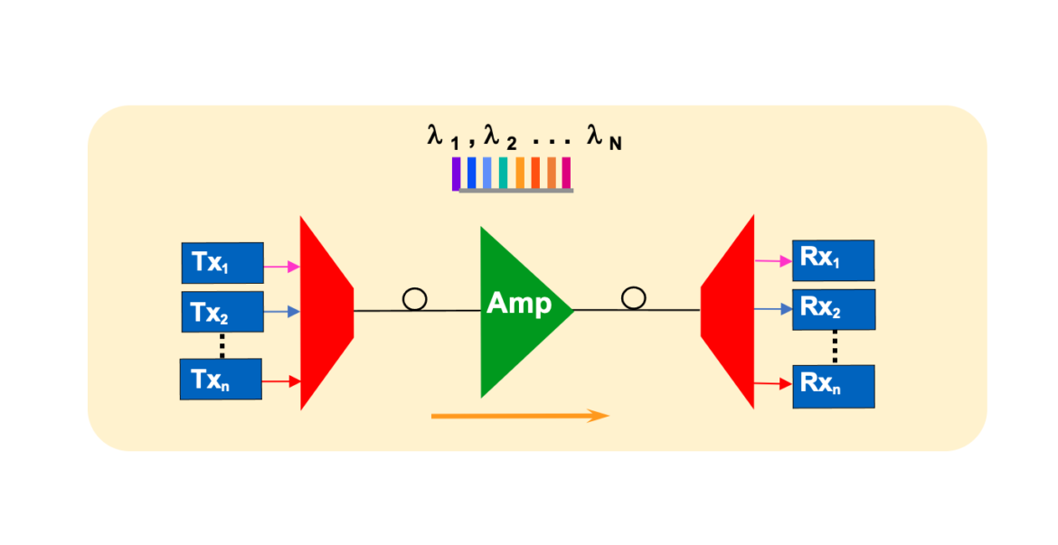
DWDM is based on the principle of multiplexing and demultiplexing different wavelengths of light onto a single optical fiber. The technology uses a combination of optical filters, amplifiers, and multiplexers to combine and separate the different wavelengths of light. The resulting DWDM signal can transmit multiple channels of data over long distances, which makes it ideal for high-capacity networking applications.

Factors to Consider When Designing DWDM Link

Designing a DWDM link requires consideration of several factors, including the wavelength plan, dispersion management, and power budget.

Wavelength Plan

The wavelength plan determines the number of channels that can be transmitted over a single fiber. It involves selecting the wavelengths of light that will be used for the different channels and ensuring that they do not overlap with each other. The selection of the right wavelength plan is crucial for achieving maximum capacity and minimizing signal interference.

Dispersion Management

Dispersion is the tendency of different wavelengths of light to travel at different speeds, causing them to spread out over long distances. Dispersion management involves selecting the right type of fiber and configuring the network to minimize dispersion. This is important to ensure that the signals remain coherent and do not degrade over long distances.

Power Budget

The power budget is the total amount of optical power available for the network. It involves calculating the total losses in the network and ensuring that there is enough optical power to transmit the signals over the desired distance. The power budget is critical to ensuring that the signals are strong enough to overcome any losses in the network.

Amplification Techniques for DWDM Link

Amplification is the process of boosting the strength of the optical signal to ensure that it can travel over long distances. There are several amplification techniques that can be used for DWDM link, including the Erbium-Doped Fiber Amplifier (EDFA), Raman Amplifier, and Semiconductor Optical Amplifier (SOA).

Erbium-Doped Fiber Amplifier (EDFA)

EDFA is the most commonly used amplification technique for DWDM link. It uses a small amount of erbium-doped fiber to amplify the optical signal. EDFA is known for its low noise, high gain, and reliability, making it ideal for long-haul applications.

Raman Amplifier

Raman Amplifier uses a technique called Raman scattering to amplify the optical signal. It is known for its ability to amplify a wide range of wavelengths and its low noise performance. Raman Amplifier is ideal for applications where the signal needs to be amplified over long distances.

Semiconductor Optical Amplifier (SOA)

SOA is a relatively new amplification technique that uses semiconductor materials to amplify the optical signal. It is known for its high-speed amplification and low cost. However, SOA has a higher noise figure and lower gain than EDFA and Raman Amplifier, making it less suitable for long-haul applications.

Designing and Configuring DWDM Network

Designing and configuring a DWDM network involves selecting the right network topology, equipment, and management techniques.

Network Topology

Network topology refers to the physical layout of the network. It involves selecting the right type of fiber, the number of nodes, and the type of interconnection. The selection of the right network topology is crucial for achieving maximum capacity and reliability.

Equipment Selection

Equipment selection involves choosing the right type of equipment for each node in the network. It involves selecting the right type of multiplexer, demultiplexer, amplifier, and transceiver. The selection of the right equipment is crucial for achieving maximum capacity and reliability.

Network Management

Network management involves configuring the network to optimize its performance and reliability. It involves selecting the right type of management software, monitoring the network performance, and performing regular maintenance. The selection of the right network management techniques is crucial for ensuring that the network operates at maximum efficiency.

Maintenance and Troubleshooting

Maintenance and troubleshooting are crucial for ensuring the optimum performance of a DWDM network. Regular maintenance involves cleaning the fiber connections, replacing faulty equipment, and upgrading the software. Troubleshooting involves identifying and resolving any issues that may arise in the network, such as signal loss or interference.

Conclusion

Designing and amplifying a DWDM link is a complex task that requires careful consideration of several factors. The selection of the right wavelength plan, dispersion management, power budget, and amplification technique is crucial for achieving maximum capacity and reliability. In addition, selecting the right network topology, equipment, and management techniques is crucial for ensuring optimum network performance and efficiency.

FAQs

  1. What is DWDM technology? DWDM technology is a high-capacity optical networking technology that enables the transmission of multiple signals over a single fiber by using different wavelengths of light.
  2. What is dispersion management? Dispersion management involves selecting the right type of fiber and configuring the network to minimize dispersion. This is important to ensure that the signals remain coherent and do not degrade over long distances.
  3. What is an Erbium-Doped Fiber Amplifier (EDFA)? EDFA is the most commonly used amplification technique for DWDM link. It uses a small amount of erbium-doped fiber to amplify the optical signal.
  4. What is network topology? Network topology refers to the physical layout of the network. It involves selecting the right type of fiber, the number of nodes, and the type of interconnection.
  5. How can I troubleshoot a DWDM network? Troubleshooting a DWDM network involves identifying and resolving any issues that may arise in the network, such as signal loss or interference. Regular maintenance and monitoring can help prevent issues from occurring.

If you are working in the field of optical networks, it’s important to understand how to calculate Bit Error Rate (BER) for different modulations. BER is the measure of the number of errors in a communication channel. In this article, we will discuss how to calculate BER for different modulations, including binary, M-ary, and coherent modulations, in optical networks.

Introduction to Bit Error Rate (BER)

Before we dive into calculating BER for different modulations, it’s essential to understand what BER is and why it’s important. BER is a measure of the number of errors that occur in a communication channel. It’s used to evaluate the quality of a digital communication system. The lower the BER, the higher the quality of the communication system.

Binary Modulation

Binary modulation is the simplest form of modulation, where a single bit is transmitted over a communication channel. In binary modulation, the bit is either a 0 or a 1. The BER for binary modulation can be calculated using the following equation:

BER = 0.5 * erfc(sqrt(Eb/N0))

where erfc is the complementary error function, Eb is the energy per bit, and N0 is the noise power spectral density.

M-ary Modulation

M-ary modulation is a type of modulation where more than two symbols are transmitted over a communication channel. In M-ary modulation, each symbol represents multiple bits. The BER for M-ary modulation can be calculated using the following equation:

BER = 0.5 * erfc(sqrt(1.5 * log2M * Eb/N0))

where M is the number of symbols used in the modulation.

Coherent Modulation

Coherent modulation is a type of modulation where the carrier signal and the signal being transmitted are in phase. In coherent modulation, the phase of the carrier signal is used to encode the information being transmitted. The BER for coherent modulation can be calculated using the following equation:

BER = 0.5 * erfc(sqrt(Es/N0))

where Es is the energy per symbol.

Example Calculation

Let’s consider an example of calculating BER for binary modulation. Suppose we are transmitting a signal with an energy per bit of 0.01 mJ and a noise power spectral density of 0.1 nW/Hz. Using the equation for binary modulation, we can calculate the BER as follows:

BER = 0.5 * erfc(sqrt(0.01/0.1))

BER = 0.0082

This means that for every 1000 bits transmitted, 8.2 bits will be received in error.

Conclusion

Calculating BER is an essential aspect of designing and evaluating digital communication systems. In optical networks, understanding how to calculate BER for different modulations is crucial. In this article, we discussed how to calculate BER for binary, M-ary, and coherent modulations in optical networks.

FAQs

  1. What is BER? BER is a measure of the number of errors that occur in a communication channel. It’s used to evaluate the quality of a digital communication system.
  2. Why is BER important in optical networks? BER is important in optical networks because it’s used to evaluate the quality of the communication system and ensure that the data being transmitted is received accurately.
  3. What is binary modulation? Binary modulation is the simplest form of modulation, where a single bit is transmitted over a communication channel.
  4. What is M-ary modulation? M-ary modulation is a type of modulation where more than two symbols are transmitted over a communication channel.
  5. What is coherent modulation? Coherent modulation is a type of modulation where the carrier signal and the signal being transmitted are in phase, and the phase of the carrier signal is used to encode the information being transmitted.
  6. How is BER calculated for M-ary modulation? BER for M-ary modulation is calculated using the equation: BER = 0.5 * erfc(sqrt(1.5 * log2M * Eb/N0)), where M is the number of symbols used in the modulation.
  7. What does a low BER value indicate? A low BER value indicates that the digital communication system is of high quality and the data being transmitted is received accurately.
  8. How can BER be reduced? BER can be reduced by increasing the energy per bit, reducing the noise power spectral density, or using more advanced modulation techniques that are less susceptible to noise.
  9. What are some common modulation techniques used in optical networks? Common modulation techniques used in optical networks include Amplitude Shift Keying (ASK), Frequency Shift Keying (FSK), Phase Shift Keying (PSK), and Quadrature Amplitude Modulation (QAM).
  10. Can BER be reduced to zero? No, it is not possible to reduce BER to zero in any communication system. However, by using advanced modulation techniques and error correction codes, BER can be reduced to a very low value, ensuring high-quality digital communication.

RAMAN fiber links are widely used in the telecommunications industry to transmit information over long distances. They are known for their high capacity, low attenuation, and ability to transmit signals over hundreds of kilometers. However, like any other technology, RAMAN fiber links can experience issues that require troubleshooting. In this article, we will discuss the common problems encountered in RAMAN fiber links and how to troubleshoot them effectively.

Understanding RAMAN Fiber Links

Before we delve into troubleshooting, let’s first understand what RAMAN fiber links are. A RAMAN fiber link is a type of optical fiber that uses a phenomenon called Raman scattering to amplify light signals. When a light signal is transmitted through the fiber, some of the photons interact with the atoms in the fiber, causing them to vibrate. This vibration results in the creation of new photons, which have the same wavelength as the original signal but are out of phase with it. This process amplifies the original signal, allowing it to travel further without losing strength.

Common Issues with RAMAN Fiber Links

RAMAN fiber links can experience various issues that affect their performance. These issues include:

Loss of Signal

A loss of signal occurs when the light signal transmitted through the fiber is too weak to be detected by the receiver. This can be caused by attenuation or absorption of the signal along the fiber, or by poor coupling between the fiber and the optical components.

Signal Distortion

Signal distortion occurs when the signal is altered as it travels through the fiber. This can be caused by dispersion, which is the spreading of the signal over time, or by nonlinear effects, such as self-phase modulation and cross-phase modulation.

Signal Reflection

Signal reflection occurs when some of the signal is reflected back towards the source, causing interference with the original signal. This can be caused by poor connections or mismatches between components in the fiber link.

Troubleshooting RAMAN Fiber Links

Now that we have identified the common issues with RAMAN fiber links, let’s look at how to troubleshoot them effectively.

Loss of Signal

To troubleshoot a loss of signal, first, check the power levels at the transmitter and receiver ends of the fiber link. If the power levels are too low, increase them by adjusting the output power of the transmitter or by adding amplifiers to the fiber link. If the power levels are too high, reduce them by adjusting the output power of the transmitter or by attenuating the signal with a fiber attenuator.

If the power levels are within the acceptable range but the signal is still weak, check for attenuation or absorption along the fiber link. Use an optical time-domain reflectometer (OTDR) to measure the attenuation along the fiber link. If there is a high level of attenuation at a particular point, check for breaks or bends in the fiber or for splices that may be causing the attenuation.

Signal Distortion

To troubleshoot signal distortion, first, check for dispersion along the fiber link. Dispersion can be compensated for using dispersion compensation modules, which can be inserted into the fiber link at specific points.

If the signal distortion is caused by nonlinear effects, such as self-phase modulation or cross-phase modulation, use a spectrum analyzer to measure the spectral components of the signal. If the spectral components are broadened, this indicates the presence of nonlinear effects. To reduce nonlinear effects, reduce the power levels at the transmitter or use dispersion-shifted fiber, which is designed to minimize nonlinear effects.

Signal Reflection

To troubleshoot signal reflection, first, check for mismatches or poor connections between components in the fiber link. Ensure that connectors are properly aligned and that there are no gaps between the components. Use a visual fault locator (VFL) to identify any gaps or

scratches on the connector surface that may be causing reflection. Replace or adjust any components that are causing reflection to reduce interference with the signal.

Conclusion

Troubleshooting RAMAN fiber links can be challenging, but by understanding the common issues and following the appropriate steps, you can effectively identify and resolve any problems that arise. Remember to check power levels, attenuation, dispersion, nonlinear effects, and reflection when troubleshooting RAMAN fiber links.

FAQs

  1. What is a RAMAN fiber link? 
    A RAMAN fiber link is a type of optical fiber that uses Raman scattering to amplify light signals.

  2. What causes a loss of signal in RAMAN fiber links?
    A loss of signal can be caused by attenuation or absorption along the fiber or by poor coupling between components in the fiber link.

  3. How can I troubleshoot signal distortion in RAMAN fiber links?
    Signal distortion can be caused by dispersion or nonlinear effects. Use dispersion compensation modules to compensate for dispersion, and reduce power levels or use dispersion-shifted fiber to minimize nonlinear effects.

  4. How can I troubleshoot signal reflection in RAMAN fiber links?
    Signal reflection can be caused by poor connections or mismatches between components in the fiber link. Use a VFL to identify any gaps or scratches on the connector surface that may be causing reflection, and replace or adjust any components that are causing interference with the signal.

  5. What is an OTDR?
    An OTDR is an optical time-domain reflectometer used to measure the attenuation along a fiber link.

  6. Can RAMAN fiber links transmit signals over long distances?
    Yes, RAMAN fiber links are known for their ability to transmit signals over hundreds of kilometers.

  7. How do I know if my RAMAN fiber link is experiencing signal distortion?
    Signal distortion can cause the signal to be altered as it travels through the fiber. This can be identified by using a spectrum analyzer to measure the spectral components of the signal. If the spectral components are broadened, this indicates the presence of nonlinear effects.

  8. What is the best way to reduce signal reflection in a RAMAN fiber link?
    The best way to reduce signal reflection is to ensure that connectors are properly aligned and that there are no gaps between components. Use a VFL to identify any gaps or scratches on the connector surface that may be causing reflection, and replace or adjust any components that are causing interference with the signal.

  9. How can I improve the performance of my RAMAN fiber link?
    You can improve the performance of your RAMAN fiber link by regularly checking power levels, attenuation, dispersion, nonlinear effects, and reflection. Use appropriate troubleshooting techniques to identify and resolve any issues that arise.

  10. What are the advantages of using RAMAN fiber links?
    RAMAN fiber links have several advantages, including high capacity, low attenuation, and the ability to transmit signals over long distances without losing strength. They are widely used in the telecommunications industry to transmit information over large distances.


As data rates continue to increase, high-speed data transmission has become essential in various industries. Coherent optical systems are one of the most popular solutions for high-speed data transmission due to their ability to transmit multiple signals simultaneously. However, when it comes to measuring the performance of these systems, latency becomes a crucial factor to consider. In this article, we will explore what latency is, how it affects coherent optical systems, and how to calculate it.

Understanding Latency

Latency refers to the delay in data transmission between two points. It is the time taken for a data signal to travel from the sender to the receiver. Latency is measured in time units such as milliseconds (ms), microseconds (μs), or nanoseconds (ns).

In coherent optical systems, latency is the time taken for a signal to travel through the system, including the optical fiber and the processing components such as amplifiers, modulators, and demodulators.

Factors Affecting Latency in Coherent Optical Systems

Several factors can affect the latency in coherent optical systems. The following are the most significant ones:

Distance

The distance between the sender and the receiver affects the latency in coherent optical systems. The longer the distance, the higher the latency.

Fiber Type and Quality

The type and quality of the optical fiber used in the system also affect the latency. Single-mode fibers have lower latency than multimode fibers. Additionally, the quality of the fiber can impact the latency due to factors such as signal loss and dispersion.

Amplifiers

Optical amplifiers are used in coherent optical systems to boost the signal strength. However, they can also introduce latency to the system. The type and number of amplifiers used can affect the latency.

Modulation

Modulation is the process of varying the characteristics of a signal to carry information. In coherent optical systems, modulation affects the latency because it takes time to modulate and demodulate the signal.

Processing Components

Processing components such as modulators and demodulators can also introduce latency to the system. The number and type of these components used in the system can affect the latency.

Calculating Latency in Coherent Optical Systems

To calculate the latency in coherent optical systems, the following formula can be used:

Latency (ms) = Distance (km) × Refractive Index × 2

Where Refractive Index is the ratio of the speed of light in a vacuum to the speed of light in the optical fiber.

For example, let’s say we have a coherent optical system with a distance of 500 km and a refractive index of 1.468.

Latency = 500 km × 1.468 × 2 = 1.468 ms

However, this formula only calculates the latency due to the optical fiber. To calculate the total latency of the system, we need to consider the latency introduced by the processing components, amplifiers, and modulation.

Example of Calculating Latency in Coherent Optical Systems

Let’s consider an example to understand how to calculate the total latency in a coherent optical system.

Suppose we have a coherent optical system that uses a single-mode fiber with a length of 100 km. The system has two amplifiers, and the modulator and demodulator introduce a latency of 0.5 ms each. The refractive index of the fiber is 1.468.

Using the formula mentioned above, we can calculate the latency due to the fiber:

Latency (ms) = Distance (km) × Refractive Index × 2

= 100 km × 1.468 × 2

The latency due to the fiber is 293.6 μs or 0.2936 ms.

To calculate the total latency, we need to add the latency introduced by the amplifiers, modulator, and demodulator.

Total Latency (ms) = Latency due to Fiber (ms) + Latency due to Amplifiers (ms) + Latency due to Modulation (ms)

Latency due to Amplifiers (ms) = Number of Amplifiers × Amplifier Latency (ms)

Latency due to Modulation (ms) = Modulator Latency (ms) + Demodulator Latency (ms)

In our example, the latency due to amplifiers is:

Latency due to Amplifiers (ms) = 2 × 0.1 ms = 0.2 ms

The latency due to modulation is:

Latency due to Modulation (ms) = 0.5 ms + 0.5 ms = 1 ms

Therefore, the total latency in our example is:

Total Latency (ms) = 0.2936 ms + 0.2 ms + 1 ms = 1.4936 ms

Conclusion

Latency is an important factor to consider when designing and testing coherent optical systems. It affects the performance of the system and can limit the data transmission rate. Understanding the factors that affect latency and how to calculate it is crucial for ensuring the system meets the required performance metrics.

FAQs

  1. What is the maximum acceptable latency in coherent optical systems?
  • The maximum acceptable latency depends on the specific application and performance requirements.
  1. Can latency be reduced in coherent optical systems?
  • Yes, latency can be reduced by using high-quality fiber, minimizing the number of processing components, and optimizing the system design.
  1. Does latency affect the signal quality in coherent optical systems?
  • Yes, high latency can lead to signal distortion and affect the signal quality.
  1. What is the difference between latency and jitter in coherent optical systems?
  • Latency refers to the delay in data transmission, while jitter refers to the variation in the delay.
  1. Is latency the only factor affecting the performance of coherent optical systems?
  • No, other factors such as signal-to-noise ratio, chromatic dispersion, and polarization mode dispersion can also affect the performance of coherent optical systems.
    1. Can latency be measured in real-time in coherent optical systems?
    • Yes, latency can be measured in real-time using specialized instruments such as optical time-domain reflectometers (OTDRs) and optical spectrum analyzers (OSAs).
    1. How can latency affect the data transmission rate in coherent optical systems?
    • High latency can limit the data transmission rate by increasing the time taken for signals to travel through the system.
    1. Are there any industry standards for latency in coherent optical systems?
    • Yes, various industry standards such as ITU-T G.709 define the maximum acceptable latency for coherent optical systems.
    1. What are some common techniques used to reduce latency in coherent optical systems?
    • Techniques such as forward error correction (FEC), coherent detection, and wavelength-division multiplexing (WDM) can be used to reduce latency in coherent optical systems.
    1. How important is latency in coherent optical systems for applications such as 5G and cloud computing?
    • Latency is crucial in applications such as 5G and cloud computing, where high-speed data transmission and low latency are essential for ensuring reliable and efficient operations.

OTN (Optical Transport Network) is a network that is responsible for transmitting high-speed data over long distances. It is widely used in telecommunication systems to provide reliable and high-quality communication services. However, like any other system, OTN can also face issues that may cause alarms. These alarms indicate the faults in the network and may cause interruptions in communication services. Therefore, it is crucial to understand the causes of these alarms and how to troubleshoot them. In this article, we will discuss OTN alarms and their troubleshooting steps.

Table of Contents

  1. Introduction
  2. What is OTN Alarm?
  3. Types of OTN Alarms
    • 3.1 Loss of Signal (LOS)
    • 3.2 Loss of Frame (LOF)
    • 3.3 Loss of Multi-Frame Alignment (LOMFA)
    • 3.4 Loss of Frame Alignment (LOFA)
  4. Troubleshooting Steps for OTN Alarms
    • 4.1 Inspect the Fiber Cable
    • 4.2 Check the Power Levels
    • 4.3 Verify the Connection Points
    • 4.4 Verify the Network Settings
    • 4.5 Upgrade the Firmware
    • 4.6 Consult with Technical Support
  5. Conclusion
  6. FAQs

What is OTN Alarm?

An OTN alarm is a notification that indicates the occurrence of an error in the network. These alarms are raised when the network equipment detects a fault in the transmission, reception, or processing of the signals. OTN alarms can affect the network’s performance and cause service interruptions, making it essential to detect and troubleshoot them promptly.

Types of OTN Alarms

There are various types of OTN alarms, which include:

Loss of Signal (LOS)

LOS occurs when the OTN equipment fails to detect the optical signal coming from the previous equipment. This can be due to a faulty fiber connection, equipment failure, or optical attenuation.

Loss of Frame (LOF)

LOF is an alarm that indicates that the equipment cannot detect the frame structure of the received signal. It can be due to errors in the synchronization or configuration of the equipment.

Loss of Multi-Frame Alignment (LOMFA)

LOMFA is an alarm that indicates that the received signal’s multi-frame structure is lost. It can be due to equipment failure or errors in the configuration of the equipment.

Loss of Frame Alignment (LOFA)

LOFA is an alarm that indicates that the received signal’s frame alignment is lost. It can be due to equipment failure or errors in the configuration of the equipment.

Troubleshooting Steps for OTN Alarms

Troubleshooting OTN alarms can be a complex process that requires technical expertise. Here are some general troubleshooting steps that can be followed to detect and troubleshoot OTN alarms:

Inspect the Fiber Cable

One of the common causes of OTN alarms is a faulty fiber cable. Inspecting the fiber cable can help identify any damage, cuts, or bends that may be affecting the signal transmission. If any issues are detected, the fiber cable needs to be replaced.

Check the Power Levels

Low power levels can cause OTN alarms, which can be due to faulty equipment or damaged cables. Checking the power levels can help identify the cause of the alarm, and corrective actions can be taken accordingly.

Verify the Connection Points

OTN equipment is connected to the network through various connection points, such as connectors, splices, or patch panels. A loose or damaged connection can cause alarms, so verifying the connection

Verify the Network Settings

OTN equipment settings can impact the network’s performance, and incorrect settings can cause alarms. Verifying the network settings can help identify any incorrect settings and make the necessary changes.

Upgrade the Firmware

An outdated or faulty firmware can also cause OTN alarms. Upgrading the firmware to the latest version can help resolve the issues and improve the network’s performance.

Consult with Technical Support

If the OTN alarms persist even after performing the above steps, it is advisable to contact technical support. They have the expertise and tools to diagnose and troubleshoot complex issues.

Conclusion

OTN alarms can impact the network’s performance and cause service interruptions, making it crucial to detect and troubleshoot them promptly. By understanding the causes of OTN alarms and following the troubleshooting steps, network administrators can ensure the smooth operation of the network.

FAQs

  1. What is OTN, and how does it work? OTN is a network that is responsible for transmitting high-speed data over long distances. It works by using optical signals to transmit data through fiber-optic cables.
  2. What are the common causes of OTN alarms? The common causes of OTN alarms include faulty fiber cables, low power levels, incorrect network settings, and outdated or faulty firmware.
  3. How can I troubleshoot OTN alarms? Troubleshooting OTN alarms can involve inspecting the fiber cable, checking the power levels, verifying the connection points, verifying the network settings, upgrading the firmware, and consulting technical support.
  4. Can OTN alarms be prevented? OTN alarms cannot be prevented entirely, but regular maintenance, monitoring, and upgrading can reduce their occurrence.
  5. How can I ensure the smooth operation of the OTN network? To ensure the smooth operation of the OTN network, it is essential to perform regular maintenance, monitoring, and upgrading. Additionally, having a robust disaster recovery plan can help minimize downtime and service interruptions.
    1. What is the impact of OTN alarms on network performance? OTN alarms can significantly impact network performance and cause service interruptions. The alarms indicate faults in the network and may require prompt troubleshooting to prevent downtime.
    2. How often should I perform maintenance on the OTN network? Regular maintenance should be performed on the OTN network to ensure its smooth operation. The frequency of maintenance can vary depending on the network’s complexity and usage, but it is advisable to perform maintenance at least once every six months.
    3. What should I do if I detect an OTN alarm? If you detect an OTN alarm, you should immediately start troubleshooting using the steps outlined in this article. If you are unable to resolve the issue, contact technical support for assistance.
    1. Can I troubleshoot OTN alarms without technical expertise? Troubleshooting OTN alarms can be a complex process that requires technical expertise. If you do not have the necessary technical knowledge, it is advisable to contact technical support for assistance.
    2. How important is it to address OTN alarms promptly? Addressing OTN alarms promptly is crucial as they can impact network performance and cause service interruptions. Delayed or ignored alarms can lead to extended downtime, affecting the organization’s productivity and reputation.

Discover the most effective OSNR improvement techniques to boost the quality and reliability of optical communication systems. Learn the basics, benefits, and practical applications of OSNR improvement techniques today!

Introduction:

Optical signal-to-noise ratio (OSNR) is a key performance parameter that measures the quality of an optical communication system. It is a critical factor that determines the capacity, reliability, and stability of optical networks. To ensure optimal OSNR performance, various OSNR improvement techniques have been developed and implemented in modern optical communication systems.

In this article, we will delve deeper into the world of OSNR improvement techniques and explore the most effective ways to boost OSNR and enhance the quality of optical communication systems. From basic concepts to practical applications, we will cover everything you need to know about OSNR improvement techniques and how they can benefit your business.

So, let’s get started!

OSNR Improvement Techniques: Basics and Benefits

What is OSNR, and Why Does it Matter?

OSNR is a measure of the signal quality of an optical communication system, which compares the power of the signal to the power of the noise in the system. In simple terms, it is a ratio of the signal power to the noise power. A higher OSNR indicates a better signal quality and a lower error rate, while a lower OSNR indicates a weaker signal and a higher error rate.

OSNR is a critical factor that determines the performance and reliability of optical communication systems. It affects the capacity, reach, and stability of the system, as well as the cost and complexity of the equipment. Therefore, maintaining optimal OSNR is essential for ensuring high-quality and efficient optical communication.

What are OSNR Improvement Techniques?

OSNR improvement techniques are a set of methods and technologies used to enhance the OSNR performance of optical communication systems. They aim to reduce the noise level in the system and increase the signal-to-noise ratio, thereby improving the quality and reliability of the system.

There are various OSNR improvement techniques available today, ranging from simple adjustments to advanced technologies. Some of the most common techniques include:

  1. Optical Amplification: This technique involves amplifying the optical signal to increase its power and improve its quality. It can be done using various types of amplifiers, such as erbium-doped fiber amplifiers (EDFAs), Raman amplifiers, and semiconductor optical amplifiers (SOAs).
  2. Dispersion Management: This technique involves managing the dispersion properties of the optical fiber to minimize the pulse spreading and reduce the noise in the system. It can be done using various dispersion compensation techniques, such as dispersion-compensating fibers (DCFs), dispersion-shifted fibers (DSFs), and chirped fiber Bragg gratings (CFBGs).
  3. Polarization Management: This technique involves managing the polarization properties of the optical signal to minimize the polarization-mode dispersion (PMD) and reduce the noise in the system. It can be done using various polarization-management techniques, such as polarization-maintaining fibers (PMFs), polarization controllers, and polarization splitters.
  4. Wavelength Management: This technique involves managing the wavelength properties of the optical signal to minimize the impact of wavelength-dependent losses and reduce the noise in the system. It can be done using various wavelength-management techniques, such as wavelength-division multiplexing (WDM), coarse wavelength-division multiplexing (CWDM), and dense wavelength-division multiplexing (DWDM).

What are the Benefits of OSNR Improvement Techniques?

OSNR improvement techniques offer numerous benefits for optical communication systems, including:

  1. Improved Signal Quality: OSNR improvement techniques can significantly improve the signal quality ofthe system, leading to a higher data transmission rate and a lower error rate.
    1. Increased System Reach: OSNR improvement techniques can extend the reach of the system by reducing the impact of noise and distortion on the signal.
    2. Enhanced System Stability: OSNR improvement techniques can improve the stability and reliability of the system by reducing the impact of environmental factors and system fluctuations on the signal.
    3. Reduced Cost and Complexity: OSNR improvement techniques can reduce the cost and complexity of the system by allowing the use of lower-power components and simpler architectures.

    Implementing OSNR Improvement Techniques: Best Practices

    Assessing OSNR Performance

    Before implementing OSNR improvement techniques, it is essential to assess the current OSNR performance of the system. This can be done using various OSNR measurement techniques, such as the optical spectrum analyzer (OSA), the optical time-domain reflectometer (OTDR), and the bit-error-rate tester (BERT).

    By analyzing the OSNR performance of the system, you can identify the areas that require improvement and determine the most appropriate OSNR improvement techniques to use.

    Selecting OSNR Improvement Techniques

    When selecting OSNR improvement techniques, it is essential to consider the specific requirements and limitations of the system. Some factors to consider include:

    1. System Type and Configuration: The OSNR improvement techniques used may vary depending on the type and configuration of the system, such as the transmission distance, data rate, and modulation format.
    2. Budget and Resources: The cost and availability of the OSNR improvement techniques may also affect the selection process.
    3. Compatibility and Interoperability: The OSNR improvement techniques used must be compatible with the existing system components and interoperable with other systems.
    4. Performance Requirements: The OSNR improvement techniques used must meet the performance requirements of the system, such as the minimum OSNR level and the maximum error rate.

    Implementing OSNR Improvement Techniques

    Once you have selected the most appropriate OSNR improvement techniques, it is time to implement them into the system. This may involve various steps, such as:

    1. Upgrading or Replacing Equipment: This may involve replacing or upgrading components such as amplifiers, filters, and fibers to improve the OSNR performance of the system.
    2. Optimizing System Settings: This may involve adjusting the system settings, such as the gain, the dispersion compensation, and the polarization control, to optimize the OSNR performance of the system.
    3. Testing and Validation: This may involve testing and validating the OSNR performance of the system after implementing the OSNR improvement techniques to ensure that the desired improvements have been achieved.

    FAQs About OSNR Improvement Techniques

    What is the minimum OSNR level required for optical communication systems?

    The minimum OSNR level required for optical communication systems may vary depending on the specific requirements of the system, such as the data rate, the transmission distance, and the modulation format. Generally, a minimum OSNR level of 20 dB is considered acceptable for most systems.

    How can OSNR improvement techniques affect the cost of optical communication systems?

    OSNR improvement techniques can affect the cost of optical communication systems by allowing the use of lower-power components and simpler architectures, thereby reducing the overall cost and complexity of the system.

    What are the most effective OSNR improvement techniques for long-distance optical communication?

    The most effective OSNR improvement techniques for long-distance optical communication may vary depending on the specific requirements and limitations of the system. Generally, dispersion compensation techniques, such as dispersion-compensating fibers (DCFs), and amplification techniques, such as erbium-doped fiber amplifiers (EDFAs), are effective for improving OSNR in long

    distance optical communication.

    Can OSNR improvement techniques be used in conjunction with other signal quality enhancement techniques?

    Yes, OSNR improvement techniques can be used in conjunction with other signal quality enhancement techniques, such as forward error correction (FEC), modulation schemes, and equalization techniques, to further improve the overall signal quality and reliability of the system.

    Conclusion

    OSNR improvement techniques are essential for ensuring high-quality and reliable optical communication systems. By understanding the basics, benefits, and best practices of OSNR improvement techniques, you can optimize the performance and efficiency of your system and stay ahead of the competition.

    Remember to assess the current OSNR performance of your system, select the most appropriate OSNR improvement techniques based on your specific requirements, and implement them into the system carefully and systematically. With the right OSNR improvement techniques, you can unlock the full potential of your optical communication system and achieve greater success in your business.

    So, what are you waiting for? Start exploring the world of OSNR improvement techniques today and experience the power of high-quality optical communication!

Discover the best Q-factor improvement techniques for optical networks with this comprehensive guide. Learn how to optimize your network’s performance and achieve faster, more reliable connections.

Introduction:

In today’s world, we rely heavily on the internet for everything from work to leisure. Whether it’s streaming videos or conducting business transactions, we need fast and reliable connections. However, with so much data being transmitted over optical networks, maintaining high signal quality can be a challenge. This is where the Q-factor comes into play.

The Q-factor is a metric used to measure the quality of a signal transmitted over an optical network. It takes into account various factors, such as noise, distortion, and attenuation, that can degrade signal quality. A higher Q-factor indicates better signal quality, which translates to faster and more reliable connections.

In this article, we will explore effective Q-factor improvement techniques for optical networks. We will cover everything from signal amplification to dispersion management, and provide tips for optimizing your network’s performance.

  1. Amplification Techniques
  2. Dispersion Management
  3. Polarization Mode Dispersion (PMD) Compensation
  4. Nonlinear Effects Mitigation
  5. Fiber Cleaning and Maintenance

Amplification Techniques:

Optical amplifiers are devices that amplify optical signals without converting them to electrical signals. There are several types of optical amplifiers, including erbium-doped fiber amplifiers (EDFAs), semiconductor optical amplifiers (SOAs), and Raman amplifiers.

EDFAs are the most commonly used optical amplifiers. They work by using an erbium-doped fiber to amplify the signal. EDFAs have a high gain and low noise figure, making them ideal for long-haul optical networks.

SOAs are semiconductor devices that use a gain medium to amplify the signal. They have a much smaller footprint than EDFAs and can be integrated into other optical components, such as modulators and receivers.

Raman amplifiers use a process called stimulated Raman scattering to amplify the signal. They are typically used in conjunction with EDFAs to boost the signal even further.

Dispersion Management:

Dispersion is a phenomenon that occurs when different wavelengths of light travel at different speeds in an optical fiber. This can cause distortion and degradation of the signal, resulting in a lower Q-factor.

There are several techniques for managing dispersion, including:

  • Dispersion compensation fibers: These are fibers designed to compensate for dispersion by introducing an opposite dispersion effect.
  • Dispersion compensation modules: These are devices that use a combination of fibers and other components to manage dispersion.
  • Dispersion-shifted fibers: These fibers are designed to minimize dispersion by shifting the zero-dispersion wavelength to a higher frequency.

Polarization Mode Dispersion (PMD) Compensation:

Polarization mode dispersion is a phenomenon that occurs when different polarization states of light travel at different speeds in an optical fiber. This can cause distortion and degradation of the signal, resulting in a lower Q-factor.

PMD compensation techniques include:

  • PMD compensators: These are devices that use a combination of wave plates and fibers to compensate for PMD.
  • Polarization scramblers: These are devices that randomly change the polarization state of the signal to reduce the impact of PMD.

Nonlinear Effects Mitigation:

Nonlinear effects can occur when the optical signal is too strong, causing distortion and degradation of the signal. These effects can be mitigated using several techniques, including:

  • Dispersion management techniques: As mentioned earlier, dispersion management can help reduce the impact of nonlinear effects.
  • Nonlinear compensation: This involves using specialized components, such as nonlinear optical loops, to compensate for nonlinear effects.
  • Modulation formats: Different modulation formats,such as quadrature amplitude modulation (QAM) and coherent detection, can also help mitigate nonlinear effects.

    Fiber Cleaning and Maintenance:

    Dirty or damaged fibers can also affect signal quality and lower the Q-factor. Regular cleaning and maintenance of the fibers can help prevent these issues. Here are some tips for fiber cleaning and maintenance:

    • Use proper cleaning tools and materials, such as lint-free wipes and isopropyl alcohol.
    • Inspect the fibers regularly for signs of damage, such as bends or breaks.
    • Use protective sleeves or connectors to prevent damage to the fiber ends.
    • Follow the manufacturer’s recommended maintenance schedule for your network components.

    FAQs:

    1. What is the Q-factor in optical networks?

    The Q-factor is a metric used to measure the quality of a signal transmitted over an optical network. It takes into account various factors, such as noise, distortion, and attenuation, that can degrade signal quality. A higher Q-factor indicates better signal quality, which translates to faster and more reliable connections.

    1. What are some effective Q-factor improvement techniques for optical networks?

    Some effective Q-factor improvement techniques for optical networks include signal amplification, dispersion management, PMD compensation, nonlinear effects mitigation, and fiber cleaning and maintenance.

    1. What is dispersion in optical fibers?

    Dispersion is a phenomenon that occurs when different wavelengths of light travel at different speeds in an optical fiber. This can cause distortion and degradation of the signal, resulting in a lower Q-factor.

    Conclusion:

    Achieving a high Q-factor is essential for maintaining fast and reliable connections over optical networks. By implementing effective Q-factor improvement techniques, such as signal amplification, dispersion management, PMD compensation, nonlinear effects mitigation, and fiber cleaning and maintenance, you can optimize your network’s performance and ensure that it meets the demands of today’s data-driven world.

  • With these techniques in mind, you can improve your network’s Q-factor and provide your users with faster, more reliable connections. Remember to regularly inspect and maintain your network components to ensure optimal performance. By doing so, you can keep up with the ever-increasing demands for high-speed data transmission and stay ahead of the competition.In conclusion, Q-factor improvement techniques for optical networks are crucial for maintaining high signal quality and achieving faster, more reliable connections. By implementing these techniques, you can optimize your network’s performance and meet the demands of today’s data-driven world. Keep in mind that regular maintenance and inspection of your network components are key to ensuring optimal performance. With the right tools and techniques, you can boost your network’s Q-factor and provide your users with the best possible experience.

With the increasing demand for high-speed internet and data transmission, optical networks have become an integral part of our daily lives. Optical networks use light to transmit data over long distances, which makes them ideal for transmitting large amounts of data quickly and efficiently. However, one of the challenges of optical networks is to maintain the quality of the transmitted signal, which is measured by the Q-factor. In this article, we will explore Q-factor and the different techniques used to improve it in optical networks.

Table of Contents

  1. What is Q-factor?
  2. Factors affecting Q-factor in optical networks
    1. Optical dispersion
    2. Noise
    3. Attenuation
  3. Techniques to improve Q-factor in optical networks
    1. Forward error correction (FEC)
    2. Optical amplifiers
    3. Dispersion compensation
    4. Polarization mode dispersion compensation
    5. Nonlinear effects mitigation
    6. Regeneration
    7. Optical signal-to-noise ratio (OSNR) optimization
    8. Optical signal shaping
    9. Modulation formats optimization
    10. Use of advanced modulation formats
    11. Use of coherent detection
    12. Use of optical filters
    13. Use of optical fiber designs
  4. Conclusion
  5. FAQs

What is Q-factor?

Q-factor is a measure of the quality of the optical signal transmitted over an optical network. It is a ratio of the signal power to the noise power and is expressed in decibels (dB). A high Q-factor indicates a high-quality signal with low distortion and low noise, while a low Q-factor indicates a poor quality signal with high distortion and high noise.

Factors affecting Q-factor in optical networks

Several factors can affect the Q-factor in optical networks, including:

Optical dispersion

Optical dispersion is the phenomenon where different wavelengths of light travel at different speeds through an optical fiber. This can lead to a broadening of the optical pulse, which can reduce the Q-factor of the transmitted signal.

Noise

Noise is an unwanted signal that can affect the Q-factor of the transmitted signal. There are several sources of noise in optical networks, including thermal noise, amplified spontaneous emission (ASE) noise, and inter-symbol interference (ISI) noise.

Attenuation

Attenuation is the loss of signal power as the signal travels through an optical fiber. This can lead to a reduction in the Q-factor of the transmitted signal.

Techniques to improve Q-factor in optical networks

Several techniques can be used to improve the Q-factor in optical networks. These techniques include:

Forward error correction (FEC)

FEC is a technique that adds redundant data to the transmitted signal, which can be used to correct errors that may occur during transmission. This can improve the Q-factor of the transmitted signal.

Optical amplifiers

Optical amplifiers are devices that amplify the optical signal as it travels through the optical fiber. This can help to compensate for the attenuation of the signal and improve the Q-factor of the transmitted signal.

Dispersion compensation

Dispersion compensation is the process of correcting for the dispersion of the optical signal as it travels through the optical fiber. This can help to reduce the broadening of the optical pulse and improve the Q-factor of the transmitted signal.

Polarization mode dispersion compensation

Polarization mode dispersion (PMD) is the phenomenon where the polarization of the optical signal changes as it travels through the optical fiber. PMD can lead to a reduction in the Q-factor of the transmitted signal. PMD compensation techniques can be used to correct for this and improve the Q-factor of the

Nonlinear effects mitigation

Nonlinear effects can occur in optical networks when the signal power is too high. This can lead to distortions in the optical signal and a reduction in the Q-factor of the transmitted signal. Nonlinear effects mitigation techniques can be used to reduce the impact of nonlinear effects and improve the Q-factor of the transmitted signal.

Regeneration

Regeneration is the process of re-amplifying and reshaping the optical signal at intermediate points along the optical network. This can help to compensate for the attenuation of the signal and improve the Q-factor of the transmitted signal.

Optical signal-to-noise ratio (OSNR) optimization

OSNR is a measure of the ratio of the signal power to the noise power in the optical signal. OSNR optimization techniques can be used to improve the OSNR of the transmitted signal, which can improve the Q-factor of the transmitted signal.

Optical signal shaping

Optical signal shaping techniques can be used to shape the optical signal to reduce the impact of dispersion and improve the Q-factor of the transmitted signal.

Modulation formats optimization

Modulation formats are the ways in which data is encoded onto the optical signal. Modulation formats optimization techniques can be used to optimize the modulation format to improve the Qfactor of the transmitted signal.

Use of advanced modulation formats

Advanced modulation formats, such as quadrature amplitude modulation (QAM), can be used to improve the Q-factor of the transmitted signal.

Use of coherent detection

Coherent detection is a technique that uses a local oscillator to detect the phase and amplitude of the optical signal. Coherent detection can be used to improve the Q-factor of the transmitted signal.

Use of optical filters

Optical filters can be used to filter out unwanted signals and noise in the optical signal. This can improve the Q-factor of the transmitted signal.

Use of optical fiber designs

Different types of optical fiber designs, such as dispersion-shifted fiber (DSF) and non-zero dispersion-shifted fiber (NZDSF), can be used to improve the Qfactor of the transmitted signal.

Conclusion

Q-factor is an important measure of the quality of the transmitted signal in optical networks. There are several factors that can affect the Q-factor, including optical dispersion, noise, and attenuation. However, there are also several techniques that can be used to improve the Q-factor, including FEC, optical amplifiers, dispersion compensation, and polarization mode dispersion compensation. By using a combination of these techniques, it is possible to achieve high Qfactors and high-quality optical signals in optical networks.

FAQ

  1. What is the difference between Q-factor and SNR?

Q-factor and signal-to-noise ratio (SNR) are both measures of the quality of the transmitted signal. However, Q-factor takes into account the effect of noise and distortion on the signal, whereas SNR only measures the ratio of signal power to noise power.

  1. What is the maximum Q-factor that can be achieved in optical networks?

The maximum Q-factor that can be achieved in optical networks depends on several factors, such as the length of the optical fiber, the signal power, and the modulation format used. However, Q-factors in the range of 8-15 dB are commonly achieved in practical optical networks.

  1. What is the role of optical amplifiers in improving Q-factor?

Optical amplifiers can be used to compensate for the attenuation of the optical signal as it travels through the optical fiber. By boosting the signal power, optical amplifiers can improve the Q-factor of the transmitted signal.

  1. Can Q-factor be improved without using regeneration?

Yes, Q-factor can be improved without using regeneration. Techniques such as FEC, optical amplifiers, dispersion compensation, and polarization mode dispersion compensation can all be used to improve the Qfactor of the transmitted signal without the need for regeneration.

  1. How does nonlinear effects mitigation improve Qfactor?

Nonlinear effects can cause distortions in the optical signal, which can reduce the Qfactor of the transmitted signal. Nonlinear effects mitigation techniques, such as nonlinear compensation, can be used to reduce the impact of nonlinear effects and improve the Qfactor of the transmitted signal.

When it comes to optical networks, there are two key concepts that are often confused – bit rate and baud rate. While both concepts are related to data transmission, they have different meanings and applications. In this article, we’ll explore the differences between bit rate and baud rate, their applications in optical networks, and the factors that affect their performance.

Table of Contents

  • Introduction
  • What is Bit Rate?
  • What is Baud Rate?
  • Bit Rate vs. Baud Rate: What’s the Difference?
  • Applications of Bit Rate and Baud Rate in Optical Networks
  • Factors Affecting Bit Rate and Baud Rate Performance in Optical Networks
  • How to Measure Bit Rate and Baud Rate in Optical Networks
  • The Importance of Choosing the Right Bit Rate and Baud Rate in Optical Networks
  • Challenges in Bit Rate and Baud Rate Management in Optical Networks
  • Future Trends in Bit Rate and Baud Rate in Optical Networks
  • Conclusion
  • FAQs

Introduction

Optical networks are used to transmit data over long distances using light. These networks have become increasingly popular due to their high bandwidth and low latency. However, managing the transmission of data in an optical network requires an understanding of key concepts like bit rate and baud rate. In this article, we’ll explain these concepts and their significance in optical network performance.

What is Bit Rate?

Bit rate refers to the number of bits that can be transmitted over a communication channel per unit of time. In other words, it is the amount of data that can be transmitted in a given time interval. Bit rate is measured in bits per second (bps) and is an important metric for measuring the performance of a communication channel. The higher the bit rate, the faster data can be transmitted.

What is Baud Rate?

Baud rate, on the other hand, refers to the number of signal changes that occur per second in a communication channel. This is also known as the symbol rate, as each signal change represents a symbol that can represent multiple bits. Baud rate is measured in symbols per second (sps) and is a critical factor in determining the maximum bit rate that can be transmitted over a communication channel.

Bit Rate vs. Baud Rate: What’s the Difference?

While bit rate and baud rate are related, they have different meanings and applications. Bit rate measures the amount of data that can be transmitted over a communication channel, while baud rate measures the number of signal changes that occur in the channel per second. In other words, the bit rate is the number of bits transmitted per unit time, while the baud rate is the number of symbols transmitted per unit time.

It’s important to note that the bit rate and baud rate are not always equal. This is because one symbol can represent multiple bits. For example, in a 16-QAM (Quadrature Amplitude Modulation) system, one symbol can represent four bits. In this case, the bit rate is four times the baud rate.

Applications of Bit Rate and Baud Rate in Optical Networks

In optical networks, bit rate and baud rate are critical factors in determining the maximum amount of data that can be transmitted. Optical networks use various modulation techniques, such as Amplitude Shift Keying (ASK), Frequency Shift Keying (FSK), and Phase Shift Keying (PSK), to encode data onto light signals. The bit rate and baud rate determine the maximum number of symbols that can be transmitted per second, which in turn determines the maximum bit rate.

Factors Affecting Bit Rate and Baud Rate Performance in Optical Networks

Several factors can affect the performance of bit rate and baud rate in optical networks. These include:

  • Transmission distance: The longer the transmission distance,the lower the bit rate and baud rate due to signal attenuation and dispersion.
    • Optical power: Higher optical power allows for higher bit rates, but can also cause signal distortion and noise.
    • Fiber type: Different types of fiber have different attenuation and dispersion characteristics that affect the bit rate and baud rate.
    • Modulation technique: Different modulation techniques have different performance tradeoffs in terms of bit rate and baud rate.
    • Channel bandwidth: The bandwidth of the communication channel affects the maximum bit rate that can be transmitted.

    Optimizing these factors can lead to better bit rate and baud rate performance in optical networks.

    How to Measure Bit Rate and Baud Rate in Optical Networks

    Measuring the bit rate and baud rate in an optical network requires specialized test equipment such as a bit error rate tester (BERT) or an optical spectrum analyzer (OSA). These tools can measure the signal quality and distortion in the communication channel to determine the maximum bit rate and baud rate that can be achieved.

    The Importance of Choosing the Right Bit Rate and Baud Rate in Optical Networks

    Choosing the right bit rate and baud rate is critical for optimizing the performance of an optical network. Too high a bit rate or baud rate can lead to signal distortion, while too low a bit rate or baud rate can limit the amount of data that can be transmitted. By carefully choosing the optimal bit rate and baud rate based on the specific application requirements and channel characteristics, the performance of an optical network can be optimized.

    Challenges in Bit Rate and Baud Rate Management in Optical Networks

    Managing bit rate and baud rate in optical networks can be challenging due to the many factors that affect their performance. In addition, the rapid growth of data traffic and the need for higher bandwidth in optical networks require constant innovation and optimization of bit rate and baud rate management techniques.

    Future Trends in Bit Rate and Baud Rate in Optical Networks

    The future of bit rate and baud rate in optical networks is promising, with many new technologies and techniques being developed to improve their performance. These include advanced modulation techniques, such as higher-order modulation, and new fiber types with improved attenuation and dispersion characteristics. Additionally, machine learning and artificial intelligence are being used to optimize bit rate and baud rate management in optical networks.

    Conclusion

    Bit rate and baud rate are critical concepts in optical networks that determine the maximum amount of data that can be transmitted. While related, they have different meanings and applications. Optimizing the performance of bit rate and baud rate in optical networks requires careful consideration of many factors, including transmission distance, optical power, fiber type, modulation technique, and channel bandwidth. By choosing the right bit rate and baud rate and utilizing advanced technologies, the performance of optical networks can be optimized to meet the growing demand for high-bandwidth data transmission.

    FAQs

    1. What is the difference between bit rate and baud rate?
    • Bit rate measures the amount of data that can be transmitted over a communication channel, while baud rate measures the number of signal changes that occur per second in the channel.
    1. What is the importance of choosing the right bit rate and baud rate in optical networks?
    • Choosing the right bit rate and baud rate is critical for optimizing the performance of an optical network. Too high a bit rate or baud rate can lead to signal distortion, while too low a bit rate or baud rate can limit the amount of data that can be transmitted.
    1. What factors affect bit rate and baud rate performance in optical networks?
    • Factors that affect bit rate and baud rate performance in optical networks include transmission distance, optical power, fiber type, modulation technique, and channel bandwidth.
    1. How can bit rate and baud rate be measured in optical networks?
    • Bit rate and baud rate in optical networks can be measuredusing specialized test equipment such as a bit error rate tester (BERT) or an optical spectrum analyzer (OSA).
      1. What are some future trends in bit rate and baud rate in optical networks?
      • Future trends in bit rate and baud rate in optical networks include advanced modulation techniques, new fiber types with improved attenuation and dispersion characteristics, and the use of machine learning and artificial intelligence to optimize bit rate and baud rate management.
        1. Can bit rate and baud rate be equal?
        • Yes, bit rate and baud rate can be equal, but this is not always the case. One symbol can represent multiple bits, so the bit rate can be higher than the baud rate.
        1. What is the maximum bit rate that can be transmitted over an optical network?
        • The maximum bit rate that can be transmitted over an optical network depends on several factors, including the modulation technique, channel bandwidth, and transmission distance. The use of advanced modulation techniques and optimization of other factors can lead to higher bit rates.
        1. How do bit rate and baud rate affect the performance of an optical network?
        • Bit rate and baud rate are critical factors in determining the maximum amount of data that can be transmitted over an optical network. Choosing the right bit rate and baud rate and optimizing their performance can lead to better data transmission and network performance.
          1. What are some common modulation techniques used in optical networks?
          • Some common modulation techniques used in optical networks include Amplitude Shift Keying (ASK), Frequency Shift Keying (FSK), and Phase Shift Keying (PSK).
          1. What is the role of machine learning and artificial intelligence in optimizing bit rate and baud rate management?
          • Machine learning and artificial intelligence can be used to analyze and optimize various factors that affect bit rate and baud rate performance in optical networks, such as transmission distance, optical power, fiber type, and modulation technique. By leveraging advanced algorithms and predictive analytics, these technologies can improve network performance and efficiency.

As data traffic continues to grow exponentially, Optical Transport Networks (OTN) have become the backbone of modern communication networks. OTN offers high-speed, reliable, and scalable communication services, enabling the efficient transport of large volumes of data over long distances. In OTN, Bit Error Rate (BER) is one of the key parameters used to measure the quality of data transmission. However, different error rates such as BBE, ES, SES, and UAS are also used to provide a more detailed view of network performance. In this article, we will explore the relationship between BBE, ES, SES, and UAS and their mathematical examples in OTN.

Table of Contents

  • Introduction
  • Optical Transport Network (OTN)
  • Bit Error Rate (BER)
  • Background Block Error (BBE)
  • Errored Seconds (ES)
  • Severely Errored Seconds (SES)
  • Unavailable Seconds (UAS)
  • Mathematical Examples
  • Conclusion
  • FAQs

Introduction

OTN is a high-capacity, packet-based network that uses wavelength division multiplexing (WDM) technology to transmit data over fiber optic cables. OTN offers a more efficient and cost-effective way to transport large amounts of data over long distances. However, OTN networks are susceptible to errors caused by various factors such as optical impairments, environmental conditions, and equipment malfunction.

To ensure the quality of data transmission in OTN, different error rates such as BBE, ES, SES, and UAS are used. These error rates help network operators to monitor network performance and identify potential issues before they escalate into major problems.

Optical Transport Network (OTN)

OTN is a network that enables high-speed data transmission over long distances. OTN is based on the ITU-T G.709 standard, which defines the optical transport hierarchy and the framing format for the data packets. OTN uses WDM technology to transmit multiple data streams over a single fiber optic cable. Each data stream is assigned a specific wavelength, allowing them to travel simultaneously over the same fiber.

Bit Error Rate (BER)

BER is a measure of the quality of data transmission in OTN. BER measures the number of erroneous bits in a data stream relative to the total number of bits transmitted. BER is typically expressed as a ratio or percentage.

A low BER indicates a high-quality transmission, while a high BER indicates a poor-quality transmission. However, BER alone does not provide a complete picture of network performance. Therefore, other error rates such as BBE, ES, SES, and UAS are used to provide more detailed information about network performance.

Background Block Error (BBE)

BBE is a measure of the number of data blocks that contain at least one bit error. A data block is a fixed number of bits transmitted as a single unit. BBE is used to identify errors that are not corrected by Forward Error Correction (FEC) or other error correction techniques.

BBE is typically expressed as the number of erroneous data blocks per million data blocks transmitted (BBE/MB). A low BBE indicates a high-quality transmission, while a high BBE indicates a poor-quality transmission.

Errored Seconds (ES)

ES is a measure of the number of seconds during which the received data contains one or more bit errors. ES is used to identify periods of poor network performance. ES is typically expressed as the number of errored seconds per hour (ES/hour).

Severely Errored Seconds (SES)

SES is a measure of the number of seconds during which the received data contains a high number of bit errors. SES is used to identify periods of severe network performance degradation. SES is typically expressed as the number of severely

errored seconds per hour (SES/hour).

Unavailable Seconds (UAS)

UAS is a measure of the number of seconds during which the network is unavailable. UAS is used to identify periods of network downtime. UAS is typically expressed as the number of unavailable seconds per hour (UAS/hour).

Mathematical Examples

To illustrate the relationship between BBE, ES, SES, and UAS, let us consider the following example:

Assume that a network operator monitors a particular OTN link for 24 hours and records the following information:

  • Total data blocks transmitted: 10 billion
  • Data blocks with at least one bit error: 100,000
  • Total number of seconds: 86,400 (24 hours)
  • Seconds with at least one bit error: 10,000
  • Seconds with a high number of bit errors: 1,000
  • Seconds with network downtime: 30

Using this information, we can calculate the following error rates:

  • BBE/MB = (100,000/10 billion) * 1 million = 10 BBE/MB
  • ES/hour = (10,000/86,400) * 3600 = 416.67 ES/hour
  • SES/hour = (1,000/86,400) * 3600 = 41.67 SES/hour
  • UAS/hour = (30/86,400) * 3600 = 1.25 UAS/hour

Based on these error rates, we can conclude that the network performance is within acceptable limits. However, the network operator should continue to monitor the link to ensure that the error rates do not increase significantly.

Conclusion

In summary, BBE, ES, SES, and UAS are important error rates used to monitor the performance of OTN networks. These error rates provide a more detailed view of network performance than BER alone. By monitoring these error rates, network operators can identify potential issues and take corrective actions before they escalate into major problems.

FAQs

  1. What is OTN?

OTN is a high-capacity, packet-based network that uses wavelength division multiplexing (WDM) technology to transmit data over fiber optic cables.

  1. What is BER?

BER is a measure of the quality of data transmission in OTN. BER measures the number of erroneous bits in a data stream relative to the total number of bits transmitted.

  1. What is BBE?

BBE is a measure of the number of data blocks that contain at least one bit error.

  1. What is SES?

SES is a measure of the number of seconds during which the received data contains a high number of bit errors.

  1. Why are error rates such as BBE, ES, SES, and UAS important?

These error rates provide a more detailed view of network performance than BER alone. By monitoring these error rates, network operators can identify potential issues and take corrective actions before they escalate into major problems.

  1. How can network operators use BBE, ES, SES, and UAS to monitor network performance?

Network operators can use these error rates to identify potential issues and take corrective actions before they escalate into major problems. For example, if the BBE rate is high, it could indicate that the network is experiencing errors that are not corrected by FEC or other error correction techniques. Similarly, a high SES rate could indicate that the network is experiencing severe performance degradation.

  1. What are some of the factors that can affect BBE, ES, SES, and UAS rates in OTN?

BBE, ES, SES, and UAS rates can be affected by various factors such as optical impairments, environmental conditions, and equipment malfunction.

  1. How can network operators improve the performance of OTN networks?

Network operators can improve the performance of OTN networks by using high-quality fiber optic cables, optimizing network design, and implementing advanced error correction techniques.

  1. What is the future of OTN?

As data traffic continues to grow, the demand for high-speed, reliable, and scalable communication services will continue to increase. Therefore, the future of OTN looks promising, with network operators investing in new technologies to enhance network performance and meet the growing demand for data transmission.

  1. What are some of the challenges facing OTN networks?

Some of the challenges facing OTN networks include increasing network complexity, the need for advanced monitoring and management tools, and the threat of cybersecurity attacks.

In conclusion, BBE, ES, SES, and UAS are important error rates used to monitor the performance of OTN networks. By monitoring these error rates, network operators can identify potential issues and take corrective actions before they escalate into major problems. As data traffic continues to grow, the demand for high-speed, reliable, and scalable communication services will continue to increase, making OTN an important technology for modern communication networks.

Optical Network Engineering is an essential field in the telecommunications industry. It focuses on the design, implementation, and maintenance of advanced optical networks that transmit data over optical fibers. As an Optical Network Engineer, your primary responsibility is to ensure that data is transmitted efficiently and reliably across these networks.

Optical Network Engineer Job Description

As an Optical Network Engineer, your job is to design and implement advanced optical networks that meet the needs of your clients. You will be responsible for testing, troubleshooting, and maintaining these networks to ensure that they operate efficiently and effectively. Your primary responsibilities will include the following:

Responsibilities of an Optical Network Engineer

  • Designing optical network architectures that meet the needs of clients.
  • Installing and configuring optical network equipment, such as routers, switches, and optical fibers.
  • Testing and troubleshooting optical networks to identify and fix issues.
  • Monitoring and analyzing network performance to ensure that data is transmitted efficiently and effectively.
  • Collaborating with other engineers to optimize network performance and resolve technical issues.

Skills and Qualifications Required

To become an Optical Network Engineer, you need to have a deep understanding of optical network technologies, such as wavelength division multiplexing, optical amplifiers, and optical fiber communications. You must also have the following skills and qualifications:

  • Bachelor’s Degree in Electrical Engineering or related field
  • Strong analytical and problem-solving skills
  • Excellent communication skills
  • Knowledge of network management software and tools
  • Familiarity with optical testing equipment
  • Ability to work independently or as part of a team

Educational Requirements for Optical Network Engineers

A Bachelor’s Degree in Electrical Engineering or a related field is typically required to become an Optical Network Engineer. This degree program will provide you with a deep understanding of electrical and optical engineering principles, as well as the skills and knowledge needed to design and implement complex optical networks.

Relevant Certifications

In addition to a Bachelor’s Degree, many Optical Network Engineers also obtain relevant certifications to demonstrate their expertise and knowledge in the field. Some of the most common certifications for Optical Network Engineers include:

  • Certified Fiber Optic Technician (CFOT)
  • Fiber Optic Association Certified Fiber Optic Specialist (CFOS)
  • Cisco Certified Network Associate (CCNA) in Routing and Switching or Data Center
  • Juniper Networks Certified Internet Professional (JNCIP)

The Importance of Optical Network Engineers

Optical Network Engineers play a crucial role in the growth of the telecommunications industry. As more people and businesses rely on high-speed internet and data transmission, the need for advanced optical networks continues to grow. The work of Optical Network Engineers ensures that these networks operate efficiently and effectively, allowing people to communicate and share information seamlessly.

The Growth of Telecommunications Industry

The telecommunications industry is one of the fastest-growing industries in the world

The increasing demand for high-speed internet and the growing number of connected devices are driving the growth of this industry. As a result, the need for Optical Network Engineers is expected to increase in the coming years.

The Need for Advanced Optical Networks

With the rise of cloud computing, big data, and the Internet of Things (IoT), there is an increasing demand for high-speed and reliable data transmission. Optical networks offer several advantages over traditional copper-based networks, including faster speeds, greater bandwidth, and higher data capacity. Optical Network Engineers are responsible for designing, implementing, and maintaining these advanced networks to meet the needs of their clients.

Tools and Technologies Used by Optical Network Engineers

Optical Network Engineers use a variety of tools and technologies to design and maintain optical networks. These tools include:

Optical Testing Equipment

Optical testing equipment is used to test and measure the performance of optical networks. This equipment includes optical power meters, optical time-domain reflectometers (OTDRs), and optical spectrum analyzers.

Network Management Software

Network management software is used to monitor and manage optical networks. This software includes tools for network performance monitoring, fault management, and network configuration.

Future of Optical Network Engineering

Optical Network Engineering is a dynamic field that is constantly evolving. As new technologies emerge and the demand for high-speed data transmission increases, the role of Optical Network Engineers will continue to grow in importance.

Advancements in Optical Networks

The development of new technologies, such as silicon photonics and optical switching, is driving the evolution of optical networks. These advancements are making optical networks faster, more efficient, and more reliable.

Job Prospects for Optical Network Engineers

The demand for Optical Network Engineers is expected to continue to grow in the coming years. According to the Bureau of Labor Statistics, employment of Electrical and Electronics Engineers, including Optical Network Engineers, is projected to grow 3% from 2020 to 2030.

Salary and Job Outlook for Optical Network Engineers

Optical Network Engineers typically earn a competitive salary, with the median annual wage for Electrical and Electronics Engineers being $103,390 in May 2020. The job outlook for Optical Network Engineers is also positive, with a projected 3% growth rate from 2020 to 2030.

Conclusion

Optical Network Engineering is a critical field in the telecommunications industry. As an Optical Network Engineer, your job is to design, implement, and maintain advanced optical networks that meet the needs of your clients. The field is expected to continue to grow in importance in the coming years, with new technologies driving the evolution of optical networks.

FAQs

  1. What is the role of an Optical Network Engineer? An Optical Network Engineer is responsible for designing, implementing, and maintaining advanced optical networks that transmit data over optical fibers.
  2. What qualifications do I need to become an Optical Network Engineer? To become an Optical Network Engineer, you typically need a Bachelor’s Degree in Electrical Engineering or a related field, as well as relevant certifications.
  3. What tools do Optical Network Engineers use? Optical Network Engineers use a variety of tools and technologies, including optical testing equipment and network management software.
  4. What is the job outlook for Optical Network Engineers? The job outlook for Optical Network Engineers is positive, with a projected 3% growth rate from 2020 to 2030.
  5. What is the median annual wage for Optical Network Engineers? The median annual wage for Electrical and Electronics Engineers, including Optical Network Engineers, was $103,390 in May 2020.
  6. What is the demand for Optical Network Engineers? The demand for Optical Network Engineers is expected to continue to grow in the coming years due to the increasing need for high-speed and reliable data transmission.
  7. What are the skills required to become an Optical Network Engineer? To become an Optical Network Engineer, you need to have strong analytical and problem-solving skills, excellent communication skills, and knowledge of network management software and tools.
  8. What is the future of Optical Network Engineering? Optical Network Engineering is a dynamic field that is constantly evolving, with new technologies driving the evolution of optical networks. The future of the field looks promising, with new advancements expected to improve network speeds, efficiency, and reliability.
  9. What is the importance of Optical Network Engineers in the telecommunications industry? Optical Network Engineers play a critical role in the growth of the telecommunications industry. They are responsible for designing, implementing, and maintaining advanced optical networks that enable high-speed and reliable data transmission.
  10. How can I become an Optical Network Engineer? To become an Optical Network Engineer, you should obtain a Bachelor’s Degree in Electrical Engineering or a related field, gain relevant experience and certifications, and stay up to date with the latest technologies and advancements in the field.
  11. What is the difference between an Optical Network Engineer and a Network Engineer? While both Optical Network Engineers and Network Engineers work with computer networks, Optical Network Engineers specialize in designing, implementing, and maintaining optical networks that transmit data over optical fibers. Network Engineers, on the other hand, focus on the design and maintenance of traditional copper-based networks.
  12. What are some common certifications for Optical Network Engineers? Some common certifications for Optical Network Engineers include the Certified Fiber Optic Technician (CFOT), Fiber Optic Association Certified Fiber Optic Specialist (CFOS), Cisco Certified Network Associate (CCNA) in Routing and Switching or Data Center, and Juniper Networks Certified Internet Professional (JNCIP).
  13. What is the future job outlook for Optical Network Engineers? The future job outlook for Optical Network Engineers is positive, with the telecommunications industry continuing to grow and the demand for high-speed and reliable data transmission increasing.
  14. What industries employ Optical Network Engineers? Optical Network Engineers can find employment in a variety of industries, including telecommunications, healthcare, finance, and government.
  15. What are some of the challenges faced by Optical Network Engineers? Some of the challenges faced by Optical Network Engineers include staying up to date with new technologies and advancements, troubleshooting complex network issues, and working under tight deadlines to meet client needs.

Python is a powerful and versatile language that supports various data structures, including lists, tuples, and dictionaries. Dictionaries are an essential component of the language, as they allow us to store data in a key-value pair. Nested dictionaries are dictionaries that have other dictionaries as values, making them a valuable tool for handling complex data structures. In this article, we will explore advanced techniques for handling nested dictionaries in Python 3.

Introduction

Nested dictionaries can be challenging to handle, as they can have multiple layers of nesting. In this article, we will discuss techniques for creating, accessing, and manipulating nested dictionaries.

Creating a Nested Dictionary

To create a nested dictionary, we can use the same syntax as creating a regular dictionary. The only difference is that we need to specify another dictionary as the value for a key. Here is an example:

nested_dict = {
'key1': 'value1',
'key2': {
'key3': 'value3',
'key4': 'value4'
}
}

In the example above, nested_dict is a nested dictionary that has a single key-value pair, where the value is another dictionary.

Accessing Values in a Nested Dictionary

To access values in a nested dictionary, we can use the bracket notation, just like with regular dictionaries. The only difference is that we need to specify the keys for each nested dictionary. Here is an example:

print(nested_dict['key2']['key3']) # Output: 'value3'

In the example above, we are accessing the value of key3 in the nested dictionary that is the value of key2 in the nested_dict dictionary.

Modifying Values in a Nested Dictionary

To modify values in a nested dictionary, we can use the bracket notation, just like with regular dictionaries. The only difference is that we need to specify the keys for each nested dictionary. Here is an example:

nested_dict['key2']['key3'] = 'new_value'
print(nested_dict) # Output: {'key1': 'value1', 'key2': {'key3': 'new_value', 'key4': 'value4'}}

In the example above, we are modifying the value of key3 in the nested dictionary that is the value of key2 in the nested_dict dictionary.

Adding Keys and Values to a Nested Dictionary

To add keys and values to a nested dictionary, we can use the bracket notation, just like with regular dictionaries. The only difference is that we need to specify the keys for each nested dictionary. Here is an example:

nested_dict['key2']['key5'] = 'value5'
print(nested_dict) # Output: {'key1': 'value1', 'key2': {'key3': 'new_value', 'key4': 'value4', 'key5': 'value5'}}

In the example above, we are adding a new key-value pair, key5 and value5, to the nested dictionary that is the value of key2 in the nested_dict dictionary.

Deleting Keys and Values from a Nested Dictionary

To delete keys and values from a nested dictionary, we can use the del keyword, just like with regular dictionaries. The only difference is that we need to specify the keys for each nested dictionary. Here is an example:

del nested_dict['key2']['key5']
print(nested_dict) # Output: {'key1': 'value1', 'key2': {'key3': 'new_value', 'key4': 'value4'}}


Python is a powerful and flexible programming language that makes it easy to work with nested lists. Whether you’re dealing with a small list or a large and complex one, Python provides many built-in functions and methods that can help you manipulate and extract data from nested lists. In this article, we’ll explore some advanced techniques for handling nested lists in Python 3.

What Are Nested Lists?

A nested list is a list that contains other lists. These lists can be of different sizes, and they can be nested to any depth. For example, consider the following nested list:

my_list = [[1, 2, 3], [4, 5, 6], [7, 8, 9]]

This list contains three inner lists, each of which contains three integers. We can access the elements of this list using indexing, as shown below:

print(my_list[0][1]) # Output: 2

This will print the second element of the first inner list.

Accessing Elements of Nested Lists

To access elements of nested lists, we can use the same indexing and slicing techniques that we use with regular lists. For example, to access the first element of the second inner list in my_list, we can use the following code:

print(my_list[1][0]) # Output: 4

We can also use slicing to extract a sub-list from a nested list. For example, to extract the first two elements of the first inner list in my_list, we can use the following code:

print(my_list[0][:2]) # Output: [1, 2]

Modifying Nested Lists

We can modify nested lists in much the same way that we modify regular lists. For example, to change the value of the first element of the second inner list in my_list, we can use the following code:

my_list[1][0] = 10
print(my_list) # Output: [[1, 2, 3], [10, 5, 6], [7, 8, 9]]

We can also append elements to a nested list using the append() method. For example, to append the value 10 to the third inner list in my_list, we can use the following code:

my_list[2].append(10)
print(my_list) # Output: [[1, 2, 3], [10, 5, 6], [7, 8, 9, 10]]

Flattening Nested Lists

Sometimes we may need to flatten a nested list, i.e., convert it into a one-dimensional list. We can do this using a technique called recursion. Recursion is a powerful programming technique that involves a function calling itself.

Here’s an example of a recursive function that flattens a nested list:

def flatten(nested_list):
flattened_list = []
for item in nested_list:
if isinstance(item, list):
flattened_list.extend(flatten(item))
else:
flattened_list.append(item)
return flattened_list
Here, the flatten() function takes a nested list as its argument and returns a flattened list. The function checks if each item in the list is itself a list, and if so, calls itself recursively to flatten that list. Otherwise, it appends the item to the flattened list.

Conclusion

In this article, we’ve explored some advanced techniques for handling nested lists in Python 3. We’ve seen how to access and modify elements of nested lists, as well as how to flatten a nested list using recursion. These techniques can be extremely useful when working with complex data structures in Python. Remember to always test your code thoroughly and experiment with different techniques to find the best approach for your specific needs.

FAQs

  1. What is a nested list in Python? A nested list is a list that contains other lists as its elements.
  2. How can I access elements of a nested list in Python? You can use indexing and slicing techniques to access elements of a nested list.
  3. How can I modify a nested list in Python? You can modify a nested list in Python using the same techniques that you use with regular lists, such as indexing and slicing.
  4. What is recursion in Python? Recursion is a programming technique in which a function calls itself in order to solve a problem.
  5. Can I use recursion to flatten a nested list in Python? Yes, you can use recursion to flatten a nested list in Python.

Meta Description: Want to become a Python 3 expert? Learn how to handle complex nested lists and dictionaries in Python 3 with our code examples and tips.

Introduction:

Python 3 is a popular programming language used for various applications, from web development to machine learning. Its simplicity, versatility, and easy-to-read syntax make it a favorite among developers.

However, when dealing with large datasets, handling nested lists and dictionaries can become a daunting task. If you’re struggling with these advanced data structures, don’t worry. In this article, we’ll provide you with the tools and techniques you need to handle advanced nested list and dictionary in Python 3.

What are Nested Lists and Dictionaries?

Before diving into the intricacies of advanced nested list and dictionary handling, let’s review what these data structures are.

Nested Lists: A list is a collection of items that are ordered and changeable. A nested list is a list that contains one or more lists as its elements.

For example:

my_list = [[1, 2, 3], [4, 5, 6], [7, 8, 9]]

Dictionaries: A dictionary is an unordered collection of items that are stored as key-value pairs. A nested dictionary is a dictionary that contains one or more dictionaries as its values.

For example:

my_dict = {'first': {'name': 'John', 'age': 25}, 'second': {'name': 'Jane', 'age': 30}}

Accessing Elements in Nested Lists and Dictionaries

Accessing elements in nested lists and dictionaries can be tricky, especially if you’re dealing with multiple layers of nesting.

To access an element in a nested list, you need to use multiple index operators. For example, to access the element “5” in the following nested list:

my_list = [[1, 2, 3], [4, 5, 6], [7, 8, 9]]

You would use the following code:

print(my_list[1][1])

Output: 5

To access an element in a nested dictionary, you also need to use multiple keys. For example, to access the value “25” in the following nested dictionary:

my_dict = {'first': {'name': 'John', 'age': 25}, 'second': {'name': 'Jane', 'age': 30}}

You would use the following code:

print(my_dict['first']['age'])

Output: 25

Adding Elements to Nested Lists and Dictionaries

To add elements to a nested list, you can use the append() method or the extend() method. The append() method adds a single element to the end of the list, while the extend() method adds multiple elements to the end of the list.

For example, to add the list [10, 11, 12] to the end of the following nested list:

my_list = [[1, 2, 3], [4, 5, 6], [7, 8, 9]]

You can use the extend() method:

my_list.extend([[10, 11, 12]])
print(my_list)

Output: [[1, 2, 3], [4, 5, 6], [7, 8, 9], [10, 11, 12]]

To add elements to a nested dictionary, you can simply assign a new key-value pair to the dictionary.

For example, to add the key-value pair {‘third’: {‘name’: ‘Bob’, ‘age’: 35}} to the following nested dictionary:

my_dict = {'first': {'name': 'John', 'age': 25}, 'second': {'name': 'Jane', 'age': 30}}

You can use the following code:

my_dict['third'] = {'name': 'Bob', 'age': 35}
print(my_dict)

Output: {'first': {'name': 'John', 'age': 25}, 'second': {'name': 'Jane', 'age': 30}, 'third': {'name': 'Bob', 'age': 35}}

Removing Elements from Nested Lists and Dictionaries

To remove elements from a nested list, you can use the remove() method or the pop() method. The remove() method removes the first occurrence of a specified element in the list, while the pop() method removes the element at the specified index.

For example, to remove the list [4, 5, 6] from the following nested list:

my_list = [[1, 2, 3], [4, 5, 6], [7, 8, 9]]

You can use the remove() method:

my_list.remove([4, 5, 6])
print(my_list)

Output: [[1, 2, 3], [7, 8, 9]]

To remove elements from a nested dictionary, you can use the del keyword or the pop() method. The del keyword removes the key-value pair with the specified key, while the pop() method removes the key-value pair at the specified key and returns its value.

For example, to remove the key-value pair with the key ‘second’ from the following nested dictionary:

my_dict = {'first': {'name': 'John', 'age': 25}, 'second': {'name': 'Jane', 'age': 30}}

You can use the del keyword:

del my_dict['second']
print(my_dict)

Output: {'first': {'name': 'John', 'age': 25}}

Modifying Elements in Nested Lists and Dictionaries

To modify an element in a nested list, you can simply assign a new value to the element using its index.

For example, to modify the element “5” to “50” in the following nested list:

my_list = [[1, 2, 3], [4, 5, 6], [7, 8, 9]]

You can use the following code:

my_list[1][1] = 50
print(my_list)

Output: [[1, 2, 3], [4, 50, 6], [7, 8, 9]]

To modify an element in a nested dictionary, you can simply assign a new value to the key using its key.

For example, to modify the value “30” to “35” in the following nested dictionary:

my_dict = {'first': {'name': 'John', 'age': 25}, 'second': {'name': 'Jane', 'age': 30}}

You can use the following code:

my_dict['second']['age'] = 35
print(my_dict)

Output: {'first': {'name': 'John', 'age': 25}, 'second': {'name': 'Jane', 'age': 35}}

Handling Advanced Nested List and Dictionary Operations

Now that we’ve covered the basics of accessing, adding, removing, and modifying elements in nested lists and dictionaries, let’s dive into some more advanced operations.

Flattening Nested Lists

Flattening a nested list means converting it to a single-level list. This is useful when you want to perform operations on all the elements in the list without having to worry about their nested structure.

To flatten a nested list, you can use a recursive function that checks whether each element is a list or not. If it is a list, the function calls itself on the element. If it is not a list, the function adds the element to a new list.

Here’s an example of a flatten function that flattens a nested list:

def flatten(nested_list):
flattened_list = []
for element in nested_list:
if type(element) == list:
flattened_list.extend(flatten(element))
else:
flattened_list.append(element)
return flattened_list

For example, to flatten the following nested list:

my_list = [[1, 2, [3]], [4, [5, 6]], 7]

You can use the flatten function:

flattened_list = flatten(my_list)
print(flattened_list)

Output: [1, 2, 3, 4, 5, 6, 7]

Merging Nested Dictionaries

Merging nested dictionaries means combining two or more dictionaries into a single dictionary. This is useful when you want to aggregate data from multiple sources or perform operations on all the values in the dictionaries.

To merge nested dictionaries, you can use the update() method. The update() method updates the dictionary with the key-value pairs from another dictionary. If the key already exists in the dictionary, the update() method overwrites the existing value with the new value.

Here’s an example of a merge_dicts function that merges two dictionaries:

def merge_dicts(dict1, dict2):
merged_dict = dict1.copy()
for key, value in dict2.items():
if key in merged_dict and isinstance(merged_dict[key], dict) and isinstance(value, dict):
merged_dict[key] = merge_dicts(merged_dict[key], value)
else:
merged_dict[key] = value
return merged_dict

For example, to merge the following nested dictionaries:

dict1 = {'a': {'b': 1, 'c': 2}, 'd': {'e': {'f': 3}}}
dict2 = {'a': {'b': 10, 'c': 20}, 'd': {'e': {'g': 4}}}

You can use the merge_dicts function:

merged_dict = merge_dicts(dict1, dict2)
print(merged_dict)

Output: {'a': {'b': 10, 'c': 20}, 'd': {'e': {'f': 3, 'g': 4}}}

Sorting Nested Lists and Dictionaries

Sorting a nested list or dictionary means arranging its elements or key-value pairs in a particular order. This is useful when you want to organize the data or perform operations that require the elements to be in a specific order.

To sort a nested list, you can use the sort() method or the sorted() function. The sort() method sorts the list in place, while the sorted() function returns a new sorted list.

For example, to sort the following nested list in descending order:

my_list = [[3, 4, 1, [2, 5, 6], [9, 7, 8]]

You can use the sorted() function:

sorted_list = sorted(my_list, key=lambda x: x[0], reverse=True) print(sorted_list)
Output: `[[9, 7, 8], [3, 4, 1], [2, 5, 6]]`
To sort a nested dictionary, you can use the sorted() function with the items() method. The items() method returns a list of key-value pairs, which can be sorted based on the key or value. For example, to sort the following nested dictionary based on the age in ascending order:
my_dict = {'first': {'name': 'John', 'age': 25}, 'second': {'name': 'Jane', 'age': 30}, 'third': {'name': 'Bob', 'age': 20}}
You can use the sorted() function with the items() method:

sorted_dict = dict(sorted(my_dict.items(), key=lambda x: x[1]['age'])) print(sorted_dict)

Output: `{'third': {'name': 'Bob', 'age': 20}, 'first': {'name': 'John', 'age': 25}, 'second': {'name': 'Jane', 'age': 30}}` 

Conclusion:

Handling advanced nested list and dictionary in Python 3 is essential for any programmer who deals with complex data structures. By mastering the techniques and operations we’ve covered in this article, you’ll be well on your way to becoming a Python 3 expert. Remember to access elements using multiple index operators, add and remove elements using the appropriate methods, modify elements by assigning new values, and use advanced operations such as flattening, merging, and sorting to organize and analyze your data. And don’t forget to use code examples to practice and reinforce your understanding of these concepts. Happy coding!

As a networking engineer, you may already be familiar with Jinja2, the powerful templating language for Python. Jinja2 is widely used in networking automation for generating configuration files, reports, and other outputs. In this article, we will explore some tips and tricks for using Jinja2 in networking automation, along with code examples that demonstrate how to put these techniques into practice.

Introduction to Jinja2

Jinja2 is a popular templating language for Python that allows you to generate text output based on templates. It is easy to use and provides powerful features such as conditional statements, loops, and filters. Jinja2 can be used for a variety of purposes, such as generating HTML, XML, JSON, or even plain text.

In networking automation, Jinja2 is used to generate configuration files for network devices such as routers, switches, and firewalls. With Jinja2, you can create templates that include variables, conditional statements, and loops to generate customized configuration files for different devices or scenarios.

Tip #1: Using Variables in Jinja2 Templates

One of the most powerful features of Jinja2 is the ability to use variables in templates. Variables allow you to create dynamic templates that can be customized based on different parameters. For example, you can define a variable for the hostname of a device, and then use that variable in a template to generate configuration files for different devices.

Here’s an example of how to define a variable in Jinja2:

{% set hostname = 'router1' %}

In this example, we define a variable called hostname and set its value to 'router1'. We can then use this variable in a template like this:

hostname {{ hostname }}

This will output hostname router1 when the template is rendered. You can also use variables in conditional statements and loops to generate more complex templates.

Tip #2: Using Conditional Statements in Jinja2 Templates

Conditional statements allow you to generate different output based on specific conditions. In networking automation, you can use conditional statements to generate configuration files for different devices or scenarios. For example, you can generate different configurations for routers and switches based on their role in the network.

Here’s an example of how to use conditional statements in Jinja2:

{% if device_type == 'router' %}
interface {{ interface }}
ip address {{ ip_address }}
{% elif device_type == 'switch' %}
interface {{ interface }}
switchport mode access
{% endif %}

In this example, we use the if statement to check the value of the device_type variable. If the value is 'router', we generate a configuration for a router interface with an IP address. If the value is 'switch', we generate a configuration for a switch interface in access mode.

Tip #3: Using Loops in Jinja2 Templates

Loops allow you to generate repetitive output based on a list or dictionary of values. In networking automation, you can use loops to generate configuration files for multiple interfaces, VLANs, or routes.

Here’s an example of how to use loops in Jinja2:

{% for interface in interfaces %}
interface {{ interface.name }}
ip address {{ interface.ip_address }}
{% endfor %}

In this example, we use the for loop to iterate over a list of interface objects. For each interface, we generate a configuration with its name and IP address.

Tip #4: Using Filters in Jinja2 Templates

Filters allow you to modify the output of variables or expressions in Jinja2. Filters can be used to format strings, convert data types, or apply other transformations


Here’s an example of how to use filters in Jinja2:

{{ interface.name | upper }}

In this example, we use the upper filter to convert the value of the interface.name variable to uppercase. This can be useful for formatting the output of variables or expressions.

Tip #5: Using Macros in Jinja2 Templates

Macros allow you to define reusable code snippets that can be used throughout your templates. Macros can be used to simplify complex templates, reduce redundancy, and improve readability.

Here’s an example of how to define a macro in Jinja2:

{% macro interface_config(interface) %}
interface {{ interface.name }}
ip address {{ interface.ip_address }}
{% endmacro %}

In this example, we define a macro called interface_config that takes an interface object as an argument. The macro generates a configuration for the interface with its name and IP address.

Code Examples

Now that we’ve covered some tips and tricks for using Jinja2 in networking automation, let’s look at some code examples that demonstrate how to put these techniques into practice.

Example 1: Generating Router Configurations

In this example, we use Jinja2 to generate configurations for multiple routers with different hostnames and IP addresses.


from jinja2 import Template

template = Template('''
hostname {{ hostname }}

interface {{ interface }}
ip address {{ ip_address }}
''')

routers = [
{'hostname': 'router1', 'interface': 'GigabitEthernet0/0', 'ip_address': '10.0.0.1/24'},
{'hostname': 'router2', 'interface': 'GigabitEthernet0/0', 'ip_address': '10.0.0.2/24'},
{'hostname': 'router3', 'interface': 'GigabitEthernet0/0', 'ip_address': '10.0.0.3/24'},
]

for router in routers:
config = template.render(hostname=router['hostname'], interface=router['interface'], ip_address=router['ip_address'])
print(config)


In this example, we define a Jinja2 template that includes variables for the hostname, interface, and IP address of a router. We then define a list of dictionaries that contain the values for these variables for each router.

We use a for loop to iterate over the list of routers and generate a configuration for each one using the render method of the Jinja2 template.

Example 2: Generating VLAN Configurations

In this example, we use Jinja2 to generate configurations for multiple VLANs with different names and IDs.


from jinja2 import Template

template = Template('''
vlan {{ vlan_id }}
name {{ vlan_name }}
''')

vlans = [
{'vlan_id': 10, 'vlan_name': 'Sales'},
{'vlan_id': 20, 'vlan_name': 'Marketing'},
{'vlan_id': 30, 'vlan_name': 'Engineering'},
]

for vlan in vlans:
config = template.render(vlan_id=vlan['vlan_id'], vlan_name=vlan['vlan_name'])
print(config)


In this example, we define a Jinja2 template that includes variables for the VLAN ID and name. We then define a list of dictionaries that contain the values for these variables for each VLAN.

We use a for loop to iterate over the list of VLANs and generate a configuration for each one using the render method of the Jinja2 template.

Conclusion

In this article, we’ve explored some tips and tricks for using Jinja2 in networking automation, including variables, conditional statements, loops, filters, and macros. We’ve also provided code examples that demonstrate how to use these techniques in practice.

By using Jinja2 in your networking automation projects, you can save time and reduce errors by automating the generation of configuration files and other outputs. With the tips and tricks we’ve covered in this article, you can take your Jinja2 skills to the next level and create more advanced templates for your networking automation projects.

FAQs

  1. What is Jinja2?

Jinja2 is a templating language for Python that allows you to generate text output based on templates.

  1. How is Jinja2 used in networking automation?

Jinja2 is used to generate configuration files for network devices such as routers, switches, and firewalls.

  1. What are some of the features of Jinja2?

Jinja2 provides powerful features such as variables, conditional statements, loops, filters, and macros.

  1. How can Jinja2 save time in networking automation projects?

By using Jinja2 to automate the generation of configuration files and other outputs, you can save time and reduce errors in your networking automation projects.

  1. Where can I learn more about Jinja2?

You can learn more about Jinja2 by reading the official documentation and by exploring code examples and tutorials online.

If you are a networking engineer, you know how complex it can be to manage a large-scale network. It is essential to automate certain tasks to save time and reduce the likelihood of errors. This is where Jinja2 comes in. Jinja2 is a powerful templating engine that allows you to generate configuration files, scripts, and reports with ease. In this article, we will cover some Jinja2 tips and tricks that can help you streamline your workflow and make your life as a networking engineer a little easier.

What is Jinja2?

Jinja2 is a Python-based templating engine that allows you to create dynamic templates for various purposes. It is widely used for web development, but it can also be used in other areas such as network automation. Jinja2 allows you to define templates that contain placeholders for variables, which are then replaced with actual values during runtime. This makes it easy to generate configuration files, scripts, and reports.

Tip #1: Use Jinja2 to Generate Configuration Files

One of the most common use cases for Jinja2 in networking is generating configuration files. Instead of manually configuring devices one by one, you can use Jinja2 to generate configuration files based on a template. This template can contain variables that are specific to each device, such as IP addresses, hostnames, and interface configurations. By using Jinja2, you can save time and reduce the likelihood of errors.

Tip #2: Use Jinja2 Filters for String Manipulation

Jinja2 filters are a powerful feature that allows you to manipulate strings in various ways. For example, you can use the ‘replace’ filter to replace a substring with another string. You can also use the ‘upper’ filter to convert a string to uppercase or the ‘lower’ filter to convert a string to lowercase. Jinja2 filters can be used in templates to transform variables before they are rendered.

Tip #3: Use Jinja2 Loops to Generate Multiple Configurations

Jinja2 loops allow you to generate multiple configurations based on a template. For example, if you have a list of devices that you want to configure, you can use a loop to generate a configuration file for each device. This can save you a lot of time and reduce the likelihood of errors.

Tip #4: Use Jinja2 Includes for Reusable Templates

Jinja2 includes allow you to reuse templates across multiple files. For example, you can create a template for interface configurations and include it in multiple configuration files. This can save you time and make it easier to maintain your templates.

Tip #5: Use Jinja2 Conditionals for Dynamic Configurations

Jinja2 conditionals allow you to create dynamic configurations based on certain conditions. For example, you can use a conditional to generate different configurations based on the type of device. This can be useful if you have multiple types of devices that require different configurations.

Tip #6: Use Jinja2 Macros for Reusable Code

Jinja2 macros allow you to define reusable blocks of code that can be used in multiple templates. For example, if you have a complex configuration that you use in multiple templates, you can define it as a macro and use it whenever you need it. This can save you time and make it easier to maintain your templates.

Tip #7: Use Jinja2 Variables for Dynamic Values

Jinja2 variables allow you to define dynamic values that can be used in your templates. For example, you can define a variable for the current date and time and use it in your templates. This can be useful for generating reports or log files that require timestamps.

Tip #8: Use Jinja2 Extensions for Custom Functionality

Jinja2 extensions allow you to add custom functionality to Jinja2. For example, you can add an extension to Jinja2 that allows you to perform calculations in your templates. This can be useful for generating reports that require complex calculations. There are many Jinja2 extensions available, and you can also create your own extensions if you need custom functionality.

Tip #9: Use Jinja2 Template Inheritance for Modular Templates

Jinja2 template inheritance allows you to create modular templates that can be extended by other templates. For example, you can create a base template that contains the common elements of your configurations, such as headers and footers, and then extend it with specific configurations for each device. This can make your templates easier to maintain and reduce the likelihood of errors.

Tip #10: Use Jinja2 to Generate Reports

Jinja2 can be used to generate reports in various formats, such as HTML, CSV, and JSON. For example, you can use Jinja2 to generate a report that shows the status of all devices in your network. By using Jinja2 to generate reports, you can save time and ensure that your reports are consistent and accurate.

Tip #11: Use Jinja2 to Generate Scripts

Jinja2 can also be used to generate scripts that can be used to automate tasks in your network. For example, you can use Jinja2 to generate a script that performs backups of all devices in your network. By using Jinja2 to generate scripts, you can save time and reduce the likelihood of errors.

Tip #12: Use Jinja2 with Network Automation Tools

Jinja2 can be used in conjunction with network automation tools such as Ansible and SaltStack. For example, you can use Jinja2 to generate configuration files for devices and then use Ansible to push those configurations to the devices. By using Jinja2 with network automation tools, you can streamline your workflow and make your network more efficient.

Tip #13: Use Jinja2 Debugging Tools

Jinja2 provides debugging tools that can help you identify errors in your templates. For example, you can use the ‘debug’ statement to output debugging information to the console. You can also use the ‘undefined’ statement to identify variables that have not been defined in your templates. By using Jinja2 debugging tools, you can save time and ensure that your templates are error-free.

Tip #14: Use Jinja2 with YAML for Configuration Management

Jinja2 can be used with YAML to manage configurations in your network. For example, you can use Jinja2 to generate YAML files that contain the configurations for your network devices. By using Jinja2 with YAML, you can make your configuration management more efficient and reduce the likelihood of errors.

Tip #15: Use Jinja2 with Python for Custom Functionality

Jinja2 can be used in conjunction with Python to add custom functionality to your templates. For example, you can use Python to perform complex calculations or generate random values in your templates. By using Jinja2 with Python, you can add powerful features to your templates and make them more flexible.

Conclusion

Jinja2 is a powerful tool for networking engineers that can help you streamline your workflow and save time. By using the tips and tricks outlined in this article, you can take advantage of the full potential of Jinja2 and make your life as a networking engineer a little easier.

Jinja2 is a powerful templating language used for creating dynamic web pages, configuration files, and scripts. It is a popular choice among networking engineers who use it for creating configuration templates for their network devices. In this article, we will discuss some tips and tricks for using Jinja2 effectively in networking environments.

Understanding Jinja2

Before we dive into the tips and tricks, let’s quickly go over what Jinja2 is and how it works. Jinja2 is a template engine that allows you to generate text output based on templates and variables. It uses a syntax similar to Python and has a lot of built-in functionality for handling variables, loops, conditions, and more.

In networking, Jinja2 is commonly used for creating configuration templates for devices like routers, switches, and firewalls. These templates can be used to automatically generate configurations for multiple devices, saving time and reducing the risk of errors.

Tip 1: Use Jinja2 for Modular Configuration

One of the most significant benefits of Jinja2 is its ability to create modular configuration templates. By breaking down your configuration into smaller, reusable components, you can create a more organized and flexible template. This makes it easier to maintain and modify your configuration over time.

For example, you can create a template for your OSPF configuration, which includes all of the necessary variables and settings. Then, you can include this template in your main configuration template, along with other templates for different components of your network.

Tip 2: Use Jinja2 for Custom Variables

Jinja2 also allows you to define your own custom variables, which can be used in your templates to make them more dynamic. This is particularly useful in networking, where you often need to create configurations for multiple devices with different settings.

For example, you can create a variable for the management IP address of your router and use it in your configuration template. Then, when you generate the configuration for each device, you can specify a different value for this variable, depending on the device’s IP address.

Tip 3: Use Jinja2 for Loops

Another useful feature of Jinja2 is its ability to handle loops. This allows you to generate configurations for multiple devices or interfaces quickly and easily.

For example, you can create a loop that generates a configuration block for each interface on your router, based on a list of interface names. This saves you from having to manually create a configuration block for each interface, which can be time-consuming and error-prone.

Tip 4: Use Jinja2 for Conditional Statements

Jinja2 also supports conditional statements, which can be used to generate different configurations based on specific conditions. This is particularly useful in networking, where you may need to create different configurations for different types of devices or interfaces.

For example, you can create a conditional statement that generates a different configuration block for a switch port, depending on whether it is an access port or a trunk port. This allows you to create more specific and targeted configurations for your devices.

Tip 5: Use Jinja2 for Debugging

Finally, Jinja2 can be a useful tool for debugging your configurations. By using Jinja2 to generate your configurations, you can easily see the output and debug any errors or issues.

For example, if you are having trouble with a particular configuration block, you can use Jinja2 to generate that block on its own, without generating the entire configuration. This makes it easier to isolate the problem and find a solution.

As a network engineer, you will often find yourself working with lists and dictionaries in your programming tasks. Python3 offers a wide range of functions and features that can make your work much easier and efficient. In this article, we will discuss some tips and tricks that will help you work with lists and dictionaries more effectively.

Table of Contents

  1. Introduction
  2. Working with Lists
    1. Creating a List
    2. Accessing List Elements
    3. Slicing Lists
    4. Modifying Lists
    5. List Comprehension
  3. Working with Dictionaries
    1. Creating a Dictionary
    2. Accessing Dictionary Elements
    3. Modifying Dictionaries
    4. Dictionary Comprehension
  4. Combining Lists and Dictionaries
    1. Merging Lists
    2. Merging Dictionaries
    3. Updating Dictionaries
  5. Conclusion
  6. FAQs

1. Introduction

Python is a popular programming language among network engineers because of its simplicity and readability. It is an easy-to-learn language that is widely used in network automation and configuration. Lists and dictionaries are fundamental data structures in Python3 that allow you to store and manipulate data. In this article, we will explore some tips and tricks that can help you work with lists and dictionaries more efficiently.

2. Working with Lists

2.1 Creating a List

To create a list, you can use square brackets and separate the items with commas. For example, to create a list of network devices, you can use the following code:

devices = ['router1', 'switch1', 'firewall1']

2.2 Accessing List Elements

To access elements of a list, you can use the index of the element inside square brackets. The index starts at 0 for the first element, 1 for the second, and so on. For example, to access the first element of the devices list created above, you can use the following code:

print(devices[0])

This will output router1.

2.3 Slicing Lists

You can also slice a list to extract a subset of its elements. To slice a list, you can use the colon (:) operator. For example, to extract the second and third elements of the devices list, you can use the following code:

print(devices[1:3])

This will output ['switch1', 'firewall1'].

2.4 Modifying Lists

You can modify a list by assigning a new value to one of its elements. For example, to change the first element of the devices list to router2, you can use the following code:

devices[0] = 'router2'

2.5 List Comprehension

List comprehension is a concise way of creating a new list based on an existing list. It allows you to apply a function or expression to each element of a list and create a new list with the results. For example, to create a list of the lengths of the elements in the devices list, you can use the following code:

lengths = [len(device) for device in devices]

This will create a new list with the lengths of each element in the devices list.

3. Working with Dictionaries

3.1 Creating a Dictionary

A dictionary is a collection of key-value pairs. To create a dictionary,

To create a dictionary, you can use curly braces and separate the key-value pairs with commas. For example, to create a dictionary of interface names and their IP addresses, you can use the following code:

interfaces = {'eth0': '10.0.0.1', 'eth1': '10.0.0.2', 'eth2': '10.0.0.3'}

3.2 Accessing Dictionary Elements

To access a value in a dictionary, you can use the corresponding key inside square brackets. For example, to access the IP address of the eth0 interface in the interfaces dictionary, you can use the following code:

print(interfaces['eth0'])

This will output 10.0.0.1.

3.3 Modifying Dictionaries

You can modify a dictionary by assigning a new value to one of its keys. For example, to change the IP address of the eth0 interface to 10.0.0.10, you can use the following code:

interfaces['eth0'] = '10.0.0.10'

3.4 Dictionary Comprehension

Similar to list comprehension, dictionary comprehension allows you to create a new dictionary based on an existing dictionary. It allows you to apply a function or expression to each key-value pair of a dictionary and create a new dictionary with the results. For example, to create a dictionary of interface names and their lengths in characters, you can use the following code:

lengths = {interface: len(interface) for interface in interfaces}

This will create a new dictionary with the lengths of each key in the interfaces dictionary.

4. Combining Lists and Dictionaries

4.1 Merging Lists

You can merge two or more lists into a single list using the + operator. For example, to merge the devices and interfaces lists created earlier, you can use the following code:

merged_list = devices + list(interfaces.keys())

This will create a new list with all the elements of the devices list and the keys of the interfaces dictionary.

4.2 Merging Dictionaries

You can merge two or more dictionaries into a single dictionary using the update() method. For example, to merge the interfaces and lengths dictionaries created earlier, you can use the following code:

interfaces.update(lengths)

This will add the key-value pairs of the lengths dictionary to the interfaces dictionary.

4.3 Updating Dictionaries

You can update the values of a dictionary using the update() method and a dictionary of key-value pairs. For example, to update the IP addresses of the interfaces dictionary to a new subnet 192.168.0.0/24, you can use the following code:

new_ips = {'eth0': '192.168.0.1', 'eth1': '192.168.0.2', 'eth2': '192.168.0.3'} interfaces.update(new_ips)

This will update the IP addresses of the interfaces dictionary with the new values.

5. Conclusion

In this article, we have discussed some tips and tricks for working with lists and dictionaries in Python3. We have covered creating lists and dictionaries, accessing their elements, modifying them, and using list and dictionary comprehension. We have also shown how to merge and update lists and dictionaries. By using these tips and tricks

effectively, you can save time and make your programming tasks more efficient.

6. FAQs

  1. What is a list in Python3? A list is a collection of ordered elements in Python3 that can be of different data types.
  2. How do I access the elements of a list in Python3? You can access the elements of a list by using their index inside square brackets.
  3. What is a dictionary in Python3? A dictionary is a collection of key-value pairs in Python3 that can be used to store and manipulate data.
  4. How do I access the values of a dictionary in Python3? You can access the values of a dictionary by using the corresponding key inside square brackets.
  5. What is list comprehension in Python3? List comprehension is a concise way of creating a new list based on an existing list by applying a function or expression to each element of the list.

In conclusion, working with lists and dictionaries is an essential part of network automation and configuration. By following the tips and tricks discussed in this article, you can make your programming tasks more efficient and save time. Remember to practice and experiment with these concepts to improve your Python3 skills.

As an optical network engineer, your work involves designing, building, and maintaining optical networks that transmit large amounts of data. With the increasing complexity of modern optical networks, it is important to have tools that can automate routine tasks, perform complex calculations, and visualize data. Python3 is a powerful programming language that can help you achieve these goals. In this article, we will explore some basic Python3 tips and tricks that can help you improve your workflow and make your work as an optical network engineer more efficient.

1. Getting started with Python3

Before you can start using Python3, you need to install it on your computer. Python3 is available for all major operating systems, including Windows, Mac OS, and Linux. You can download the latest version of Python3 from the official website (https://www.python.org/downloads/).

Once you have installed Python3, you can open a terminal or command prompt and type python3 to start the Python3 interpreter. The interpreter allows you to enter Python3 code directly and see the results immediately.

2. Using Python3 for data visualization

One of the key tasks of an optical network engineer is to visualize data. Python3 provides several libraries that can help you create powerful visualizations. One of the most popular libraries is Matplotlib. Matplotlib provides a wide range of plotting options, including line plots, scatter plots, and bar charts.

To use Matplotlib, you first need to install it using the following command:

pip3 install matplotlib

Once you have installed Matplotlib, you can import it in your Python3 script and start creating plots. Here is an example script that creates a line plot:

import matplotlib.pyplot as plt

x = [1, 2, 3, 4, 5]
y = [2, 4, 6, 8, 10]

plt.plot(x, y)
plt.xlabel('X-axis')
plt.ylabel('Y-axis')
plt.title('Line plot')
plt.show()

3. Automating routine tasks with Python3

As an optical network engineer, you often need to perform routine tasks, such as configuring devices or collecting data. Python3 can help you automate these tasks, saving you time and reducing the risk of errors.

To automate tasks with Python3, you first need to understand how to interact with devices and systems. Python3 provides several libraries that can help you achieve this, including Paramiko, Netmiko, and Napalm.

For example, here is a Python3 script that uses Netmiko to connect to a Cisco router and retrieve the running configuration:

from netmiko import ConnectHandler

device = {
'device_type': 'cisco_ios',
'ip': '192.168.1.1',
'username': 'admin',
'password': 'password',
}

with ConnectHandler(**device) as net_connect:
output = net_connect.send_command('show running-config')
print(output)

4. Debugging Python3 code

Debugging is an essential part of programming. Python3 provides several tools that can help you debug your code, including the built-in pdb module.

To use pdb, you can insert the following line of code at the point where you want to start debugging:

import pdb; pdb.set_trace()

5. Using Python3 for calculations

Optical network engineers often need to perform complex calculations, such as calculating fiber optic loss or calculating the bandwidth of a link.

Python3 provides several libraries that can help you perform these calculations, including NumPy and SciPy.

For example, here is a Python3 script that uses NumPy to calculate the average power of an optical signal:

import numpy as np

signal = np.array([1, 2, 3, 4, 5])
power = np.mean(signal**2)
print('Average power:', power)

6. Using Python3 for machine learning

Machine learning is an increasingly important tool for optical network engineers. Python3 provides several libraries that can help you implement machine learning algorithms, including TensorFlow and scikit-learn.

For example, here is a Python3 script that uses scikit-learn to train a simple linear regression model:

from sklearn.linear_model import LinearRegression

X = [[1], [2], [3], [4], [5]]
y = [2, 4, 6, 8, 10]

model = LinearRegression().fit(X, y)

print('Slope:', model.coef_)
print('Intercept:', model.intercept_)

7. Using Python3 for testing

Testing is an essential part of software development. Python3 provides several tools that can help you write and run tests, including the built-in unittest module and the popular pytest library.

For example, here is a Python3 script that uses pytest to test a simple function:

def add(x, y):
return x + y

def test_add():
assert add(2, 3) == 5
assert add(-1, 1) == 0

8. Writing Python3 scripts for automation

Once you have learned the basics of Python3, you can start writing scripts that automate your workflow. Here are some examples of tasks that you can automate with Python3:

  • Collecting data from network devices
  • Analyzing network performance data
  • Generating reports
  • Testing network configurations

Conclusion

In this article, we have explored some basic Python3 tips and tricks that can help optical network engineers improve their workflow and efficiency. We have covered topics such as data visualization, automation, debugging, calculations, machine learning, testing, and script writing. By using Python3, you can automate routine tasks, perform complex calculations, and visualize data in a powerful and flexible way.

FAQs

  1. Do I need to have programming experience to learn Python3 as an optical network engineer?
  • No, you can start learning Python3 as a beginner. There are many online resources and courses available that can help you get started.
  1. Is Python3 the only programming language that optical network engineers should learn?
  • No, there are many other programming languages that can be useful for optical network engineers, such as C, C++, Java, and Perl. However, Python3 is a popular and versatile language that is well-suited for many tasks in optical networking.
  1. Can Python3 be used for real-time network monitoring?
  • Yes, Python3 can be used for real-time network monitoring. There are several libraries available that can help you collect and analyze network data in real-time.
  1. Can Python3 be used for network security?
  • Yes, Python3 can be used for network security. There are several libraries available that can help you implement security measures, such as cryptography and SSL.
  1. Where can I find more resources to learn Python3 as an optical network engineer?
  • There are many online resources and courses available, such as Codecademy, Coursera, and Udemy. You can also find many tutorials and examples on websites like GitHub and Stack Overflow.

In this article, we will explore how to write a Python3 program that allows you to connect to and control an optical device using Telnet. The Telnet protocol is commonly used for remote access to devices such as routers, switches, and other network equipment. With Python3, you can create a program that uses the Telnet protocol to connect to an optical device and perform various operations.

Understanding the Basics of Telnet Protocol

Before we get started with writing a Python3 program to connect to an optical device via Telnet, it’s essential to understand the basics of the Telnet protocol. Telnet is a client-server protocol that enables users to connect to remote devices over the internet or a local network. The Telnet client sends commands to the server, which executes them and sends back the output to the client. Telnet is a text-based protocol that transmits data in plain text, making it easy to use for remote access and management of devices.

Setting Up Your Python Environment

The first step in writing a Python3 program for Telnet is to set up your Python environment. You will need to install Python3 on your computer if you haven’t already. You can download the latest version of Python3 from the official website. Once you have installed Python3, you can use a code editor of your choice to write and run Python code. Some popular code editors for Python include PyCharm, Visual Studio Code, and Sublime Text.

Installing the Telnet Library

To connect to an optical device using Telnet, you will need to use the Telnet library in Python. The Telnet library provides a set of functions that allow you to connect to a Telnet server, send commands, and receive output. You can install the Telnet library in Python using pip, the package installer for Python. Open your terminal or command prompt and run the following command:

/* pip install telnetlib */

This command installs the Telnet library in your Python environment, making it available for use in your Python program.

Writing the Python3 Program for Telnet

Now that you have set up your Python environment and installed the Telnet library, you can start writing your Python3 program for Telnet. The following code demonstrates a simple Python3 program that connects to an optical device using Telnet, sends a command to the device, and receives the output:

import telnetlib

HOST = "192.168.1.1"
user = "admin"
password = "password"

tn = telnetlib.Telnet(HOST)

tn.read_until(b"Username: ")
tn.write(user.encode('ascii') + b"\n")
tn.read_until(b"Password: ")
tn.write(password.encode('ascii') + b"\n")

tn.write(b"show interfaces\n")
output = tn.read_all().decode('ascii')

print(output)

In this code, we first import the Telnet library in Python. We then define the IP address of the optical device we want to connect to, along with the username and password for authentication. We create a Telnet object using the Telnet function from the Telnet library and connect to the device using the IP address. We then send the username and password to the device using the Telnet write function, followed by the command we want to execute (in this case, “show interfaces”). We then read the output from the device using the Telnet read_all function and decode it to ASCII format before printing it to the console.

Adding Error Handling to Your Program

When writing a Python3 program for Telnet, it’s essential to include error handling to handle potential errors and exceptions that may occur during execution. One way to handle errors is to use the try-except block in Python. The try block contains the code that may raise an exception, and the except block contains the code that handles the exception.

Here is an example of how to use the try-except block to handle exceptions in your Python3 program for Telnet:

import telnetlib

HOST = "192.168.1.1"
user = "admin"
password = "password"

try:
tn = telnetlib.Telnet(HOST)

tn.read_until(b"Username: ")
tn.write(user.encode('ascii') + b"\n")
tn.read_until(b"Password: ")
tn.write(password.encode('ascii') + b"\n")

tn.write(b"show interfaces\n")
output = tn.read_all().decode('ascii')

print(output)
except Exception as e:
print("Error: ", e)
finally:
tn.close()

In this code, we have added a try block that contains the code that may raise an exception. We have also added an except block that prints the error message if an exception occurs during execution. We have also added a finally block that closes the Telnet connection after execution, regardless of whether an exception occurs or not.

Conclusion

In conclusion, writing a Python3 program to Telnet an optical device is a straightforward process that can be achieved by following the steps outlined in this article. Understanding the basics of the Telnet protocol, setting up your Python environment, installing the Telnet library, and adding error handling to your program are essential steps that will ensure the success of your program. With the knowledge and skills gained from this article, you can create powerful Python3 programs that control and manage various devices using the Telnet protocol.

FAQs

  1. What is the Telnet protocol, and how does it work?
  • The Telnet protocol is a client-server protocol that enables users to connect to remote devices over the internet or a local network. The Telnet client sends commands to the server, which executes them and sends back the output to the client.
  1. What is Python3, and why is it useful for Telnet programming?
  • Python3 is a high-level programming language that is widely used in various applications, including Telnet programming. Python3 provides a set of functions and libraries that make it easy to connect to remote devices using the Telnet protocol.
  1. What are some popular code editors for Python programming?
  • Some popular code editors for Python programming include PyCharm, Visual Studio Code, and Sublime Text.
  1. What is error handling in Python, and why is it essential for Telnet programming?
  • Error handling in Python refers to the process of anticipating, detecting, and resolving errors that may occur during program execution. Error handling is essential for Telnet programming because it helps to ensure the program’s stability and reliability.
  1. How can I improve my Telnet programming skills in Python?
  • To improve your Telnet programming skills in Python, you can practice writing programs that connect to various devices using the Telnet protocol. You can also read documentation and tutorials on Telnet programming in Python to gain more knowledge and skills.


OSNR, BER, and Q Factor as Key Parameters for Optical Link Performance Measurement

As optical communication technology continues to advance, it has become essential to have accurate and reliable methods for measuring the performance of optical links. The most commonly used metrics for this purpose are the Optical Signal-to-Noise Ratio (OSNR), Bit Error Rate (BER), and Q Factor. In this article, we will explore what each of these parameters means, how they are measured, and their significance in the context of optical link performance.

Table of Contents

  • Introduction
  • Optical Signal-to-Noise Ratio (OSNR)
    • Definition and Importance
    • Measurement Techniques
    • Factors Affecting OSNR
  • Bit Error Rate (BER)
    • Definition and Importance
    • Measurement Techniques
    • Factors Affecting BER
  • Q Factor
    • Definition and Importance
    • Calculation Techniques
    • Factors Affecting Q Factor
  • Comparison of OSNR, BER, and Q Factor
  • Applications of OSNR, BER, and Q Factor in Optical Link Performance Measurement
  • Future Trends in Optical Link Performance Measurement
  • Conclusion
  • FAQ

Introduction

Optical communication is a vital technology that is used to transmit vast amounts of data over long distances at high speeds. However, the quality of the optical signal can degrade over distance, causing errors and reduced signal strength. The performance of optical links must be measured and optimized to ensure optimal signal transmission. The most commonly used parameters for measuring the quality of optical signals are OSNR, BER, and Q Factor.

Optical Signal-to-Noise Ratio (OSNR)

Definition and Importance

OSNR is a measure of the quality of the optical signal relative to the background noise in the system. It is defined as the ratio of the optical power in the signal to the average noise power over a given bandwidth. A high OSNR indicates a low level of noise in the system, which is critical for high-quality signal transmission.

Measurement Techniques

There are several methods for measuring OSNR, including the optical spectrum analyzer (OSA) method, the polarization-nulling method, and the stimulated Brillouin scattering (SBS) method. Each method has its advantages and disadvantages, and the choice of method depends on the specific application.

Factors Affecting OSNR

Several factors can affect OSNR, including amplifier noise, dispersion, and nonlinear effects. Reducing these factors can increase OSNR and improve the quality of the optical signal.

Bit Error Rate (BER)

Definition and Importance

BER is a measure of the number of bit errors in a data stream relative to the total number of bits transmitted. It is a critical parameter for evaluating the quality of the optical link and is often used as a figure of merit for optical transceivers and optical amplifiers.

Measurement Techniques

BER can be measured using several methods, including the eye-pattern method, the bit-error-ratio tester (BERT) method, and the forward error correction (FEC) method. Each method has its strengths and weaknesses, and the choice of method depends on the specific application.

Factors Affecting BER

Several factors can affect BER, including system noise, dispersion, and nonlinear effects. Reducing these factors can decrease BER and improve the quality of the optical signal.

Q Factor

Definition and Importance

Q Factor is a measure of the quality of the optical signal, taking into account the OSNR and BER. It is defined as the ratio of the average power of the signal to the standard deviation of the noise. A high Q Factor indicates a high-quality signal with low noise and a low BER.

Calculation Techniques

Q Factor can be calculated using several methods, including the eye-diagram method, the differential phase-shift key

Apologies for the error. Here is the continuation of the article:

keying (DPSK) method, and the coherent detection method. Each method has its advantages and disadvantages, and the choice of method depends on the specific application.

Factors Affecting Q Factor

Several factors can affect Q Factor, including OSNR, BER, chromatic dispersion, and polarization-mode dispersion. Reducing these factors can increase Q Factor and improve the quality of the optical signal.

Comparison of OSNR, BER, and Q Factor

OSNR, BER, and Q Factor are all critical parameters for evaluating the quality of optical links. OSNR is a measure of the quality of the optical signal relative to the noise, while BER is a measure of the number of bit errors in the data stream. Q Factor takes both OSNR and BER into account and provides a more comprehensive measure of signal quality. While these parameters are related, they each provide unique information about the performance of optical links.

Applications of OSNR, BER, and Q Factor in Optical Link Performance Measurement

OSNR, BER, and Q Factor are used extensively in the development and testing of optical communication systems, including fiber optic networks, optical transceivers, and optical amplifiers. These parameters are essential for optimizing the performance of optical links and ensuring high-quality signal transmission.

Future Trends in Optical Link Performance Measurement

As optical communication technology continues to advance, there will be a need for more accurate and reliable methods for measuring the performance of optical links. Researchers are exploring new measurement techniques and algorithms that can provide more detailed information about the performance of optical links.

Conclusion

OSNR, BER, and Q Factor are essential parameters for measuring the performance of optical links. They provide critical information about the quality of the optical signal and are used extensively in the development and testing of optical communication systems. Improving these parameters can lead to higher-quality signal transmission and more reliable communication systems.

It is crucial to understand the factors that can affect OSNR, BER, and Q Factor, as well as the measurement techniques used to evaluate these parameters. With advances in optical communication technology, there will be a continued need for accurate and reliable methods for measuring the performance of optical links.

Overall, the importance of OSNR, BER, and Q Factor in optical link performance measurement cannot be overstated. These parameters provide critical information that is used to optimize the performance of optical communication systems, ensuring that they operate reliably and efficiently.

FAQ

  1. What is OSNR, and why is it important in optical link performance measurement?
    • OSNR is a measure of the quality of the optical signal relative to the background noise in the system. It is essential in optical link performance measurement because it indicates the level of noise in the system, which affects the quality of the optical signal and can lead to errors in the data transmission.
  2. How is BER measured, and why is it critical for evaluating the quality of optical links?
    • BER is measured by counting the number of bit errors in a data stream relative to the total number of bits transmitted. It is critical for evaluating the quality of optical links because it indicates the level of errors in the data transmission, which can affect the accuracy and reliability of the communication system.
  3. What is Q Factor, and how is it calculated?
    • Q Factor is a measure of the quality of the optical signal, taking into account the OSNR and BER. It is calculated as the ratio of the average power of the signal to the standard deviation of the noise. It provides a more comprehensive measure of signal quality than either OSNR or BER alone.
  4. What factors can affect OSNR, BER, and Q Factor?
    • Several factors can affect OSNR, BER, and Q Factor, including amplifier noise, dispersion, nonlinear effects, chromatic dispersion, and polarization-mode dispersion. Reducing these factors can increase the quality of the optical signal and improve the performance of optical links.
  5. How are OSNR, BER, and Q Factor used in the development and testing of optical communication systems?
    • OSNR, BER, and Q Factor are used extensively in the development and testing of optical communication systems to optimize the performance of optical links and ensure high-quality signal transmission. These parameters are critical for evaluating the quality of fiber optic networks, optical transceivers, and optical amplifiers, and are used to identify and correct any issues with the system.

In the world of optical communication, there are various metrics that are used to evaluate the performance of optical links. The most common metrics used are Rx power, OSNR, and Q factor. These metrics provide a way to determine the signal quality of an optical link, which is essential for ensuring reliable and high-speed communication. In this article, we will explore the differences between Rx power, OSNR, and Q factor, and how they are used to evaluate optical link performance.

Introduction

Optical communication has become a critical technology for data transmission over long distances. The optical link’s performance determines the quality of the data transmission, and therefore it is essential to understand how to evaluate this performance. Rx power, OSNR, and Q factor are metrics that can be used to evaluate the optical link’s performance. In this article, we will examine these metrics and how they are used in the optical communication industry.

Understanding Rx Power

Rx power is a measure of the received optical power at the receiver. It is usually measured in decibels (dBm) and is a crucial metric in optical communication. The Rx power level determines the signal strength of the transmitted signal and is essential for ensuring that the signal is not lost in transmission. The Rx power level must be kept within a certain range to ensure reliable communication. If the Rx power level is too low, then the signal will be lost in noise, and if it is too high, then the receiver may be damaged.

Factors Affecting Rx Power

Several factors can affect the Rx power level, including:

  • The distance between the transmitter and the receiver
  • The attenuation of the fiber
  • The quality of the connectors and splices
  • The type of fiber used
  • The wavelength of the transmitted signal

Understanding OSNR

OSNR (Optical Signal-to-Noise Ratio) is another critical metric used in optical communication. It is the ratio of the optical signal power to the noise power in the optical signal. OSNR is usually measured in decibels (dB) and is a measure of the quality of the signal. The higher the OSNR, the better the signal quality, and the more reliable the communication.

Factors Affecting OSNR

Several factors can affect the OSNR, including:

  • The level of optical power in the signal
  • The level of noise in the signal
  • The bandwidth of the signal
  • The type of modulation used
  • The quality of the optical components used

Understanding Q Factor

Q factor is a metric used to evaluate the quality of a digital signal. It is a measure of the signal-to-noise ratio (SNR) of a signal after passing through a filter. The Q factor is a measure of the quality of the signal at the receiver. A higher Q factor indicates a higher signal quality and more reliable communication.

Factors Affecting Q Factor

Several factors can affect the Q factor, including:

  • The level of optical power in the signal
  • The level of noise in the signal
  • The bandwidth of the signal
  • The type of modulation used
  • The quality of the optical components used
  • The length of the fiber

Rx Power vs. OSNR vs. Q Factor

All three metrics are essential in evaluating the performance of optical links, and they are interdependent. The Rx power level affects the OSNR and Q factor, and a change in one metric can affect the others. For example, if the Rx power level is too high, it can increase the noise in the signal, which will lower the OSNR and Q factor. Similarly, if the OSNR is low, it can reduce the Q factor.


Conclusion

In conclusion, Rx power, OSNR, and Q factor are crucial metrics used in evaluating the performance of optical links. Rx power measures the signal strength at the receiver, while OSNR measures the signal quality and Q factor measures the quality of the digital signal. These metrics are interdependent, and changes in one metric can affect the others. Therefore, it is essential to maintain the optimal levels of these metrics to ensure reliable and high-speed communication.

FAQs

  1. What is the optimal range for Rx power in optical communication?

The optimal range for Rx power in optical communication is between -6dBm to -17dBm.

  1. Can OSNR be improved by increasing the optical power?

No, increasing the optical power can actually decrease the OSNR by increasing the noise in the signal.

  1. What is the ideal Q factor for reliable communication?

The ideal Q factor for reliable communication is above 10.

  1. What is the difference between OSNR and Q factor?

OSNR measures the ratio of the signal power to noise power, while Q factor measures the signal-to-noise ratio after passing through a filter.

  1. How can I improve the performance of my optical link?

You can improve the performance of your optical link by optimizing the levels of Rx power, OSNR, and Q factor, and ensuring the quality of the optical components used.

How does Tx power changes the OSNR and Q factor in optical link

In the world of fiber optic communication, the quality of a signal is of utmost importance. One of the parameters that determine the signal quality is the Tx power. The Tx power is the amount of optical power that is transmitted by the optical transmitter. In this article, we will discuss how the Tx power affects two important parameters, the OSNR and Q factor, in an optical link.

Understanding the concept of OSNR

OSNR, or optical signal-to-noise ratio, is a measure of the signal quality in an optical link. It is defined as the ratio of the optical signal power to the noise power. The higher the OSNR, the better the signal quality. OSNR is affected by various factors such as the quality of the components, the length of the fiber, and the Tx power.

Relationship between Tx power and OSNR

The Tx power has a direct impact on the OSNR. As the Tx power increases, the signal power increases, and so does the noise power. However, the signal power increases at a faster rate than the noise power, resulting in an increase in the OSNR. Similarly, as the Tx power decreases, the signal power decreases, and so does the noise power. However, the noise power decreases at a faster rate than the signal power, resulting in a decrease in the OSNR.

Impact of high and low Tx power on OSNR

A high Tx power can result in a high OSNR, but it can also lead to nonlinear effects such as self-phase modulation, four-wave mixing, and stimulated Raman scattering. These effects can distort the signal and degrade the OSNR. On the other hand, a low Tx power can result in a low OSNR, which can reduce the receiver sensitivity and increase the bit error rate.

Ways to maintain a good OSNR

To maintain a good OSNR, it is essential to operate the optical link at the optimal Tx power. The optimal Tx power depends on the fiber type, length, and other factors. It is recommended to use a power meter to measure the Tx power and adjust it accordingly.

Understanding the concept of Q factor

Q factor is another important parameter that determines the signal quality in an optical link. It is a measure of the difference between the signal power and the noise power in the receiver. The higher the Q factor, the better the signal.


Relationship between Tx power and Q factor

The Tx power also has a direct impact on the Q factor. As the Tx power increases, the signal power increases, which results in an increase in the Q factor. Similarly, as the Tx power decreases, the signal power decreases, resulting in a decrease in the Q factor.

Impact of high and low Tx power on Q factor

A high Tx power can lead to saturation of the receiver, resulting in a decrease in the Q factor. It can also cause non-linear effects such as self-phase modulation, which can degrade the Q factor. On the other hand, a low Tx power can result in a low Q factor, which can reduce the receiver sensitivity and increase the bit error rate.

Ways to maintain a good Q factor

To maintain a good Q factor, it is essential to operate the optical link at the optimal Tx power. The optimal Tx power depends on the fiber type, length, and other factors. It is recommended to use a power meter to measure the Tx power and adjust it accordingly.

Tx Power and Fiber Optic Link Budget

The fiber optic link budget is a calculation of the maximum loss that a signal can undergo while travelling through the fiber optic link. The link budget takes into account various factors such as the Tx power, receiver sensitivity, fiber loss, and connector loss.

Importance of Tx power in Fiber Optic Link Budget

The Tx power is an essential parameter in the fiber optic link budget calculation. It determines the maximum distance that a signal can travel without undergoing too much loss. A high Tx power can increase the maximum distance that a signal can travel, whereas a low Tx power can reduce it.

Impact of Tx power on Fiber Optic Link Budget

The Tx power has a direct impact on the fiber optic link budget. As the Tx power increases, the maximum distance that a signal can travel without undergoing too much loss also increases. Similarly, as the Tx power decreases, the maximum distance that a signal can travel without undergoing too much loss decreases.

Ways to optimize Fiber Optic Link Budget

To optimize the fiber optic link budget, it is essential to operate the optical link at the optimal Tx power. It is also recommended to use high-quality components such as fiber optic cables and connectors to minimize the loss in the link.

Conclusion

In conclusion, the Tx power is an essential parameter in determining the signal quality in an optical link. It has a direct impact on the OSNR and Q factor, and it plays a crucial role in the fiber optic link budget. Maintaining the optimal Tx power is essential for ensuring good signal quality and maximizing the distance that a signal can travel without undergoing too much loss.

Both composite power and per channel power are important indicators of the quality and stability of an optical link, and they are used to optimize link performance and minimize system impairments.

Composite Power Vs Per Channel power for OSNR calculation.

When it comes to optical networks, one of the most critical parameters to consider is the OSNR or Optical Signal-to-Noise Ratio. It measures the signal quality of the optical link, which is essential to ensure proper transmission. The OSNR is affected by different factors, including composite power and per channel power. In this article, we will discuss in detail the difference between these two power measurements and how they affect the OSNR calculation.

What is Composite Power?

Composite power refers to the total power of all the channels transmitted in the optical network. It is the sum of the powers of all the individual channels combined including both the desired signal and any noise or interference.. The composite power is measured using an optical power meter that can measure the total power of the entire signal.

What is Per Channel Power?

Per channel power refers to the power of each channel transmitted in the optical network. It is the individual power of each channel in the network. It provides information on the power distribution among the different channels and can help identify any channel-specific performance issues.The per channel power is measured using an optical spectrum analyzer that can measure the power of each channel separately.

Difference between Composite Power and Per Channel Power

The difference between composite power and per channel power is crucial when it comes to OSNR calculation. The OSNR calculation is affected by both composite power and per channel power. The composite power determines the total power of the signal, while the per channel power determines the power of each channel.

In general, the OSNR is directly proportional to the per-channel power and indirectly influenced by the composite power. This means that as the per-channel power increases, the OSNR also increases. On the other hand, if the composite power becomes too high, it can introduce nonlinear effects in the fiber, potentially degrading the OSNR.

The reason for this is that the noise in the system is mostly generated by the amplifiers used to boost the signal power. As the per channel power decreases, the signal-to-noise ratio decreases, which affects the overall OSNR.

OSNR measures the quality of an optical signal by comparing the power of the desired signal to the power of any background noise or interference within the same bandwidth. A higher OSNR value indicates a better signal quality, with less noise and interference.

Q factor, on the other hand, measures the stability of an optical signal and is related to the linewidth of the optical source. A higher Q factor indicates a more stable and coherent signal.

This acceptable OSNR is delivered through a relatively sophisticated analysis of signal strength per channel, amplifier distances, and the frequency spacing between channels.


OSNR=Pout-L-NF-10 Log N-10 Log[h vv 0

Pout: Per channel output power(dBm)
L:     Attenuation between two amplifiers (dB)
NF :  Noise figure of amplifier(dB)
N:    number of spans
10 Log [h vv0= - 58 dBm1.55μm, 0.1nm spectrum width)     

OSNR=Pout-L-NF-10 Log N-10 Log[h vv 0

The total transmit power is limited by the present laser technology and fiber non linearities .The key factors are the span (L) and the number of spans(N).

To calculate OSNR using per-channel power, you would measure the power of the signal and the noise in each individual channel and then calculate the OSNR for each channel. The OSNR for the entire system would be the average OSNR across all channels.

In general, using per-channel power to calculate OSNR is more accurate, as it takes into account the variations in signal and noise power across the spectrum. However, measuring per-channel power can be more time-consuming and complex than measuring composite power.

Analysis

Following charts are used to deduce the understanding:-

Collected from Real device for Reference

Calculated OSNR and Q factor based on Per Channel Power.

Calculated OSNR and Q factor based on composite Power.

Calculated OSNR and Q factor based on Per Channel Power.

Calculated OSNR and Q factor based on composite Power.

Formulas used for calculation of OSNR, BER and Q factor


Useful Python Script 

import math
def calc_osnr(span_loss, composite_power, noise_figure, spans_count,channel_count):
"""
Calculates the OSNR for a given span loss, power per channel, noise figure, and number of spans.

Parameters:
span_loss (float): Span loss of each span (in dB).
composite_power (float): Composite power from amplifier (in dBm).
noise_figure (float): The noise figure of the amplifiers (in dB).
spans_count (int): The total number of spans.
channel_count (int): The total number of active channels.

Returns:
The OSNR (in dB).
"""
total_loss = span_loss+10*math.log10(spans_count) # total loss in all spans
power_per_channel = composite_power-10 * math.log10(channel_count) # add power from all channels and spans
noise_power = -58 + noise_figure # calculate thermal noise power
signal_power = power_per_channel - total_loss # calculate signal power
osnr = signal_power - noise_power # calculate OSNR
return osnr


osnr = calc_osnr(span_loss=23.8, composite_power=23.8, noise_figure=6, spans_count=3,channel_count=96)
if osnr > 8:
ber = 10* math.pow(10,10.7-1.45*osnr)
qfactor = -0.41667 + math.sqrt(-1.9688 - 2.0833* math.log10(ber)) # calculate OSNR
else:
ber = "Invalid OSNR,can't estimate BER"
qfactor="Invalid OSNR,can't estimate Qfactor"

result=[{"estimated_osnr":osnr},{"estimated_ber":ber},{"estimated_qfactor":qfactor}]
print(result)

Above program can be tested by using exact code at link.