
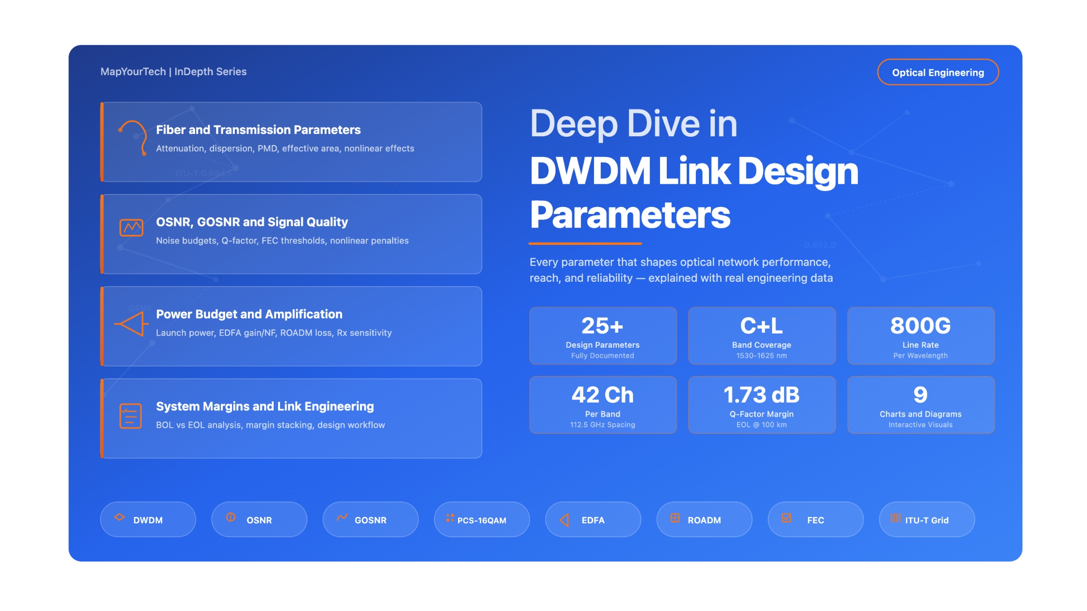

Deep Dive in DWDM Link Design Parameters
A comprehensive, vendor-neutral reference guide to every critical parameter that optical engineers must understand, calculate, and optimize for reliable Dense Wavelength Division Multiplexing network deployments
1. Introduction
Dense Wavelength Division Multiplexing (DWDM) is the dominant technology for long-haul, metro, and increasingly data center interconnect (DCI) optical transport. A single fiber pair can carry dozens or even hundreds of wavelength channels, each operating at line rates from 100 Gb/s to 800 Gb/s and beyond. However, the successful deployment of a DWDM link depends on careful engineering of numerous interdependent parameters. Getting even one parameter wrong can result in signal degradation, increased bit errors, or complete link failure.
This article provides a comprehensive, vendor-neutral reference to every critical parameter that an optical network designer encounters during DWDM link engineering. For each parameter, we explain what it is, why it matters, how it is calculated or measured, what typical values look like in real deployments, and what happens to the network when the parameter falls outside its acceptable range. The goal is to equip optical professionals, from early-career engineers to senior architects, with the knowledge needed to design, validate, and troubleshoot DWDM links with confidence.
The scope covers all parameters visible in modern link engineering tools and power budget reports, including fiber characteristics, channel plan definitions, transceiver specifications, OSNR and GOSNR budgets, FEC and Q-factor metrics, dispersion and polarization effects, amplifier performance, ROADM insertion losses, and overall system margins. Real engineering values from 100 km C-band and L-band link designs operating at 800 Gb/s line rates with 42 channels on 112.5 GHz spacing serve as practical references throughout the article.
Figure 1: Complete ecosystem of DWDM link design parameters, showing how each parameter category relates to physical network elements along the optical path.
2. Fiber and Transmission Medium Parameters
The optical fiber is the foundation of every DWDM link. Its physical characteristics determine the fundamental limits of what the link can achieve in terms of distance, capacity, and signal quality. Understanding fiber parameters is essential because they are fixed once the cable is in the ground — unlike transceiver or amplifier settings, fiber characteristics cannot be changed after deployment.
2.1 Fiber Attenuation
Fiber attenuation is the most basic and arguably most important fiber parameter. It describes how much optical power is lost per unit length as light travels through the fiber, measured in decibels per kilometer (dB/km). Attenuation is caused by absorption and scattering of photons within the glass medium.
For standard single-mode fiber (G.652.D), typical attenuation values are approximately 0.20 dB/km in the C-band (1530-1565 nm) and 0.22 dB/km in the L-band (1565-1625 nm). These are catalog values; actual deployed fiber may show slightly higher attenuation due to aging, splices, connectors, and environmental factors. Link designers typically add a fiber margin (commonly 3 dB for a 100 km span) to account for these real-world degradations, including future cable repairs that introduce additional splice losses.
Span Loss (dB) = α × L + Splice Losses + Connector Losses + Margin
Where:
α = Fiber attenuation coefficient (dB/km)
L = Span length (km)
Splice loss = Typically 0.05-0.1 dB per fusion splice
Connector loss = Typically 0.3-0.5 dB per mated pair
Margin = Design margin for aging and repairs (typically 1-3 dB)
Example: 100 km span on G.652.D fiber, C-band
Span Loss = 0.20 × 100 + 10 × 0.08 + 0 + 3
Span Loss = 20 + 0.8 + 3 = 23.8 dB (with margin)
Span Loss = 20.8 dB (without margin, BOL)
For network owners, fiber attenuation directly determines the maximum distance between amplifier sites and the total amplifier gain required. Lower attenuation fibers (such as ultra-low-loss fibers at 0.16 dB/km) can extend span lengths or reduce the number of inline amplifiers, lowering capital and operational costs. From the project reference data, a 100 km C-band path shows approximately 22 dB total span loss including the 3 dB fiber margin, confirming these engineering calculations.
2.2 Fiber Type and Standard
The ITU-T defines several fiber types, each with different characteristics relevant to DWDM transmission. The most commonly deployed fiber for DWDM is G.652.D (standard single-mode fiber, often called SMF or SSMF), which has zero dispersion at 1310 nm and positive dispersion of approximately 17 ps/(nm·km) at 1550 nm. Other fiber types include G.654 (cutoff-shifted fiber, optimized for submarine and long-haul with larger effective area), G.655 (non-zero dispersion-shifted fiber, or NZDSF), and G.657 (bend-insensitive fiber for access networks).
The fiber type affects multiple downstream parameters. The chromatic dispersion coefficient, the effective area (Aeff), and the nonlinear coefficient all depend on the fiber type. A larger effective area (as in G.654.E fibers with Aeff of 110-150 μm² compared to 80 μm² for G.652.D) reduces nonlinear impairments, enabling higher launch powers and longer reach without regeneration.
| Parameter | G.652.D (SSMF) | G.654.E (Large Aeff) | G.655 (NZDSF) |
|---|---|---|---|
| Attenuation at 1550 nm (dB/km) | 0.18-0.20 | 0.15-0.17 | 0.20-0.22 |
| CD at 1550 nm (ps/nm/km) | ~17 | ~20 | 2-8 |
| Aeff (μm²) | ~80 | 110-150 | 50-72 |
| PMD coefficient (ps/√km) | ≤0.1 | ≤0.1 | ≤0.1 |
| Nonlinear coefficient (1/W/km) | ~1.3 | ~0.7-0.9 | ~1.5-2.0 |
| Typical Application | Metro, Long-haul | Submarine, ULH | Legacy Long-haul |
Table 1: Comparison of key fiber types used in DWDM deployments.
2.3 Fiber Effective Area and Nonlinear Coefficient
The effective area (Aeff) of the fiber determines how concentrated the optical power is within the fiber core. A smaller effective area means higher power density, which increases nonlinear effects such as Self-Phase Modulation (SPM), Cross-Phase Modulation (XPM), Four-Wave Mixing (FWM), and Stimulated Raman Scattering (SRS). These nonlinear effects degrade signal quality and impose limits on the maximum power that can be launched into the fiber.
The nonlinear coefficient (γ) is inversely proportional to the effective area: γ = 2πn2 / (λ · Aeff), where n2 is the nonlinear refractive index of silica (approximately 2.6 × 10⁻²⁰ m²/W). For G.652.D fiber, γ is approximately 1.3 W-1km-1, while for large-area G.654.E fibers it drops to 0.7-0.9 W-1km-1.
The project reference data includes the parameter "Effective Accumulated Power" in the link engineering reports, which represents the cumulative nonlinear phase shift experienced by the signal. For the 100 km 800G link, this value is approximately 3.26 for C-band and 2.99 for L-band, reflecting the total nonlinear impairment accumulated along the fiber path.
Engineering Insight: When choosing fiber for new builds, operators deploying 400G and beyond should seriously consider G.654.E fiber for long-haul routes. The larger effective area provides 2-3 dB improvement in nonlinear tolerance, directly translating to longer reach or higher capacity without additional regeneration. The incremental fiber cost is recovered through reduced transponder and amplifier expenditure.
3. Channel Plan and Spectral Parameters
The channel plan defines how the available optical spectrum is divided among individual wavelength channels. These parameters determine the total capacity of the DWDM system and how efficiently the available bandwidth is used. A well-designed channel plan maximizes capacity while maintaining sufficient guard bands to prevent inter-channel interference.
3.1 Operating Band (C-Band and L-Band)
DWDM systems primarily operate in two transmission bands. The Conventional band (C-band) covers wavelengths from approximately 1530 nm to 1565 nm, corresponding to frequencies of approximately 191.3 THz to 196.1 THz. The Long-wavelength band (L-band) covers approximately 1565 nm to 1625 nm (184.5 THz to 191.3 THz). The C-band has lower fiber attenuation and is the preferred band for most deployments. The L-band provides additional capacity when the C-band is fully utilized.
Operating in both C+L bands effectively doubles the available spectrum but requires separate amplification chains (C-band and L-band EDFAs) and band splitters/combiners at each amplifier site. This adds equipment cost and complexity but is essential for networks requiring maximum fiber capacity. From the reference data, both a C-band path and an L-band path operate over the same 100 km fiber, each carrying 42 channels at 800 Gb/s, effectively doubling the fiber capacity to 67.2 Tb/s.
3.2 Channel Frequency and ITU-T Grid
Channel frequencies are defined according to the ITU-T G.694.1 standard, which specifies a frequency grid centered at 193.1 THz with spacing increments of 6.25 GHz. This "flex grid" approach allows operators to assign channel widths in multiples of 6.25 GHz (such as 12.5, 25, 37.5, 50, 75, 100, 112.5, 125, 137.5, 150, or 200 GHz), enabling flexible allocation of spectrum to match different transponder requirements.
In the reference data, the C-band channels span from 191.38125 THz to 195.99375 THz, while L-band channels occupy the lower frequency range. Each channel occupies 112.5 GHz of bandwidth, which is the slot width assigned on the flex grid. The channel center frequencies are spaced exactly 112.5 GHz apart, ensuring contiguous spectrum allocation without wasted gaps.
3.3 Channel Spacing and Bandwidth
Channel spacing (or channel bandwidth) is the spectral width allocated to each wavelength channel. This parameter has a direct relationship with spectral efficiency and system capacity. Narrower spacing allows more channels in the same spectrum but requires tighter filtering and higher-quality transponders. Common bandwidth values in modern deployments include 50 GHz (legacy), 75 GHz, 100 GHz, 112.5 GHz, 125 GHz, 137.5 GHz, and 150 GHz.
The choice of channel bandwidth depends on the modulation format and symbol rate of the transponder. A 98 Gbaud transponder with a roll-off factor of approximately 0.15 produces a signal with approximately 112 GHz of occupied bandwidth, making 112.5 GHz channel spacing a natural fit. Similarly, a 131.4 Gbaud transponder fits well within a 150 GHz slot. The channel bandwidth must be wide enough to pass the entire signal spectrum without clipping, but narrow enough to minimize wasted spectrum between channels.
3.4 Number of Channels
The total number of channels determines the aggregate capacity of the DWDM system. This parameter depends on the available spectrum width divided by the channel spacing. For the C-band with approximately 4.8 THz of usable spectrum and 112.5 GHz spacing, approximately 42 channels can be accommodated. With 150 GHz spacing, the count drops to approximately 32 channels. Using tighter 75 GHz spacing, up to 64 channels can be packed into the C-band, though each channel may carry a lower line rate due to the need for more aggressive spectral shaping.
| Channel BW (GHz) | C-Band Channels | L-Band Channels | C+L Total | Capacity at 400G | Capacity at 800G |
|---|---|---|---|---|---|
| 75 | ~64 | ~64 | ~128 | 51.2 Tb/s | 102.4 Tb/s |
| 100 | ~48 | ~48 | ~96 | 38.4 Tb/s | 76.8 Tb/s |
| 112.5 | ~42 | ~42 | ~84 | 33.6 Tb/s | 67.2 Tb/s |
| 150 | ~32 | ~32 | ~64 | 25.6 Tb/s | 51.2 Tb/s |
Table 2: Impact of channel bandwidth on system capacity for different line rates and band configurations.
Key Takeaways: Channel Plan Parameters
Read the Full Analysis with Premium
The remaining 80% of this article — the design numbers, trade-offs and field guidance — is part of MapYourTech Premium, along with the full premium library, courses and professional tools.

Optical Communications & Network Automation Expert | Author of 3 Books for Optical Engineers | Founder, MapYourTech
Optical networking engineer with nearly two decades of experience across DWDM, OTN, coherent optics, submarine systems, and cloud infrastructure. Founder of MapYourTech. Read full bio →
Follow on LinkedInRelated Articles on MapYourTech
You May Also Like
-
Free
-
July 11, 2026
-
Free
-
July 11, 2026
-
Free
-
July 11, 2026

