
Glass Core vs Air Core Fiber
A Comprehensive Technical Comparison of Traditional Solid-Core and Revolutionary Hollow-Core Optical Fiber Technologies
Introduction
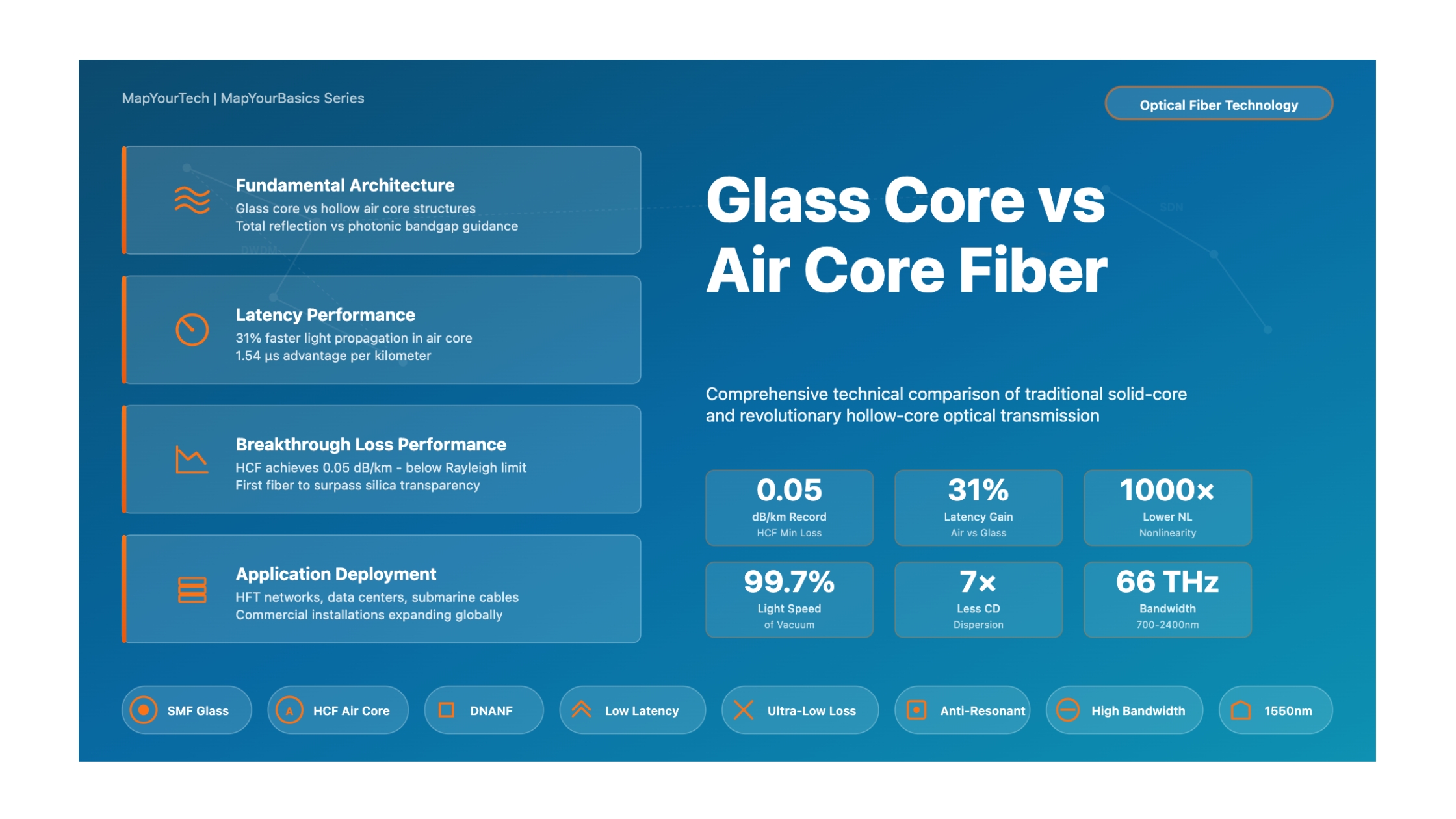
For over five decades, optical communications have relied on solid glass core fibers, where light travels through high-purity silica glass. This technology revolutionized global communications and established the foundation for the internet age. However, a fundamental paradigm shift is underway with the emergence of hollow-core fiber (HCF), also known as air-core fiber, where light propagates primarily through air rather than glass. This comparison examines the fundamental differences, performance characteristics, and practical implications of these two competing technologies.
Glass Core Fiber (SMF)
Traditional single-mode fiber uses total internal reflection to guide light through a solid silica glass core surrounded by a lower-refractive-index cladding. Light travels at approximately 200,000 km/s, about 31% slower than in vacuum due to the refractive index of 1.45.
Air Core Fiber (HCF)
Hollow-core fiber replaces the solid glass core with a hollow air-filled channel, using advanced microstructures (photonic bandgap or anti-resonant designs) to confine light. Light travels at 99.7% of vacuum speed, approximately 300,000 km/s, enabling fundamentally lower latency.
Fundamental Architecture Comparison
Standard Glass Core Fiber
Light confined by total internal reflection. Core diameter: 8-10 μm. Light travels through solid silica glass.
Hollow Core Fiber
Light confined by photonic bandgap or anti-resonant effects. Core diameter: 20-40 μm. Light travels through air.
Performance Metrics Comparison
Detailed Technical Comparison
| Parameter | Glass Core Fiber (SMF) | Air Core Fiber (HCF) |
|---|---|---|
| Propagation Medium | Solid silica glass core with refractive index ~1.45. Light travels through glass at ~200,000 km/s | Air or gas in hollow core (n≈1.0). Light travels at ~300,000 km/s, confined by microstructured glass cladding |
| Guidance Mechanism | Total internal reflection at core-cladding boundary. Requires core index higher than cladding | Photonic bandgap or anti-resonant effects using structured cladding (nested tubes, capillaries). Does not rely on index contrast |
| Core Diameter | 8-10 μm for standard SMF at 1550 nm. Relatively small core | 20-40 μm typical for low-loss HCF. Larger core required for confinement |
| Attenuation (Loss) |
Current best: 0.14-0.20 dB/km at 1550 nm Field deployed: 0.2-0.3 dB/km Limited by Rayleigh scattering (fundamental limit ~0.14 dB/km) Mature |
Record: 0.05 dB/km at 1550 nm (YOFC, 2025) DNANF: 0.08-0.11 dB/km demonstrated First fiber to break Rayleigh limit Loss dominated by surface scattering and leakage Breakthrough |
| Latency |
4.9-5.0 μs/km propagation delay Group velocity: ~200,000 km/s Refractive index causes 31-32% speed reduction vs vacuum |
3.35-3.46 μs/km propagation delay Group velocity: ~300,000 km/s (99.7% of c) 1.54 μs advantage per km 31% Faster |
| Chromatic Dispersion |
~17 ps/nm·km at 1550 nm for standard SMF Material + waveguide dispersion Requires compensation for long-haul links Zero-dispersion wavelength at 1310 nm |
2-3 ps/nm·km (70-85% lower) Dominated by waveguide dispersion Minimal material dispersion (air) Can be engineered to any wavelength 7× Lower |
| Nonlinear Effects |
Significant at high optical powers Self-phase modulation (SPM) Cross-phase modulation (XPM) Four-wave mixing (FWM) Stimulated Raman/Brillouin scattering Limits power per channel and total capacity |
Negligible nonlinearity (>1000× reduction) Minimal light-glass interaction Higher power handling without distortion Enables denser wavelength multiplexing Simpler DSP requirements 1000× Lower |
| Power Handling |
Limited by glass damage threshold Peak power: few megawatts Catastrophic self-focusing at high peak power Average power limited by thermal effects |
Much higher damage threshold (air) Can handle millijoule-level pulses Suitable for high-power laser delivery Minimal thermal issues 10×+ Higher |
| Bandwidth |
Limited to specific transmission windows C-band (1530-1565 nm) primary L-band (1565-1625 nm) extension Material absorption limits UV and mid-IR |
Octave-spanning bandwidth demonstrated 66 THz bandwidth with <0.2 dB/km loss (700-2400 nm) Can operate where glass is opaque UV to mid-IR transmission possible Ultra-Wideband |
| Security |
Can be tapped via bending or evanescent coupling Physical intrusion may not be immediately detectable Requires additional monitoring for tap detection |
Intrinsically more secure Physical intrusion causes significant signal loss Detectable via backscatter or mode changes Ideal for high-security applications Enhanced |
| Manufacturing Maturity |
Highly mature (50+ years) Standardized processes Multiple global suppliers Cost: $1-3 per meter (commodity) Mature |
Emerging technology Stack-and-draw fabrication Limited suppliers (Microsoft, YOFC, Linfiber) Higher cost (improving with scale) 47.5 km continuous draws demonstrated |
| Splicing & Connectivity |
Simple fusion splicing Low loss (<0.1 dB typical) Standardized connectors Field-deployable Standardized |
Challenging due to structure mismatch Specialized techniques required Loss: 0.5-2 dB typical Developing standards Mode field adapters needed |
| Bend Sensitivity |
Bend-optimized designs available Can tolerate tight bends (15-30 mm radius) Minimal loss increase with bending Robust |
Higher bend sensitivity Requires larger bend radii Trade-off between straight loss and bend loss Improving with design optimization |
| Mode Management |
Single-mode operation well-established Small core naturally supports single mode Higher-order modes (HOMs) suppressed Single-Mode |
Large core supports multiple modes Requires HOM suppression mechanisms Record HOMER: 5×10⁴ achieved Differential mode loss techniques applied |
| Temperature Sensitivity |
Glass properties vary with temperature Thermal expansion affects performance Well-characterized behavior |
Air properties nearly temperature-independent Lower thermal sensitivity Microstructure may have thermal considerations |
| Deployment Status |
Global infrastructure (>1 billion km installed) All major network types Submarine, long-haul, metro, access Industry standard Ubiquitous |
Early commercial deployments Niche applications: HFT, data centers Microsoft Azure network trials China Mobile commercial installation (July 2025) BT network trials |
Loss Evolution Timeline
Breaking the Rayleigh Limit
For 40 years, standard single-mode fiber loss plateaued at ~0.14 dB/km due to the fundamental Rayleigh scattering limit of silica glass. Hollow-core fiber has now achieved 0.05 dB/km, demonstrating that guidance in air can surpass the intrinsic transparency of the best glass. This represents a historic inversion where HCF is now the benchmark for optical transparency.
Attenuation Loss Progression
HCF loss has improved by 5.6× in just 5 years, while SMF has been stagnant for decades
Application Suitability
| Application | Glass Core Fiber | Air Core Fiber |
|---|---|---|
| High-Frequency Trading | Acceptable but higher latency adds microseconds that matter in arbitrage |
Ideal - 1.54 μs/km advantage critical Preferred |
| Data Center Interconnect | Current standard for short-reach and long-reach DCI |
Emerging for latency-critical AI/ML workloads Microsoft Azure deployment Growing |
| Submarine Cables |
Dominant technology Proven reliability Standard |
Potential for ultra-long unrepeated spans Lower loss enables longer distances Not yet deployed |
| Long-Haul Terrestrial |
Well-established with amplifier spacing every 80-100 km Established |
Could extend amplifier spacing significantly Lower nonlinearity enables higher power |
| High-Power Laser Delivery | Limited by damage threshold and nonlinearity |
Superior - millijoule pulses demonstrated Industrial, medical, scientific applications Superior |
| Gas Sensing | Not applicable - solid core |
Excellent - hollow core allows gas interaction Chemical detection, environmental monitoring Unique |
| Mid-IR Transmission | Limited by silica absorption beyond 2 μm |
Can operate where glass is opaque Medical, spectroscopy applications Enabled |
| Access Networks (FTTH) |
Ideal - low cost, robust, standardized Optimal |
Not cost-effective for residential access |
| 5G/6G Fronthaul | Current standard for mobile backhaul/fronthaul |
Potential for latency-critical applications Edge computing synchronization |
Key Challenges
Glass Core Challenges
- Fundamental Rayleigh scattering limit reached
- No further significant loss reduction possible
- Inherent latency penalty (31% slower than air)
- Nonlinear effects at high power
- Material dispersion requires compensation
- Limited bandwidth windows
Air Core Challenges
- Complex manufacturing (improving rapidly)
- Splicing and connectivity difficulties
- Higher bend sensitivity
- Higher-order mode management
- Limited supplier ecosystem
- Higher current cost (decreasing with scale)
- Lack of standardization
Performance Comparison by Metric
Relative Performance Comparison
Normalized comparison showing which technology excels in each category (longer bar = better performance)
Technology Roadmap and Future Outlook
Glass Core Fiber Future
Standard single-mode fiber technology is mature and approaching its fundamental limits. Future development focuses on:
- Multiband amplification (O, E, S, C, L bands) to maximize spectral efficiency
- Advanced modulation formats and spatial division multiplexing
- Improved manufacturing consistency and cost reduction
- Incremental improvements in bend performance and density
- Integration with photonic integrated circuits
No breakthrough reduction in attenuation or latency is expected - the technology has reached its physical limits.
Air Core Fiber Future
Hollow-core fiber is rapidly evolving with significant performance improvements expected:
- Loss targets: 0.03-0.05 dB/km across wider bandwidth by 2026-2027
- Manufacturing scale-up: Continuous draws exceeding 100 km
- Standardization: ITU-T and IEC standards development underway
- Splicing improvements: Target <0.3 dB field-deployable splices
- Cost reduction: Economy of scale as production volumes increase
- New designs: Simplified structures for easier manufacturing
- Material innovations: Non-silica glasses for extended wavelength range
HCF represents the next generation of optical fiber with performance headroom for continued improvement.
Economic Considerations
Glass Core Economics
Fiber Cost: $1-3 per meter (commodity pricing)
Installation: Standardized, low-cost splicing and termination
Maintenance: Well-understood, minimal specialized equipment
Amplifier Spacing: 80-100 km (established EDFA technology)
Total Cost: Highly optimized over decades
ROI: Predictable, proven business case
Air Core Economics
Fiber Cost: Currently higher (improving with scale)
Installation: Requires specialized splicing techniques and training
Maintenance: Developing expertise and tooling
Amplifier Spacing: Potentially 150+ km (fewer amplifiers needed)
Total Cost: Higher upfront, lower OPEX potential
ROI: Application-dependent - compelling for latency-critical and ultra-long-haul
Economic Crossover Points
HCF becomes economically attractive when:
- Latency reduction delivers measurable business value (HFT, real-time applications)
- Ultra-long unrepeated spans reduce CAPEX (submarine, remote terrestrial)
- Higher power handling enables simplified system design
- Reduced nonlinearity allows higher spectral efficiency
- Manufacturing costs approach parity with SMF through volume production
Summary and Conclusions
Glass core and air core fibers represent two fundamentally different approaches to optical transmission, each with distinct advantages and limitations.
Glass Core Fiber Strengths
- Mature, proven technology with global deployment
- Low cost and standardized infrastructure
- Simple splicing and connectivity
- Robust performance in diverse environments
- Well-established supply chain and expertise
Air Core Fiber Advantages
- Record-breaking low loss (0.05 dB/km) - surpasses silica limit
- 31% latency reduction - fundamental speed advantage
- 1000× lower nonlinearity - enables higher power and capacity
- 7× lower chromatic dispersion - simpler system design
- Ultra-wide bandwidth - octave-spanning transmission
- Enhanced security and unique sensing capabilities
The Path Forward
Rather than a complete replacement, hollow-core fiber will initially complement glass core fiber in applications where its unique advantages justify the additional complexity and cost. High-frequency trading networks, latency-critical data center interconnects, ultra-long-haul transmission, and high-power laser delivery are the early adopters. As manufacturing scales, costs decrease, and standards emerge, HCF deployment will expand into broader telecommunications infrastructure.
The breakthrough achievement of sub-0.1 dB/km loss in HCF represents a historic milestone - the first time any optical waveguide has exceeded the fundamental transparency of silica glass. This validates hollow-core fiber as the future direction for optical transmission, even as glass core fiber remains the foundation of current global communications infrastructure.
The transition is underway: Glass core fiber has reached its physical limits after 50 years of optimization. Hollow-core fiber, just beginning commercial deployment, already demonstrates superior performance in critical parameters and retains significant headroom for further improvement. The next decade will see both technologies coexisting, with HCF gradually capturing applications where latency, loss, nonlinearity, or bandwidth are the primary constraints.
Developed by MapYourTech Team
For educational purposes in Optical Networking Communications Technologies
Note: This comparison is based on industry standards, published research, and real-world deployment data current as of early 2025. Specific implementations may vary based on equipment vendors, network topology, and application requirements. Always consult with qualified network engineers and follow vendor documentation for actual deployments.
Feedback Welcome: If you have any suggestions, corrections, or improvements to propose, please feel free to write to us at [email protected]
Related Articles on MapYourTech


