
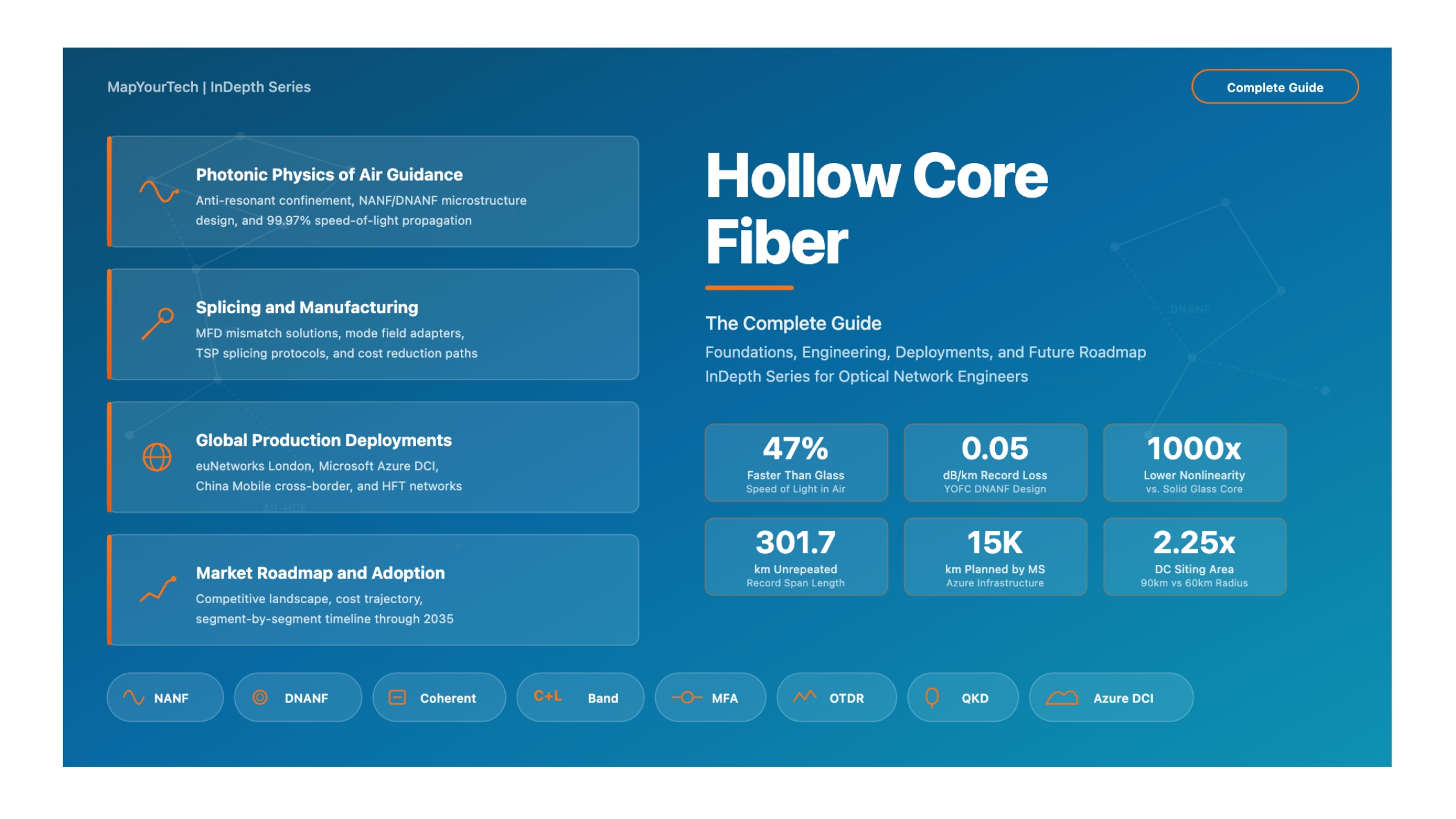
Hollow Core Fiber: The Physics of Light in Air
For over five decades, solid glass fiber has carried the world's data. Now, a revolutionary technology is replacing glass with air, enabling data to travel 47% faster and approaching the ultimate speed limit of light. This is the definitive engineering guide to understanding why Hollow Core Fiber matters, how it works, and what it promises for the future of networking.
1.1 Introduction
Optical fiber has been the backbone of global communications since the first commercial deployments in the 1970s. The fundamental design -- a solid glass core surrounded by glass cladding, using Total Internal Reflection (TIR) to guide light -- has proven remarkably successful. Billions of kilometers of standard Single-Mode Fiber (SMF) are installed worldwide, and the technology has evolved to support data rates exceeding 800 Gbps per wavelength across thousands of kilometers. Yet, the very material that made this revolution possible -- silica glass -- is now approaching fundamental physical limits that constrain future performance.
Hollow Core Fiber (HCF) represents the most significant architectural departure in optical fiber design since the invention of silica fiber itself. Instead of guiding light through a solid glass core, HCF transmits light through an air-filled channel surrounded by an engineered microstructured cladding. This seemingly simple substitution -- replacing glass with air -- produces profound performance changes. Data travels approximately 47% faster, nonlinear effects that distort signals at high power are virtually eliminated, chromatic dispersion drops by more than 80%, and the fiber becomes inherently more secure against physical tapping.
The technology has moved well beyond the laboratory. As of 2026, HCF carries live production traffic on financial trading networks in London, connects AI data centers for Microsoft's Azure cloud, and has been trialed by major operators including Comcast, BT, and China Mobile. The Prysmian Group has partnered with Relativity Networks to begin volume manufacturing, and YOFC has achieved a record-low attenuation of 0.05 dB/km -- now lower than the best conventional fiber.
This indepth article curated from all available public available data that provides a comprehensive engineering analysis of HCF technology. This establishes the physical foundations: why conventional fiber has reached its limits, how HCF overcomes them, and the fundamental performance advantages that make it a strategic asset for next-generation networks.
1.2 The Limits of Solid Glass: Why Conventional Fiber Cannot Go Further
To understand the value of HCF, it is essential to first understand why conventional SMF, despite its enormous success, is approaching performance boundaries dictated by the physics of silica glass. These are not engineering limitations that can be solved with better manufacturing -- they are fundamental material constraints.
1.2.1 The Rayleigh Scattering Floor
The dominant loss mechanism in modern SMF is Rayleigh scattering, caused by microscopic density fluctuations "frozen" into the glass structure during the fiber drawing process. This scattering scales inversely with the fourth power of wavelength (λ-4), which is why the telecommunications industry operates near 1550 nm -- it represents the optimal trade-off between Rayleigh scattering and infrared absorption in silica. The current record for SMF attenuation, achieved by Sumitomo Electric in 2018, stands at 0.142 dB/km at 1550 nm. This value is remarkably close to the theoretical Rayleigh scattering limit for silica glass, meaning there is virtually no room for further improvement.
1.2.2 The Nonlinear Shannon Limit
The capacity of any communication channel is bounded by the Shannon limit, which describes the maximum data rate achievable for a given signal-to-noise ratio (SNR). In optical fiber, this relationship is complicated by fiber nonlinearities -- effects where the refractive index of the glass changes slightly in response to the intensity of the light passing through it. The most significant of these is the Kerr effect, which gives rise to Self-Phase Modulation (SPM), Cross-Phase Modulation (XPM), and Four-Wave Mixing (FWM). These effects become increasingly problematic as data rates and channel counts increase, because higher modulation formats like 64QAM and 256QAM require tighter constellation spacing that is more sensitive to phase distortion. The result is the "nonlinear Shannon limit" -- a capacity ceiling for silica fiber estimated at approximately 100 Tbps in the C+L band for a single fiber. The industry is approaching this ceiling, and no amount of DSP improvement can overcome a fundamental material constraint.
1.2.3 Latency: The Speed of Light in Glass
Light in a vacuum travels at 299,792 km/s (c). In silica glass fiber, the group refractive index (ng ≈ 1.467) slows the signal to approximately 204,000 km/s -- roughly 68% of the speed of light in vacuum. This means that for every kilometer of fiber, the signal experiences about 4.9 microseconds of one-way delay. While this latency was historically acceptable, the emergence of applications such as high-frequency trading, distributed AI training, and real-time synchronous data replication between data centers has made every microsecond a strategic commodity. This latency penalty is intrinsic to the material and cannot be reduced through engineering improvements to solid glass fiber.
The Core Problem The three fundamental constraints of silica fiber -- Rayleigh scattering loss, nonlinear signal distortion, and propagation delay -- are all direct consequences of light traveling through solid glass. HCF addresses all three by removing the glass from the optical path entirely.
1.3 The Fundamental Concept: Guiding Light Through Air
Hollow Core Fiber solves the limitations of solid glass by guiding light through air instead of silica. The concept is elegant in its logic: if the problems come from the glass, remove the glass. Air has a refractive index very close to 1.0 (compared to 1.467 for silica), which means the Kerr nonlinear coefficient drops by a factor of approximately 1,000, Rayleigh scattering is eliminated because there is no solid medium to scatter, and the propagation speed increases by approximately 47% to nearly the speed of light in vacuum.
The engineering challenge, however, is significant. Total Internal Reflection -- the mechanism that has guided light in solid fibers since the 1960s -- requires that the core have a higher refractive index than the cladding. With an air core (n ≈ 1.0) surrounded by glass cladding (n ≈ 1.45), TIR cannot work. Light launched into such a structure would simply leak out. HCF requires entirely different physical mechanisms to confine light, which is why the technology took decades to develop from concept to practical fiber.
Two primary guidance mechanisms have been developed to solve this problem: the Photonic Bandgap (PBG) effect and Anti-Resonant (AR) reflection. Understanding these mechanisms is essential for any engineer evaluating HCF for deployment.
Figure 1: Structural and performance comparison between standard SMF and Hollow Core Fiber (NANF design). The NANF cross-section shows nested anti-resonant capillary tubes surrounding the central air core.
1.4 Guidance Mechanism 1: Photonic Bandgap Fibers (PBG-HCF)
The Photonic Bandgap Fiber was the first type of HCF to achieve practical performance. The concept is rooted in the physics of photonic crystals, first proposed in 1987. In a PBG-HCF, the cladding consists of a highly periodic lattice of air holes embedded in silica glass -- typically a hexagonal honeycomb structure. This regular arrangement creates a "photonic bandgap": a specific range of optical frequencies for which propagation through the cladding is forbidden by the periodic structure, much as electronic bandgaps in semiconductors prevent electrons from occupying certain energy states.
Read the Full Analysis with Premium
The remaining 88% of this article — the design numbers, trade-offs and field guidance — is part of MapYourTech Premium, along with the full premium library, courses and professional tools.
You May Also Like

-
Free
-
September 4, 2026

-
Premium
-
September 4, 2026

-
Premium
-
September 4, 2026