DWDM Technology
25 Essential Questions and Answers | MapYourTech
DWDM stands for Dense Wavelength Division Multiplexing, a technology used in optical networks to increase the capacity of data transmission by combining multiple optical signals with different wavelengths onto a single fiber.
DWDM works by assigning each incoming data channel a unique wavelength (or color) of light, combining these channels into a single optical fiber. This allows multiple data streams to travel simultaneously without interference.
DWDM stands for Dense Wavelength Division Multiplexing, while CWDM stands for Coarse Wavelength Division Multiplexing. The primary difference is in the channel spacing, with DWDM having much closer channel spacing, allowing for more channels on a single fiber.
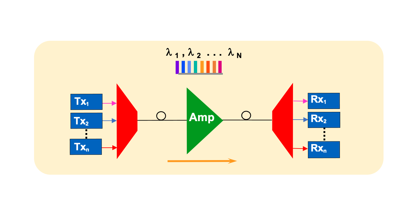
Key components of a DWDM system include optical transmitters, multiplexers, optical amplifiers, de-multiplexers, and optical receivers.
An OADM is a device that adds or drops specific wavelengths in a DWDM system while allowing other wavelengths to continue along the fiber.
DWDM increases network capacity by combining multiple optical signals with different wavelengths onto a single fiber, allowing for simultaneous data transmission without interference.
The typical channel spacing in DWDM systems is 100 GHz or 0.8 nm, although more advanced systems can achieve 50 GHz or even 25 GHz spacing.
Optical amplifiers are used to boost the signal strength in DWDM systems, compensating for signal loss and enabling long-distance transmission.
Maximum transmission distance for DWDM systems varies depending on factors such as channel count, fiber type, and amplification. However, some systems can achieve distances of up to 2,500 km or more.
Benefits of DWDM include increased network capacity, scalability, flexibility, and cost-effectiveness.
DWDM technology is commonly used in long-haul and metropolitan area networks (MANs), as well as in internet service provider (ISP) networks and data center interconnects.
A wavelength blocker is a device that selectively blocks or filters specific wavelengths in a DWDM system.
EDFAs are a type of optical amplifier that uses erbium-doped fiber as the gain medium, providing amplification for DWDM systems.
Chromatic dispersion is the spreading of an optical signal due to different wavelengths traveling at different speeds in the fiber. In DWDM systems, chromatic dispersion can cause signal degradation and reduce transmission distance.
A DCM is a device used to compensate for chromatic dispersion in DWDM systems, improving signal quality and transmission distance.
OSNR is a measure of the quality of an optical signal in relation to noise in a DWDM system. A higher OSNR indicates better signal quality.
PMD is a phenomenon where different polarization states of light travel at different speeds in the fiber, causing signal distortion and degradation in DWDM systems. PMD can limit the transmission distance and data rates.
A dispersion management strategy helps to minimize the impact of chromatic dispersion and PMD, ensuring better signal quality and longer transmission distances in DWDM systems.
A tunable optical filter is a device that can be adjusted to selectively transmit or block specific wavelengths in a DWDM system, allowing for dynamic channel allocation and reconfiguration.
A ROADM is a device that allows for the flexible addition, dropping, or rerouting of wavelength channels in a DWDM system, enabling dynamic network reconfiguration.
DWDM can be used to create diverse optical paths, providing redundancy and protection against network failures or service disruptions.
Nonlinear effects such as self-phase modulation, cross-phase modulation, and four-wave mixing can cause signal degradation and limit transmission performance in DWDM systems.
FEC is a technique used to detect and correct errors in DWDM systems, improving signal quality and transmission performance.
DWDM allows for the dynamic allocation and reconfiguration of wavelength channels, providing flexibility to adapt to changing network demands and optimize network resources.
The future of DWDM technology includes continued advancements in channel spacing, transmission distances, and data rates, as well as the integration of software-defined networking (SDN) and other emerging technologies to enable more intelligent and adaptive optical networks.
Long answers for previous 25 Questions
Dense Wavelength Division Multiplexing (DWDM) is an advanced optical fiber technology that enables multiple optical carrier signals to coexist on a single fiber by using different wavelengths (colors) of laser light. This technology has revolutionized telecommunications by dramatically increasing fiber capacity without requiring new fiber installation.
DWDM operates on the principle that multiple wavelengths of light can travel through fiber simultaneously without interfering with each other. Systems typically operate in the C-band (1530-1565 nm) of the optical spectrum, with modern systems also utilizing the L-band (1565-1625 nm) for expanded capacity. The technology uses precise ITU-T G.694.1 grid specifications to ensure compatibility across vendors and network segments.
Modern DWDM systems can support channel spacing as narrow as 0.8 nm (100 GHz) or 0.4 nm (50 GHz), allowing up to 160 wavelengths per fiber in advanced deployments. Each wavelength can carry data rates from 100 Gbps to 400 Gbps and beyond, with 800G and 1.6 Tbps per wavelength emerging in 2025. The capacity multiplication achieved—often 40× to 160× compared to single-wavelength systems—makes DWDM essential for meeting exponential traffic growth while maximizing return on fiber infrastructure investment.
DWDM operates through a systematic process of wavelength multiplexing and demultiplexing. At the transmitting end, individual data streams are modulated onto separate laser sources, each operating at a precisely controlled wavelength according to the ITU grid. These wavelengths are combined using optical multiplexers employing technologies such as Arrayed Waveguide Gratings or thin-film filters to merge signals with minimal insertion loss (typically 1-5 dB depending on channel count).
The combined optical signal travels through the fiber, with each wavelength maintaining its distinct identity. The fiber's low attenuation in the C-band (approximately 0.19-0.22 dB/km at 1550 nm) enables long-distance transmission, though signal degradation from fiber attenuation necessitates periodic amplification using Erbium-Doped Fiber Amplifiers (EDFAs) or Raman amplifiers at intervals of 50-100 km in long-haul systems.
At the receiving end, a demultiplexer separates the composite signal back into individual wavelength channels using the inverse operation of the multiplexer with equal precision. Each separated wavelength is directed to its dedicated receiver for optical-to-electrical conversion and data recovery. The demultiplexer must achieve high isolation between channels (typically greater than 30 dB) to prevent crosstalk and signal degradation, ensuring each wavelength is cleanly separated without interference from adjacent channels.
Dense Wavelength Division Multiplexing (DWDM) and Coarse Wavelength Division Multiplexing (CWDM) represent fundamentally different approaches to wavelength multiplexing. The primary distinction lies in channel spacing. DWDM uses tightly spaced channels at 0.8 nm (100 GHz) or 0.4 nm (50 GHz), enabling 40 to 160+ channels on a single fiber. CWDM employs much wider spacing of 20 nm, limiting systems to a maximum of 18 channels across the 1270-1610 nm range.
This spacing difference cascades into other distinctions. DWDM requires temperature-stabilized lasers with precise wavelength control (typically ±0.01 nm or better), achieved through thermoelectric cooling and wavelength locking. CWDM uses uncooled lasers with relaxed wavelength tolerance (±3 nm), reducing component costs but limiting total capacity. The tight channel spacing in DWDM demands sophisticated optical filters and precise thermal management, increasing system cost but enabling much higher capacity and longer transmission distances.
DWDM can leverage Erbium-Doped Fiber Amplifiers operating in the C-band and L-band to simultaneously amplify all channels, enabling ultra-long-haul transmission of 1000-2500 km or more. CWDM's wide wavelength range prevents the use of optical amplifiers, as no amplifier technology efficiently covers 1270-1610 nm, thus limiting CWDM to unamplified distances typically under 80 km. DWDM systems are ideal for long-haul networks, submarine cables, and high-capacity metro networks, while CWDM suits enterprise networks, data center interconnects, and access networks where lower cost matters more than maximum capacity.
A complete DWDM system comprises several sophisticated components. Optical transmitters (transponders) convert incoming client signals into optical signals at specific DWDM wavelengths, incorporating tunable lasers that can be set to any ITU grid wavelength for operational flexibility. Modern coherent transponders transmit at 400 Gbps or higher using sophisticated modulation formats like DP-16QAM or DP-64QAM, while also performing wavelength conversion, signal regeneration, protocol conversion, and forward error correction encoding.
Multiplexers combine multiple wavelength-specific signals into a single composite optical signal. Common technologies include Arrayed Waveguide Gratings offering excellent performance for high channel counts with insertion loss around 3-5 dB, and thin-film filters providing superior isolation (greater than 30 dB) commonly used in systems with 50 GHz or 100 GHz channel spacing. Optical amplifiers are critical for extending transmission reach, with Erbium-Doped Fiber Amplifiers (EDFAs) providing 20-30 dB gain across the C-band or L-band with noise figures of 4-6 dB, enabling simultaneous amplification of all DWDM channels.
Demultiplexers at the receiving end separate the composite signal back into individual wavelength channels, typically using the same underlying technology as multiplexers. Optical receivers convert optical signals to electrical form, with modern coherent receivers employing digital signal processing to compensate for transmission impairments including chromatic dispersion, polarization mode dispersion, and phase noise. Additional critical components include Optical Add-Drop Multiplexers enabling selective wavelength management at intermediate nodes, Optical Channel Monitors providing real-time monitoring of individual channel parameters, and gain flattening filters ensuring equal amplification across all channels in multi-span systems.
An Optical Add-Drop Multiplexer (OADM) is a network device that selectively adds or drops specific wavelengths from a multi-wavelength DWDM signal while allowing other wavelengths to pass through unaffected. This capability enables flexible wavelength routing in optical networks, creating more efficient architectures without requiring full optical-electrical-optical conversion at intermediate nodes. OADMs use wavelength-selective optical filtering to extract specific wavelengths for local access while maintaining pass-through traffic in the optical domain.
The evolution from fixed to reconfigurable OADMs (ROADMs) has been transformative. Early fixed OADMs used predetermined optical filters set during installation, lacking flexibility for network changes. Modern ROADMs employ wavelength selective switch (WSS) technology providing remote software-controlled wavelength selection. WSS devices offer minimum reconfigurable bandwidth steps of 6.25 GHz or 12.5 GHz aligned to the ITU grid, switching times under 20 milliseconds for protection switching, and wavelength-dependent optical attenuation profiles for dynamic gain equalization.
Advanced ROADMs incorporate colorless, directionless, and contentionless (CDC) capabilities. Colorless means any wavelength can be added or dropped at any port. Directionless allows signals to be routed to any network direction without physical recabling. Contentionless enables multiple instances of the same wavelength to coexist at the ROADM without conflict. In submarine cable systems, ROADM branching units enable flexible bandwidth allocation among multiple landing points, significantly reducing required fiber pairs compared to full fiber drop configurations while maintaining wavelength reuse capability and providing protection switching for network resilience.
DWDM achieves dramatic capacity increases through wavelength-based multiplication, enabling a single optical fiber to carry data at rates impossible with single-wavelength transmission. The fundamental principle allows multiple independent optical carriers at different wavelengths to coexist on the same fiber without mutual interference when properly engineered. Modern DWDM systems in the C-band with 50 GHz channel spacing can accommodate 88 channels, while 100 GHz spacing supports 44 channels, with each wavelength potentially carrying 100 Gbps to 400 Gbps or higher.
Capacity multiplication occurs through both increased channel count and higher per-wavelength rates. Early DWDM systems carried 2.5-10 Gbps per wavelength. Today's systems routinely transmit 100-400 Gbps per wavelength using advanced coherent modulation formats, with 800 Gbps and 1.6 Tbps per wavelength emerging in 2025. Spectral efficiency improvements through advanced modulation including QPSK, 16-QAM, and 64-QAM, combined with dual-polarization multiplexing, enable 2 to 12 bits per symbol, dramatically increasing capacity within the same optical bandwidth.
The economic impact is substantial. A typical C-band DWDM system with 80 channels at 200 Gbps each achieves 16 Tbps total capacity on a single fiber pair. Without DWDM, achieving this would require 160 dedicated fiber pairs at 100 Gbps each—often physically impossible given cable size constraints and economically prohibitive given fiber installation costs. DWDM provides this capacity multiplication without installing new fiber, offering scalability through adding wavelengths, upgrading per-wavelength rates, implementing more efficient modulation, or expanding to C+L band operation, all while maintaining protocol and rate transparency across different wavelength channels.
Channel spacing in DWDM systems, defined by ITU-T Recommendation G.694.1, represents the frequency or wavelength separation between adjacent optical channels. The most common spacing in deployed systems is 100 GHz (approximately 0.8 nm), providing an excellent balance between spectral efficiency and filter performance, allowing up to 88 channels in the C-band. Many modern systems employ 50 GHz (approximately 0.4 nm) spacing, doubling potential channel count to 176 in the C-band, though practical deployments typically use fewer channels due to guardband requirements and edge effects.
For ultra-dense applications, particularly submarine systems and advanced metro networks, 25 GHz spacing enables theoretically 352 channels in the C-band. However, this presents significant engineering challenges including stringent laser wavelength stability (±1.25 GHz or better), sharper optical filter responses to prevent adjacent channel interference, increased susceptibility to nonlinear effects like cross-phase modulation and four-wave mixing, and higher ROADM complexity. The relationship between wavelength and frequency spacing varies with center wavelength, with 100 GHz at 1550 nm corresponding to approximately 0.8 nm wavelength spacing.
Flexible grid technology, defined in ITU-T G.694.1 Amendment 2, enables variable frequency slot widths in 6.25 GHz or 12.5 GHz increments, allowing optimization of spectrum usage based on actual signal requirements. A 400G DP-16QAM signal requiring approximately 75 GHz can be allocated exactly that amount, while a 100G DP-QPSK signal requiring only 37.5 GHz receives proportionally less, maximizing spectral efficiency. Channel spacing selection impacts nonlinear impairments, with tighter spacing increasing cross-phase modulation and four-wave mixing severity, requiring careful power management and potentially limiting transmission distance despite electronic compensation capability.
Optical amplifiers enable long-distance DWDM transmission by compensating for signal attenuation directly in the optical domain without optical-electrical-optical conversion. They represent a transformative technology that made practical DWDM possible by simultaneously amplifying all wavelength channels within their gain bandwidth, eliminating the need for per-channel regeneration that would require hundreds of transponders at each amplification site. EDFAs are the predominant amplifier technology, using erbium-doped fiber as the gain medium pumped with laser light at 980 nm or 1480 nm wavelengths.
When pump photons enter the erbium-doped fiber, they excite erbium ions from ground state to higher energy levels. These excited ions release stored energy through stimulated emission when signal photons at 1550 nm wavelengths interact with them, generating additional photons coherent with the incoming signal photons, thus amplifying the signal. EDFAs provide gain across the C-band (1530-1565 nm) and L-band (1565-1625 nm), with typical gain values of 20-30 dB and noise figures of 4-6 dB for 980 nm pumping, approaching the theoretical quantum limit of 3 dB.
In long-haul DWDM systems, amplifiers are deployed as booster amplifiers after transmitters to maximize launched power (+17 to +23 dBm per channel), inline amplifiers every 80-100 km to compensate for span loss (20-25 dB), and pre-amplifiers before receivers to boost weak signals above sensitivity thresholds. While amplifying signals, EDFAs introduce amplified spontaneous emission (ASE) noise that accumulates with each stage, progressively degrading optical signal-to-noise ratio. In a 20-span system spanning 2000 km, OSNR typically degrades from 35 dB initially to 15-17 dB after accumulation, remaining sufficient for coherent detection with modern FEC but demonstrating why optical amplification with careful noise management is essential for economically viable long-distance DWDM.
Maximum transmission distance for DWDM systems varies significantly based on modulation format, channel data rate, fiber type, amplification strategy, and acceptable bit error rate at the receiver. Modern coherent DWDM systems routinely achieve distances exceeding 2,500 km in terrestrial networks, with specialized submarine systems spanning over 10,000 km across ocean basins. The distance is fundamentally limited by optical signal-to-noise ratio degradation as each optical amplifier adds amplified spontaneous emission noise while boosting signal power.
Distance-limiting factors include fiber attenuation at approximately 0.19-0.22 dB/km requiring periodic amplification, OSNR degradation accumulating through cascaded amplifiers, chromatic dispersion causing pulse broadening (though compensatable through DSP in coherent systems), polarization mode dispersion becoming limiting at higher symbol rates, and fiber nonlinearities including self-phase modulation, cross-phase modulation, and four-wave mixing that intensify with increased power and distance. In a 20-amplifier-span system, OSNR typically degrades by 13 dB from single-span values, limiting achievable modulation format complexity.
Modulation format dramatically affects distance. DP-QPSK with lowest OSNR requirement (~10-12 dB) achieves maximum distances of 3,000-4,000 km in terrestrial systems and 10,000+ km in optimized submarine systems with Raman amplification. DP-16QAM requiring better OSNR (~16-18 dB for 200G, ~20-22 dB for 400G) typically reaches 1,000-2,000 km. DP-64QAM with very demanding OSNR requirements (~25-28 dB) is limited to metro and regional distances of 200-600 km. Forward error correction extends distance by providing 10-11 dB effective OSNR gain through soft-decision codes, enabling operation at lower raw OSNR values while introducing 20-25% overhead that reduces net spectral efficiency.
DWDM delivers transformative benefits across technical, operational, and economic dimensions. The most obvious benefit is massive capacity multiplication by factors of 40× to 160× or more compared to single-wavelength systems. A single fiber pair can carry 10+ Tbps using current technology, with laboratory demonstrations exceeding 100 Tbps. This capacity multiplication is achieved without installing new fiber—critical since fiber installation represents the dominant cost in network deployment, particularly in metropolitan areas and submarine environments where costs reach hundreds of millions to billions of dollars.
Economic advantages stem from dramatic cost-per-bit reductions as channel count increases. While a 96-channel DWDM system costs more in absolute terms than a 40-channel system, the cost per Gbps of capacity is typically 40-60% lower. Network operators report total cost of ownership reductions of 70-80% compared to deploying equivalent capacity through multiple single-wavelength systems or new fiber installation. DWDM enables efficient utilization of existing fiber infrastructure, particularly dark fiber deployed in earlier buildouts, immediately multiplying capacity by 40× to 80× without civil works or cable installation.
Protocol and rate transparency allows different services to coexist on the same fiber—10 Gigabit Ethernet, 100 Gigabit Ethernet, OTN frames, and Fibre Channel storage traffic can simultaneously use different wavelengths. This transparency enables gradual network evolution with 400G channels introduced alongside existing 100G channels without service disruption. Scalability along multiple dimensions—adding wavelengths, upgrading individual wavelengths to higher rates, increasing spectral efficiency through advanced modulation, or expanding to C+L band operation—provides clear upgrade paths protecting infrastructure investment. The combination of long-distance transmission capability, wavelength-level operational flexibility, sophisticated protection schemes, and integration with software-defined networking makes DWDM the essential capacity foundation for modern telecommunications infrastructure.
DWDM technology pervades modern telecommunications across diverse applications. Long-haul terrestrial networks spanning 500-2,500 km interconnect major metropolitan areas using DWDM with 80-96 channels at 100-400 Gbps per wavelength, providing fiber pair capacities of 8-38 Tbps. These systems eliminate expensive electrical regeneration sites through optical amplification, making them economically compelling for carriers. Submarine cable systems spanning 5,000-13,000 km across oceans represent perhaps the most dramatic DWDM application, deploying 6-24 fiber pairs with 80-160 wavelengths per fiber carrying the majority of intercontinental internet traffic.
Metropolitan area networks (MANs) operate over 20-200 km using DWDM with 40-96 channels, often employing higher-order modulation like DP-16QAM or DP-64QAM impractical in long-haul systems. ROADMs provide crucial flexibility for dynamic wavelength routing in mesh topologies interconnecting data centers, cellular base stations, and internet exchange points. Data center interconnect applications have grown explosively with cloud computing, using DWDM across multiple distance ranges—campus DCI at 1-10 km with passive multiplexers, metro DCI at 10-80 km with amplified DWDM and ROADMs, and regional/long-haul DCI at 80-2,000 km with full coherent systems.
Mobile backhaul and fronthaul for 5G networks leverage DWDM to aggregate traffic from multiple cell sites, with each site potentially requiring 10-100 Gbps. Internet service providers use DWDM backbone networks to scale router interconnections from 100 Gbps to multi-terabit capacities without proportional router port count increases. Enterprise and government private networks deploy DWDM for secure, dedicated high-capacity connectivity, with financial institutions using it to interconnect trading floors and data centers with microsecond-level latency requirements. The versatility across these diverse applications stems from DWDM's fundamental capacity multiplication combined with protocol transparency, scalability, and decreasing cost per bit, positioning it as the essential foundation for global telecommunications infrastructure.
A wavelength blocker is a specialized optical component providing selective blocking or filtering of specific wavelengths in a DWDM system while allowing other wavelengths to pass unimpeded. This device enables wavelength-selective attenuation or complete blocking, facilitating flexible network management, fault isolation, and power management at wavelength granularity. Wavelength blockers function as wavelength-selective attenuators using optical filtering technologies such as thin-film interference filters, fiber Bragg gratings, or integrated optical devices to achieve wavelength discrimination with blocking ratios typically exceeding 30-40 dB for targeted wavelengths while introducing minimal insertion loss (less than 1 dB) for pass-through wavelengths.
In fault isolation scenarios, a malfunctioning transmitter generating excessive noise or operating at incorrect power levels can contaminate the DWDM signal and cause receiver overload or inter-channel interference. A wavelength blocker can immediately suppress the problematic channel while troubleshooting proceeds, preventing service impact on remaining channels. This rapid fault isolation capability significantly improves network availability by containing failures to single wavelengths rather than entire fiber systems. Power equalization applications use wavelength blockers to dynamically adjust per-channel power levels, compensating for variations in transponder output power, wavelength-dependent amplifier gain, or fiber plant loss changes.
Modern reconfigurable optical add-drop multiplexers (ROADMs) incorporate wavelength blocking functionality as an integrated feature through wavelength selective switches, which inherently provide wavelength-by-wavelength attenuation control, effectively combining routing and blocking in single devices. This integration allows remote control through network management software, enabling rapid fault response and streamlined network configuration changes. Performance specifications include blocking isolation (typically greater than 30-40 dB), insertion loss for pass-through wavelengths (typically less than 1 dB), wavelength selectivity enabling blocking one channel without affecting adjacent channels (requiring sharp filter responses especially at 50 GHz or 25 GHz spacing), polarization-dependent loss (typically less than 0.5 dB), and response time for tunable blockers (milliseconds for mechanical systems, microseconds for optical switches).
Erbium-Doped Fiber Amplifiers (EDFAs) represent transformative technology enabling practical long-distance DWDM transmission by amplifying optical signals directly in the optical domain without optical-electrical-optical conversion. EDFAs use optical fiber doped with erbium ions as the gain medium, providing simultaneous amplification of multiple wavelength channels across the telecommunications C-band and L-band with high gain, low noise, and excellent reliability. When pump light at 980 nm or 1480 nm is coupled into erbium-doped fiber, pump photons excite erbium ions from ground state to higher energy levels, which then release stored energy through stimulated emission when signal photons around 1550 nm interact with them, generating additional coherent photons that amplify the signal.
A practical EDFA comprises erbium-doped fiber (typically 10-50 meters with optimized erbium concentration), pump lasers providing optical energy (980 nm pumping generally provides better noise figure of 3-5 dB while 1480 nm offers higher conversion efficiency), WDM couplers combining pump light with signal light, optical isolators preventing backward-propagating light from creating instabilities, and gain flattening filters compensating for the naturally non-uniform gain spectrum of erbium to ensure equal amplification across all DWDM channels. EDFAs can employ co-propagating pumping (lower noise but higher pump power required), counter-propagating pumping (higher output power capability), or bidirectional pumping using both simultaneously (optimal combination of low noise and high output power).
While amplifying signals, EDFAs introduce amplified spontaneous emission (ASE) noise from spontaneous decay of excited erbium ions, with quality quantified by noise figure representing signal-to-noise ratio degradation. EDFAs with 980 nm pumping typically achieve 4-6 dB noise figures approaching the theoretical quantum limit of 3 dB. In multi-span DWDM systems, ASE noise accumulates with each amplifier stage, progressively degrading optical signal-to-noise ratio and ultimately limiting maximum transmission distance. The gain spectrum exhibits significant wavelength dependence requiring gain flattening filters to create flat effective gain (typically within ±0.5 dB across the band), preventing channels at gain peak from dominating while band-edge channels fade. EDFAs transformed optical networking from niche technology into the global telecommunications foundation, enabling exponential capacity growth over three decades, with ongoing refinements in pump configurations, gain control algorithms, and integration with Raman amplification continuing to push performance boundaries.
Chromatic dispersion is one of the most significant transmission impairments in DWDM systems, causing temporal pulse broadening that limits data rates and transmission distances when uncompensated. This phenomenon occurs because different wavelength components of an optical signal travel at slightly different velocities through fiber, causing signal pulses to spread in time as they propagate. Standard single-mode fiber exhibits chromatic dispersion of approximately 17 ps/(nm·km) at 1550 nm, meaning a signal with 1 nm spectral width accumulates 1,700 ps of dispersion over 100 km, potentially causing severe inter-symbol interference at high data rates.
The relationship between chromatic dispersion and signal degradation depends critically on modulation format and symbol rate. Simple on-off keying (OOK) systems are highly sensitive to dispersion, with 10 Gbps systems limited to roughly 50-80 km uncompensated transmission. Modern coherent systems with digital signal processing enable electronic dispersion compensation in the digital domain, correcting tens of thousands of picoseconds per nanometer of accumulated chromatic dispersion. However, the interaction between chromatic dispersion and fiber nonlinearities still impacts performance, requiring careful power management and modulation format selection even when electronic compensation capability exists.
In pre-coherent DWDM systems, chromatic dispersion was mitigated through dispersion compensating fiber (DCF) with negative dispersion characteristics or fiber Bragg gratings providing wavelength-specific compensation. These approaches introduced insertion loss and added system complexity. The transition to coherent detection with DSP-based electronic dispersion compensation has eliminated the need for physical dispersion compensation modules in most modern systems, reducing cost and complexity while improving flexibility. The trade-off is increased digital signal processing complexity and power consumption at receivers, though advancing electronics technology continues reducing DSP cost and power requirements, making electronic dispersion compensation the standard approach in contemporary DWDM systems operating at 100 Gbps and higher data rates.
A Dispersion Compensating Module (DCM) is a passive optical component containing specialized dispersion compensating fiber (DCF) exhibiting chromatic dispersion of opposite sign to standard transmission fiber, used historically to counteract accumulated chromatic dispersion in optical transmission systems. DCFs typically have dispersion values of -80 to -100 ps/(nm·km) compared to +17 ps/(nm·km) for standard single-mode fiber, allowing relatively short lengths of DCF to compensate for dispersion accumulated over much longer transmission fiber spans. A typical implementation might use 20 km of DCF to compensate for dispersion in a 100 km span of standard fiber.
DCMs were essential in pre-coherent DWDM systems, particularly for 10 Gbps and 40 Gbps transmission where accumulated chromatic dispersion would otherwise cause severe inter-symbol interference limiting transmission distance to under 100 km uncompensated. The modules introduced several challenges including insertion loss (typically 5-10 dB requiring additional amplification), cost and complexity (each DCM represents a discrete optical component requiring installation and maintenance), limited wavelength range (DCFs compensate optimally for specific wavelength bands, with imperfect compensation at band edges), and PMD introduction (DCF itself can introduce polarization mode dispersion degrading signal quality).
The advent of coherent detection with digital signal processing has fundamentally changed dispersion management strategies. Modern coherent receivers employ DSP algorithms that electronically compensate for chromatic dispersion in the digital domain, handling tens of thousands of picoseconds per nanometer with no physical DCMs required. This electronic compensation offers several advantages over physical DCMs including zero insertion loss beyond the receiver's inherent requirements, complete wavelength-range coverage with uniform compensation across all channels, reconfigurability allowing the same hardware to adapt to different fiber plants and distances, and elimination of physical components reducing cost and failure points. Consequently, new DWDM systems deploying coherent transmission at 100 Gbps and higher have largely eliminated DCMs, preferring uncompensated or lightly-compensated transmission links with full electronic dispersion compensation at receivers, representing a significant architectural shift in optical network design.
Optical Signal-to-Noise Ratio (OSNR) is the fundamental quality metric for optical communication systems, quantifying the ratio of signal power to optical noise power (primarily amplified spontaneous emission from optical amplifiers) within a defined optical bandwidth, conventionally 0.1 nm (approximately 12.5 GHz) at 1550 nm. OSNR directly determines the bit error rate achievable at the receiver, making it the critical parameter for designing and troubleshooting DWDM systems. OSNR is typically expressed in decibels as 10×log₁₀(P_signal/P_noise), with higher values indicating better signal quality and lower bit error rates.
OSNR requirements vary dramatically with modulation format complexity. Simple DP-QPSK modulation (100G) requires approximately 10-12 dB OSNR for error-free operation with standard forward error correction, making it suitable for long-haul transmission where OSNR degrades over distance. DP-16QAM (200G-400G) demands 16-20 dB OSNR depending on symbol rate and FEC strength, limiting achievable distance compared to QPSK. DP-64QAM (400G-600G) requires 25-28 dB or higher OSNR, restricting it to metro and regional applications where distances are shorter and OSNR degradation is limited. Advanced soft-decision FEC can effectively improve OSNR by 10-11 dB through sophisticated error correction, enabling operation at lower raw OSNR values at the cost of 20-25% overhead reducing net data rate.
In multi-span DWDM systems, OSNR degrades cumulatively as each optical amplifier adds ASE noise while boosting signal power. The degradation follows the relationship OSNR_total = OSNR_single - 10×log₁₀(N) where N is the number of amplifier spans. A system with single-span OSNR of 30 dB will degrade to approximately 17 dB after 20 spans, sufficient for DP-QPSK but marginal for DP-16QAM and inadequate for DP-64QAM. This fundamental OSNR accumulation mechanism determines maximum achievable transmission distance for given modulation formats, making OSNR optimization through low-noise amplifiers, appropriate span lengths, and careful power management critical for maximizing DWDM system performance and reach.
Polarization Mode Dispersion (PMD) arises from fiber birefringence causing the two orthogonal polarization modes of light to travel at slightly different speeds, resulting in differential group delay (DGD) that varies randomly with time, temperature, and mechanical stress on the fiber. PMD accumulates statistically as the square root of distance according to Δt_PMD = D_PMD × √L, where D_PMD is the PMD coefficient (typically 0.1-0.5 ps/√km for modern fibers) and L is fiber length. Unlike chromatic dispersion which is deterministic and stable, PMD varies randomly over time scales of hours to days as environmental conditions change fiber birefringence characteristics.
PMD becomes increasingly problematic at higher symbol rates where even small differential delays represent significant fractions of the symbol period. For a 32 GBaud system (symbol period of approximately 31 ps), a PMD value of 3-5 ps already represents 10-15% of the symbol period, approaching limits of practical compensation. The random time-varying nature of PMD requires adaptive compensation algorithms that continuously track PMD changes, adding complexity compared to static chromatic dispersion compensation. In long-haul systems spanning 1,000-2,000 km, accumulated PMD with D_PMD of 0.2 ps/√km would be approximately 6-9 ps, potentially limiting performance at 64 GBaud symbol rates.
Modern coherent receivers with polarization-diverse detection employ adaptive digital signal processing to track and compensate PMD dynamically in real-time through multiple-input multiple-output (MIMO) equalization algorithms. These algorithms use adaptive filters that adjust tap weights continuously to track PMD variations, effectively compensating differential group delays up to approximately 10-20% of the symbol period depending on implementation complexity. However, extreme PMD values exceeding DSP compensation capability can limit system performance, particularly at high symbol rates, making PMD a consideration in fiber plant selection for high-capacity long-haul systems. Legacy fiber plants deployed before PMD optimization may exhibit higher PMD coefficients (0.5-1.0 ps/√km), potentially requiring PMD compensation strategies or limiting achievable symbol rates in modern coherent system upgrades.
Dispersion management strategies optimize the interaction between chromatic dispersion and fiber nonlinearities to maximize system performance, particularly in high-capacity long-haul DWDM systems. Traditional dispersion management involved alternating spans of positive and negative dispersion fiber to maintain low local dispersion throughout the link, reducing nonlinear penalty while keeping total accumulated dispersion manageable for electronic or optical compensation. This approach created dispersion maps where each span's dispersion was largely compensated by the following span, preventing excessive local dispersion that would enhance nonlinear effects like four-wave mixing.
In pre-coherent systems using direct detection, dispersion management was critical since receivers could not tolerate more than a few hundred picoseconds per nanometer of accumulated chromatic dispersion. Networks deployed dispersion-compensating fiber (DCF) or fiber Bragg gratings at regular intervals, creating periodic dispersion maps where total dispersion was maintained near zero. However, this approach introduced insertion loss requiring additional amplification, added cost and complexity, and the DCF itself (with small effective area and high nonlinear coefficient) could introduce additional nonlinear impairments despite reducing overall dispersion.
Modern coherent DWDM systems with DSP-based electronic dispersion compensation have fundamentally shifted dispersion management philosophy. Since coherent receivers can compensate tens of thousands of picoseconds per nanometer of chromatic dispersion electronically, the emphasis has moved from minimizing total dispersion to optimizing dispersion maps for nonlinearity tolerance. Uncompensated transmission links with consistent positive chromatic dispersion actually reduce some nonlinear effects compared to heavily dispersion-managed legacy systems, as different wavelengths walk off from each other quickly due to dispersion, reducing interaction length for cross-phase modulation and four-wave mixing. Contemporary long-haul systems often employ no in-line dispersion compensation, relying entirely on receiver DSP, simplifying system architecture while maintaining or improving nonlinearity tolerance, representing a dramatic evolution from earlier dispersion management approaches.
A tunable optical filter is an adjustable wavelength-selective device that can be dynamically reconfigured to pass or block specific wavelengths, providing flexibility for wavelength routing, monitoring, and management in DWDM networks. Unlike fixed filters with predetermined passbands set during manufacturing, tunable filters allow remote software control of center wavelength, bandwidth, and attenuation characteristics, enabling network operators to adapt filtering behavior to changing requirements without physical component replacement. These devices are critical components in reconfigurable optical add-drop multiplexers, optical channel monitors, and flexible grid DWDM systems where wavelength allocation changes dynamically.
Multiple technologies implement tunable filtering. Thin-film Fabry-Perot etalons with piezoelectric tuning offer rapid wavelength adjustment across 100+ nm ranges with sub-nanometer bandwidth, achieving tuning speeds in milliseconds and providing high finesse for sharp wavelength selectivity. Liquid crystal on silicon (LCoS) technology provides fine wavelength resolution with the ability to create complex spectral filtering profiles, commonly used in wavelength selective switches within ROADMs due to its capability to independently control multiple wavelengths simultaneously. Micro-electromechanical systems (MEMS) enable multi-port wavelength selective switching through arrays of tiny mirrors that can be individually positioned to direct specific wavelengths to different output ports, providing the foundation for colorless, directionless, contentionless ROADM architectures.
Performance specifications for tunable optical filters include tuning range (the span of wavelengths the filter can be adjusted to select, typically covering the entire C-band or L-band), tuning resolution (the minimum wavelength step size, often specified as the ITU grid spacing it can align to such as 50 GHz or 25 GHz), insertion loss (signal attenuation when passing through the filter, typically 3-7 dB depending on technology and complexity), out-of-band rejection (the degree to which unwanted wavelengths are attenuated, typically 30-50 dB or higher), polarization-dependent loss (PDL, ideally less than 0.5 dB), and tuning speed (how quickly the filter can reconfigure between different wavelength settings, ranging from microseconds for optical switches to milliseconds for mechanical systems). These filters enable the transition from static optical networks with fixed wavelength assignments to dynamic, software-defined optical networks where wavelength connectivity can be provisioned and reconfigured on demand through network management systems.
A Reconfigurable Optical Add-Drop Multiplexer (ROADM) enables remote software-controlled wavelength management, allowing network operators to add, drop, or pass-through wavelength channels without manual field intervention or physical fiber reconfiguration. ROADMs use wavelength selective switch (WSS) technology employing liquid crystal on silicon (LCoS) or MEMS-based optical switching to provide wavelength-by-wavelength routing control with reconfiguration accomplished through network management commands rather than technician dispatch. This capability transforms optical networks from static pre-configured architectures to dynamic, software-defined infrastructures where wavelength connectivity can be provisioned in minutes rather than weeks.
Modern ROADM architectures provide colorless, directionless, and contentionless (CDC) capabilities representing the state-of-the-art in optical networking flexibility. Colorless means any wavelength can be added or dropped at any port without wavelength-specific transceivers or filters—a single transponder pool serves all add/drop ports with wavelength assignment determined by software configuration. Directionless allows signals to be routed to any network direction (north, south, east, west in a typical degree-4 ROADM) without physical port dependencies—any add/drop port can reach any line direction. Contentionless enables multiple instances of the same wavelength to coexist at the ROADM without conflicts—the same wavelength can be dropped from one direction and added toward another simultaneously without contention.
WSS devices at the heart of ROADMs offer minimum reconfigurable bandwidth step sizes of 6.25 GHz or 12.5 GHz aligned to ITU grid specifications, switching times under 20 milliseconds enabling rapid protection switching to meet carrier-grade restoration requirements, insertion loss typically 5-7 dB per pass through the ROADM, and the ability to configure wavelength-dependent optical attenuation profiles for dynamic gain equalization compensating for wavelength-specific losses in the network. In submarine cable systems, ROADM branching units enable flexible bandwidth allocation among multiple landing points, extracting predetermined traffic capacity bands for branch stations while maintaining trunk traffic between primary endpoints, significantly reducing required fiber pairs compared to full fiber drop configurations. The evolution from fixed optical add-drop multiplexers to fully reconfigurable CDC ROADMs represents one of the most significant architectural advances in optical networking, enabling the agile, automated networks required for 5G, cloud computing, and dynamic service provisioning applications.
DWDM enables sophisticated protection schemes at the wavelength layer, providing rapid recovery from fiber cuts, equipment failures, and network faults that could otherwise cause service disruptions. The wavelength-level granularity of DWDM allows different protection strategies for different service classes, with mission-critical traffic using dedicated protection while best-effort traffic uses unprotected capacity or shared protection resources. Common protection architectures include 1+1 dedicated protection where each working wavelength has a dedicated protection wavelength on a physically diverse fiber path, achieving restoration times under 50 milliseconds as receivers simply switch from degraded working signal to pre-provisioned protection signal.
Shared mesh protection enables multiple working wavelengths to share protection capacity, improving spectrum efficiency compared to 1+1 protection at the cost of slightly longer restoration times. When a failure occurs, protection capacity is dynamically allocated to affected wavelengths based on pre-computed restoration paths. Ring topologies employ bidirectional line switching where traffic circulates in both directions around the ring, allowing automatic rerouting around failures with restoration typically achieving sub-50ms targets. In submarine cable systems, DWDM protection includes trunk protection where traffic between primary landing points uses 1+1 wavelength protection on diverse cable paths, and branching unit resilience where ROADM-equipped branching units can automatically reroute traffic around cable cuts affecting branch segments.
ROADMs facilitate advanced protection by enabling automatic wavelength rerouting around failures without optical-electrical-optical conversion. When a fiber cut is detected through loss-of-signal or optical performance monitoring degradation, ROADMs at nodes adjacent to the failure can automatically reconfigure wavelength paths to route around the affected segment, restoring service without manual intervention. Multi-layer protection architectures coordinate optical layer (DWDM), OTN layer, and IP/MPLS layer restoration mechanisms, optimizing recovery time and resource utilization based on failure type, service class requirements, and available protection resources. This multi-layer approach allows fast optical layer restoration for fiber cuts (sub-50ms) while using slower but more resource-efficient IP layer rerouting for equipment failures or maintenance activities, providing flexible protection matched to diverse service level agreement requirements across different customer classes and application types.
Fiber nonlinearities significantly impact DWDM system performance, especially in fully-loaded high-capacity systems with tightly-spaced channels operating at high optical power levels. These nonlinearities arise from the intensity-dependent refractive index of silica fiber (the Kerr effect) and from interaction between light and fiber material through scattering processes. Self-phase modulation (SPM) causes intensity-dependent phase shifts affecting individual channels, where power variations in a signal modulate its own phase, leading to spectral broadening and interaction with chromatic dispersion that can cause pulse distortion. Cross-phase modulation (XPM) creates inter-channel interference as intensity variations in one channel modulate the phase of co-propagating channels at different wavelengths, causing crosstalk particularly problematic in dense channel spacing scenarios.
Four-wave mixing (FWM) generates spurious mixing products at new frequencies when three wavelength channels interact in the fiber, potentially falling on top of legitimate channels and causing interference. FWM efficiency depends on phase matching conditions, being most severe in fibers with low chromatic dispersion where different wavelengths maintain phase relationship over long distances. Stimulated Raman scattering (SRS) transfers power from shorter to longer wavelengths through interaction with optical phonons in the fiber, depleting power from short-wavelength channels while adding power to long-wavelength channels, creating wavelength-dependent power imbalances requiring compensation. In C+L band systems spanning 80 nm of spectrum, SRS can transfer several dB of power from C-band to L-band channels if not properly managed.
These nonlinear effects scale with channel power, fiber effective length, and fiber nonlinear coefficient. Management strategies include optimizing launch power (typically -3 to +2 dBm per channel for long-haul systems, balancing OSNR requirements against nonlinear penalties), using larger effective area fibers (80-110 μm² compared to 50-70 μm² in older fibers, reducing nonlinear coefficient by 30-50%), maintaining appropriate channel spacing (50-100 GHz rather than 25 GHz to reduce interchannel nonlinearities), and implementing digital nonlinearity compensation in coherent receivers using DSP algorithms that can partially reverse deterministic nonlinear impairments. Modern long-haul DWDM systems carefully optimize the interplay between linear impairments (OSNR, chromatic dispersion, PMD) and nonlinear effects to maximize capacity and reach, with network planning tools simulating these interactions to determine optimal launch powers, amplifier spacing, and dispersion maps for specific fiber plants and traffic matrices.
Forward Error Correction (FEC) adds controlled redundancy to transmitted data, enabling receivers to detect and correct errors without retransmission, which is critical for long-distance DWDM where propagation delays make retransmission impractical and where optical impairments cause errors even with optimized system design. FEC works by encoding information bits with additional parity bits computed using mathematical algorithms, allowing decoders to reconstruct the original information even when errors corrupt the received signal. The performance of FEC is quantified by net coding gain (NCG), representing the improvement in required signal-to-noise ratio to achieve a target bit error rate compared to uncoded transmission, typically expressed as the difference in dB of OSNR required for error-free operation.
FEC evolution has been crucial for DWDM capacity growth. Early systems used Reed-Solomon RS(255,239) codes with 7% overhead providing 5.8 dB net coding gain at BER of 10⁻¹³, sufficient for metro and regional systems but limiting for long-haul. Second-generation concatenated BCH codes with iterative hard-decision decoding achieved 8.5 dB coding gain with the same 7% overhead. Third-generation turbo product codes with soft-decision iterative decoding and 15% overhead delivered 10.3 dB coding gain. Contemporary submarine and ultra-long-haul systems deploy spatially-coupled low-density parity-check (SC-LDPC) codes with 25% overhead achieving 11-12 dB net coding gain at BER of 10⁻¹⁵, approaching Shannon's theoretical limit and representing just 1 dB from theoretical capacity.
The trade-off between overhead percentage and coding gain directly impacts system capacity and reach. Higher overhead provides stronger error correction enabling longer distances or more challenging modulation formats but reduces net data rate—a system with 25% FEC overhead carries only 80% useful data, the remaining 25% being redundancy. Conversely, low overhead systems achieve higher net spectral efficiency but require better raw signal quality, limiting distance or forcing use of more robust (but less spectrally efficient) modulation formats. Modern DWDM systems optimize this trade-off based on application requirements, with submarine systems prioritizing maximum reach through aggressive FEC while metro systems prioritize capacity through lower overhead. Advanced implementations use adaptive FEC where overhead and coding strength adjust dynamically based on measured channel conditions, optimizing the capacity-reach trade-off in real-time as network conditions change, representing the state-of-the-art in intelligent optical networking.
DWDM provides unprecedented network flexibility through multiple mechanisms operating at the wavelength layer. Wavelength-level granularity allows independent management of each channel with different data rates (10G, 100G, 200G, 400G, 800G), protocols (Ethernet, OTN, Fibre Channel, proprietary), and protection schemes (1+1 dedicated, shared mesh, unprotected) coexisting on the same fiber infrastructure. This granularity enables network operators to match wavelength characteristics to specific service requirements rather than forcing all traffic into a single architecture. Protocol transparency allows DWDM to simultaneously transport diverse upper-layer protocols without optical layer awareness of packet structure or content, enabling 100 Gigabit Ethernet, OTN frames, and Fibre Channel storage traffic to share fiber infrastructure using different wavelengths.
ROADMs enable software-defined optical networking where wavelength connectivity is provisioned, modified, or deleted through network management commands rather than field technician intervention. This remote reconfigurability reduces service turn-up time from weeks (requiring physical fiber connections and equipment installation) to minutes (software configuration changes), dramatically improving operational agility and reducing operational expenses. Colorless, directionless, contentionless ROADM architectures provide maximum flexibility by decoupling wavelength assignment, direction selection, and port allocation from physical layer constraints, allowing any wavelength to reach any destination from any add port without pre-configuration or wavelength-specific equipment.
Flex-grid technology defined in ITU-T G.694.1 allows dynamic bandwidth allocation using variable-width frequency slots matched to each wavelength's actual requirements rather than fixed 50 GHz or 100 GHz ITU grid spacing. A 400G DP-16QAM signal requiring approximately 75 GHz can be allocated exactly that amount, while a 100G DP-QPSK signal requiring only 37.5 GHz receives proportionally less, maximizing spectral efficiency by eliminating wasted guardband spectrum inherent in fixed grid architectures. This flexibility supports network evolution as traffic patterns change, enables efficient traffic engineering optimizing fiber utilization across time of day and geographic variation, and facilitates rapid service deployment critical for modern cloud and content delivery networks where customer demands can change hourly rather than monthly. The combination of wavelength granularity, protocol transparency, remote reconfigurability, and adaptive spectral allocation positions DWDM as the enabling technology for truly software-defined optical networks capable of meeting the dynamic, diverse, and demanding requirements of contemporary telecommunications infrastructure.
The future of DWDM technology centers on dramatically higher capacities, greater spectral efficiency, enhanced automation, and integration with emerging technologies driven by unabated traffic growth estimated at 20-30% annually. Near-term evolution through 2025-2030 will see widespread deployment of 800G and 1.6T wavelengths using advanced modulation formats including probabilistic constellation shaping that optimizes symbol distribution for specific channel conditions, achieving spectral efficiencies approaching theoretical limits. Expansion from C-band only to C+L band operation will double usable spectrum from approximately 4.4 THz to 8.8 THz, enabling capacity multiplication without requiring new fiber infrastructure. Spatial division multiplexing using multi-core fibers (individual fibers containing multiple independent cores) and multi-mode fibers with MIMO processing will multiply capacity beyond conventional single-mode limits, potentially achieving 10× to 100× capacity increase per fiber.
Machine learning and artificial intelligence integration will enable autonomous network optimization through predictive analytics that anticipate traffic patterns and proactively provision capacity, self-healing capabilities that detect degradations and automatically reconfigure around impending failures before service impact occurs, and cognitive network management that learns optimal configurations from operational data rather than requiring manual tuning. Quantum key distribution (QKD) may integrate with DWDM infrastructure providing physical-layer security guarantees based on quantum mechanical principles, with quantum signals coexisting with classical data wavelengths on the same fiber. Photonic integrated circuits will drive continued miniaturization and cost reduction of DWDM components, potentially integrating entire transponders including lasers, modulators, and receivers onto single chips, dramatically reducing size, power consumption, and cost.
Open optical networking with disaggregated architectures and standardized interfaces will break traditional vertically-integrated vendor ecosystems, enabling multi-vendor interoperability where network operators select best-of-breed components from different vendors that interoperate through open standards like OpenROADM and OpenConfig. This disaggregation will accelerate innovation by reducing barriers to entry for specialized component vendors while giving operators more procurement flexibility and price competition. The convergence of optical and wireless networks through integrated 5G/6G backhaul and fronthaul over DWDM infrastructure will create unified transport platforms serving both wireline and wireless applications. As the technology that enabled the modern internet by multiplying fiber capacity beyond what was conceivable with single-wavelength systems, DWDM's continued advancement will be critical for maintaining exponential growth in global connectivity and bandwidth that defines the digital age, supporting emerging applications including immersive extended reality, autonomous vehicles, artificial intelligence workloads, and use cases we cannot yet envision but which will depend on the high-capacity, low-latency, ubiquitous connectivity that DWDM provides.
Optical Network Communications: An Engineer's Perspective
by Sanjay Yadav
Bridge the Gap Between Theory and Practice in Optical Networking
For additional technical resources, visit MapYourTech.com
Unlock Premium Content
Join over 400K+ optical network professionals worldwide. Access premium courses, advanced engineering tools, and exclusive industry insights.
Already have an account? Log in here