
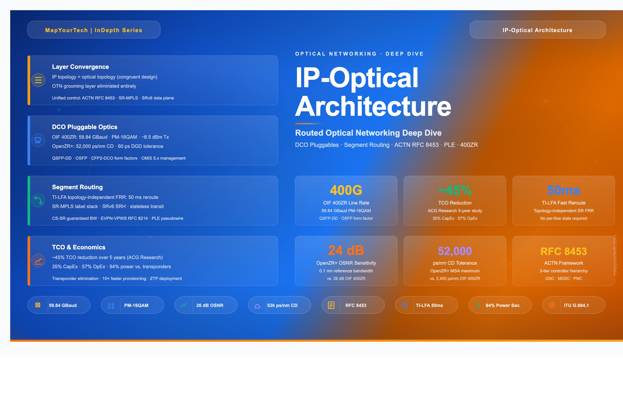
IP-Optical Communication
Network Architecture
A comprehensive engineering reference covering the convergence of IP/MPLS and DWDM optical transport, coherent pluggable technology, unified control plane architecture, and the shift to congruent IP-optical topologies — from traditional three-layer stacks to modern Routed Optical Networking.
1. Introduction
IP-Optical Communication Network Architecture describes the design discipline that tightly integrates Internet Protocol (IP) layer routing and switching with Dense Wavelength Division Multiplexing (DWDM) optical transport into a single, converged network plane. Where traditional designs stacked three fully independent technology layers — optical DWDM, Optical Transport Network (OTN) grooming, and IP/MPLS routing — each with its own management system, control plane, and operational team, the IP-Optical architecture collapses this complexity into one. The result is a network whose IP routing topology mirrors the underlying physical fiber topology, rather than operating as an overlay with no awareness of the optical layer beneath it.
The architectural transition is not cosmetic. It changes the fundamental way in which traffic is forwarded, wavelengths are allocated, failure is detected, and services are provisioned. It places coherent Digital Coherent Optics (DCO) pluggable modules directly into router line cards, eliminating the external transponder and muxponder equipment that previously sat between routers and DWDM systems. Control is unified through the IETF's Abstraction and Control of Traffic-Engineered Networks (ACTN) framework, standardized in RFC 8453, which defines how a hierarchical controller can orchestrate both IP and optical domains from a single northbound interface.
This guide covers the full engineering scope of IP-Optical architecture: the legacy pain points that motivated it, the core technologies that make it work, the architecture of its control and data planes, deployment topology options, a practical OSNR-based worked example, service convergence mechanisms including Private Line Emulation (PLE), and the operational and economic case for migration. Engineers who complete this reference will be equipped to evaluate, design, and operate IP-Optical networks in service provider, enterprise backbone, and data center interconnect environments.
2. Why IP-Optical Architecture Is Needed
"The network that got us here won't get us there." This observation, widely circulated at industry forums, captures the economic inflection point that service providers reached in the 2010s. Traffic volumes grew at compound annual rates exceeding 30%, driven by video streaming, cloud services, and mobile broadband. Capital expenditure, however, could not scale at the same pace — the ratio of revenue per bit transported declined faster than infrastructure costs fell. Something in the architecture had to change.
The root of the problem lay in the inherited three-layer model. DWDM systems multiplexed wavelengths onto fiber, OTN equipment groomed and switched sub-wavelength circuits, and IP/MPLS routers handled packet forwarding. Each layer was engineered, procured, operated, and maintained by a different team using a different management system. A single new service might require coordinated provisioning actions across all three systems — a process that often took days or weeks. When a fiber cut occurred, three separate restoration processes ran in parallel, frequently interfering with one another and extending mean time to repair.
Network utilization suffered for structural reasons, not operational ones. Because the IP routing topology did not match the fiber topology, traffic between two adjacent sites would often traverse multiple intermediate nodes at the optical layer before appearing as an IP adjacency. This created artificially long wavelength paths, forced lower baud-rate modulation formats, and consumed optical spectrum that could otherwise carry higher-capacity channels. A site with three physically adjacent neighbors might appear, at the IP layer, as if it had only two, because the third adjacency required an indirect wavelength route through a distant ROADM.
Read the Full Analysis with Premium
The remaining 89% of this article — the design numbers, trade-offs and field guidance — is part of MapYourTech Premium, along with the full premium library, courses and professional tools.
You May Also Like

-
Free
-
September 4, 2026

-
Premium
-
September 4, 2026

-
Premium
-
September 4, 2026