HomeAnalysisOptical Network Architecture and Use Cases
Last Updated: May 16, 2026
44 min read
188
Optical Network Architecture and Use Cases
MapYourTech InDepth Series
Optical Network Architecture and Use Cases
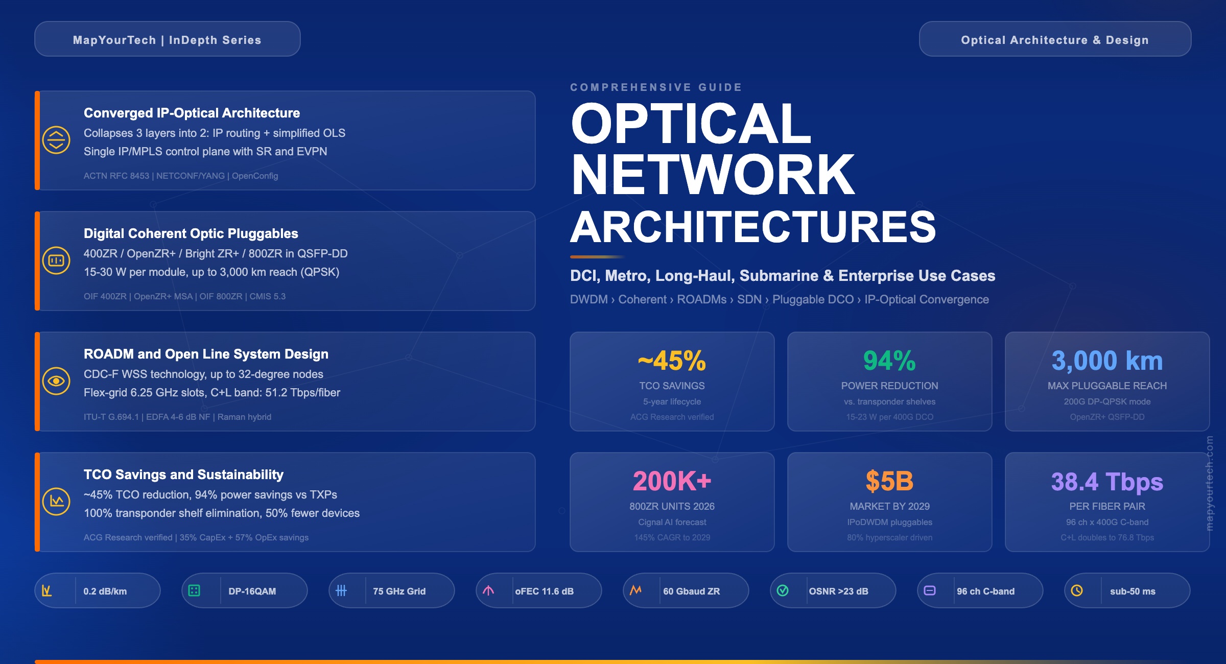
A comprehensive guide to modern optical network design: from legacy layered architectures to converged IP-optical networks, covering DWDM, coherent pluggable optics, ROADMs, automation frameworks, and real-world deployment across metro, long-haul, submarine, and data center domains.
"The network is not just a collection of pipes; it is the nervous system of the digital economy. How you architect its optical layer determines everything above it."
- Dr. Andrew Chraplyvy, Bell Labs Pioneer in Optical Fiber Transmission
Optical network architecture defines the structural design and interconnection strategy that determines how light-based signals carry data across fiber-optic infrastructure. It encompasses the physical layer (fibers, amplifiers, ROADMs), the transport layer (framing, multiplexing, switching), and the control and management planes that automate provisioning, protection, and performance monitoring. As of 2026, optical networks carry more than 99% of all intercontinental data traffic and form the backbone of every major service provider, hyperscaler, and enterprise wide-area network.
The architectural decisions in an optical network directly affect capacity, reach, cost, resilience, and operational agility. A metro ring with 96 DWDM channels at 400 Gbps per channel delivers 38.4 Tbps of aggregate capacity over a single fiber pair. A long-haul backbone using coherent 800G pluggable optics over amplified spans of 80 km can reach distances exceeding 1,000 km without optical-electrical-optical (OEO) regeneration. These real-world numbers are not theoretical maxima but deployed, production-verified capabilities.
This guide covers the complete landscape of optical network architecture: the legacy layered model and its pain points, the evolution toward converged IP-optical designs, the building blocks of modern DWDM systems (coherent optics, ROADMs, amplifiers, Digital Signal Processing), the automation and control frameworks (NETCONF/YANG, OpenConfig, hierarchical SDN controllers), and the deployment use cases spanning campus, metro, regional, long-haul, submarine, and data center interconnect. Every concept is grounded in verifiable specifications and real deployment scenarios.
2. Why Optical Network Architecture Needed to Evolve
"You can't solve tomorrow's bandwidth problem by adding another layer to yesterday's architecture."
- Industry Architect Perspective
Traditional optical transport networks were built as rigid, multi-layered stacks. The router forwarded IP packets over grey (short-reach) optics to an Optical Transport Network (OTN) switch, which groomed traffic into OTU-4 (100G) or OTUCn containers. The OTN switch then handed the signal to an external transponder (or muxponder), which performed the conversion from grey client signals to colored DWDM wavelengths. Those wavelengths entered a Reconfigurable Optical Add/Drop Multiplexer (ROADM) mesh for transport across the photonic layer. Each of these three layers — IP routing, OTN switching, and DWDM transport — operated with its own management system, control plane, and operations team.
This model created multiple operational challenges. First, three separate control planes needed coordination: IP/MPLS for the packet layer, GMPLS for OTN, and WSON/SSON (Wavelength/Spectrum Switched Optical Network) for the DWDM layer. Second, each layer had its own Element Management System (EMS) and Network Management System (NMS), forcing operators to maintain three independent toolchains for service provisioning, fault management, and performance monitoring. Third, adding new capacity required coordinated truck rolls and change windows across all three layers, stretching service activation times from hours to weeks.
The transponder shelf itself was a major cost and power burden. A single 100G transponder chassis consumed approximately 150 W per 100 Gbps of transported capacity. For a large service provider deploying 10,000 wavelengths, transponder shelves alone accounted for 1.5 MW of power and thousands of rack units of space. Each transponder also required grey optic interconnects to the router, adding fiber patch panels, intermediate distribution frames, and additional failure points. Industry studies showed that transponder-related costs (hardware, power, cooling, space, spares) represented 30–40% of the total optical network capital expenditure.
Protection and restoration added further complexity. The DWDM layer provided optical restoration via WSON/SSON with 1+R (restoration) or 1+1+R (protection plus restoration) schemes. The OTN layer offered ODU-level protection. The IP/MPLS layer ran its own Fast Reroute (FRR) and Traffic Engineering (TE) mechanisms. These three independent protection domains often conflicted, creating race conditions where multiple layers simultaneously rerouted traffic in response to a single fiber cut. The result was unpredictable convergence behavior and wasted bandwidth reserved for redundant protection at each layer.
Figure 1: Traditional multi-layer architecture (left) requires three independent control planes, management systems, and operations teams. The converged IP-optical architecture (right) collapses these into a single IP routing layer with integrated coherent optics and a simplified optical line system, managed through a unified hierarchical SDN controller.
Premium Article — Free 11% Preview
Read the Full Analysis with Premium
The remaining 89% of this article — the design numbers, trade-offs and field guidance — is part of MapYourTech Premium, along with the full premium library, courses and professional tools.
The full Premium Pro library, unlocked with one click. The clock starts the moment you check out and runs for 3 full hours - pick a time when you can make the most of it.