
HomePosts tagged “Channel spacing”
Channel spacing
Showing 1 - 4 of 4 results
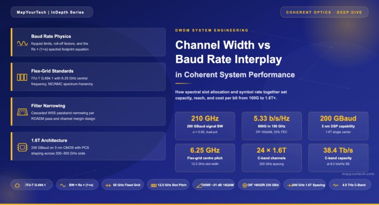
Channel Width vs Baud Rate Interplay in System Performance Skip to main content MapYourTech | InDepth Series Channel Width vs...
-
Free
-
April 22, 2026
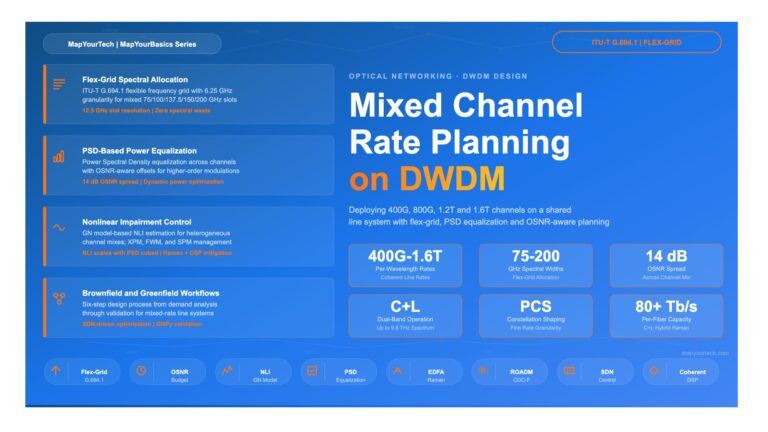
Mixed Channel Rate Planning on DWDM Line Systems Mixed Channel Rate Planning on DWDM Line Systems A Design Engineer’s Guide...
-
Free
-
March 21, 2026
Introduction The telecommunications industry constantly strives to maximize the use of fiber optic capacity. Despite the broad spectral width of...
-
Free
-
March 26, 2025
In a non-coherent WDM system, each optical channel on the line side uses only one binary channel to carry service information. The service transmission...
-
Free
-
March 26, 2025
Explore Articles
- Analysis
- Automation
- Careers and Learning Paths
- Coherent Optics
- Data Center Interconnect
- Free
- Fundamentals
- Management
- Network Architecture
- Planning & Design
- Premium
- Professional Development
- Security
- Standards
- Submarine and Long-Haul
- Technical
- Testing
- Tools and Simulators
- Trends & News
- Troubleshooting and Operations
- Vendor and Product Landscape
Filter Articles
ResetExplore Courses
Tags
400ZR
automation
behavioral
behavioral interview
ber
candidate
career
COHERENT
coherent optical transmission
coherent optics
data center interconnect
Data transmission
DWDM
edfa
EDFA noise figure
Fiber optics
Fiber optic technology
Forward Error Correction
hiring
Interview
Latency
modulation
network automation
noise figure
optical
Optical communication
Optical fiber
Optical network
optical network automation
optical networking
Optical signal-to-noise ratio
OSNR
OSNR calculation
OTN
preparation
Probabilistic Constellation Shaping
Q-factor
recruiter
ROADM
Signal quality
Slider
spectral efficiency
STAR
submarine
Ticker