Tag

Fiber Optic Communication

Browsing

In the world of fiber-optic communication, the integrity of the transmitted signal is critical. As an optical engineers, our primary objective is to mitigate the attenuation of signals across long distances, ensuring that data arrives at its destination with minimal loss and distortion. In this article we will discuss into the challenges of linear and nonlinear degradations in fiber-optic systems, with a focus on transoceanic length systems, and offers strategies for optimising system performance.

The Role of Optical Amplifiers

Erbium-doped fiber amplifiers (EDFAs) are the cornerstone of long-distance fiber-optic transmission, providing essential gain within the low-loss window around 1550 nm. Positioned typically between 50 to 100 km apart, these amplifiers are critical for compensating the fiber’s inherent attenuation. Despite their crucial role, EDFAs introduce additional noise, progressively degrading the optical signal-to-noise ratio (OSNR) along the transmission line. This degradation necessitates a careful balance between signal amplification and noise management to maintain transmission quality.

OSNR: The Critical Metric

The received OSNR, a key metric for assessing channel performance, is influenced by several factors, including the channel’s fiber launch power, span loss, and the noise figure (NF) of the EDFA. The relationship is outlined as follows:

osnrformula

Where:

  • is the number of EDFAs the signal has passed through.
  •  is the power of the signal when it’s first sent into the fiber, in dBm.
  • Loss represents the total loss the signal experiences, in dB.
  • NF is the noise figure of the EDFA, also in dB.

Increasing the launch power enhances the OSNR linearly; however, this is constrained by the onset of fiber nonlinearity, particularly Kerr effects, which limit the maximum effective launch power.

The Kerr Effect and Its Implications

The Kerr effect, stemming from the intensity-dependent refractive index of optical fiber, leads to modulation in the fiber’s refractive index and subsequent optical phase changes. Despite the Kerr coefficient () being exceedingly small, the combined effect of long transmission distances, high total power from EDFAs, and the small effective area of standard single-mode fiber (SMF) renders this nonlinearity a dominant factor in signal degradation over transoceanic distances.

The phase change induced by this effect depends on a few key factors:

  • The fiber’s nonlinear coefficient .
  • The signal power , which varies over time.
  • The transmission distance.
  • The fiber’s effective area .

kerr

This phase modulation complicates the accurate recovery of the transmitted optical field, thus limiting the achievable performance of undersea fiber-optic transmission systems.

The Kerr effect is a bit like trying to talk to someone at a party where the music volume keeps changing. Sometimes your message gets through loud and clear, and other times it’s garbled by the fluctuations. In fiber optics, managing these fluctuations is crucial for maintaining signal integrity over long distances.

Striking the Right Balance

Understanding and mitigating the effects of both linear and nonlinear degradations are critical for optimising the performance of undersea fiber-optic transmission systems. Engineers must navigate the delicate balance between maximizing OSNR for enhanced signal quality and minimising the impact of nonlinear distortions.The trick, then, is to find that sweet spot where our OSNR is high enough to ensure quality transmission but not so high that we’re deep into the realm of diminishing returns due to nonlinear degradation. Strategies such as carefully managing launch power, employing advanced modulation formats, and leveraging digital signal processing techniques are vital for overcoming these challenges.


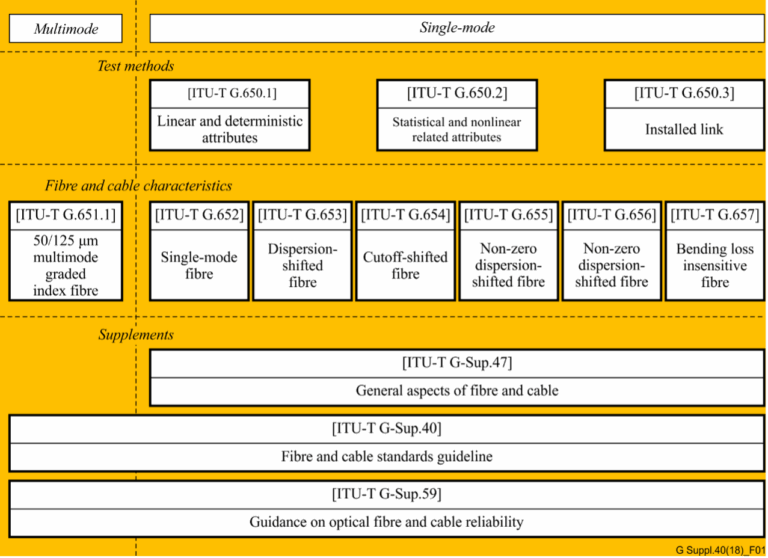
In the realm of telecommunications, the precision and reliability of optical fibers and cables are paramount. The International Telecommunication Union (ITU) plays a crucial role in this by providing a series of recommendations that serve as global standards. The ITU-T G.650.x and G.65x series of recommendations are especially significant for professionals in the field. In this article, we delve into these recommendations and their interrelationships, as illustrated in Figure 1 .

ITU-T G.650.x Series: Definitions and Test Methods

#opticalfiber

The ITU-T G.650.x series is foundational for understanding single-mode fibers and cables. ITU-T G.650.1 is the cornerstone, offering definitions and test methods for linear and deterministic parameters of single-mode fibers. This includes key measurements like attenuation and chromatic dispersion, which are critical for ensuring fiber performance over long distances.

Moving forward, ITU-T G.650.2 expands on the initial parameters by providing definitions and test methods for statistical and non-linear parameters. These are essential for predicting fiber behavior under varying signal powers and during different transmission phenomena.

For those involved in assessing installed fiber links, ITU-T G.650.3 offers valuable test methods. It’s tailored to the needs of field technicians and engineers who analyze the performance of installed single-mode fiber cable links, ensuring that they meet the necessary standards for data transmission.

ITU-T G.65x Series: Specifications for Fibers and Cables

The ITU-T G.65x series recommendations provide specifications for different types of optical fibers and cables. ITU-T G.651.1 targets the optical access network with specifications for 50/125 µm multimode fiber and cable, which are widely used in local area networks and data centers due to their ability to support high data rates over short distances.

The series then progresses through various single-mode fiber specifications:

  • ITU-T G.652: The standard single-mode fiber, suitable for a wide range of applications.
  • ITU-T G.653: Dispersion-shifted fibers optimized for minimizing chromatic dispersion.
  • ITU-T G.654: Features a cut-off shifted fiber, often used for submarine cable systems.
  • ITU-T G.655: Non-zero dispersion-shifted fibers, which are ideal for long-haul transmissions.
  • ITU-T G.656: Fibers designed for a broader range of wavelengths, expanding the capabilities of dense wavelength division multiplexing systems.
  • ITU-T G.657: Bending loss insensitive fibers, offering robust performance in tight bends and corners.

Historical Context and Current References

It’s noteworthy to mention that the multimode fiber test methods were initially described in ITU-T G.651. However, this recommendation was deleted in 2008, and now the test methods for multimode fibers are referenced in existing IEC documents. Professionals seeking current standards for multimode fiber testing should refer to these IEC documents for the latest guidelines.

Conclusion

The ITU-T recommendations play a critical role in the standardization and performance optimization of optical fibers and cables. By adhering to these standards, industry professionals can ensure compatibility, efficiency, and reliability in fiber optic networks. Whether you are a network designer, a field technician, or an optical fiber manufacturer, understanding these recommendations is crucial for maintaining the high standards expected in today’s telecommunication landscape.

Reference

https://www.itu.int/rec/T-REC-G/e

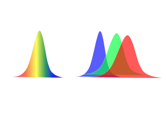
Chromatic dispersion affects all optical transmissions to some degree.These effects become more pronounced as the transmission rate increases and fiber length increases. 

Factors contributing to increasing chromatic dispersion signal distortion include the following:

1. Laser spectral width, modulation method, and frequency  chirp. Lasers with wider spectral widths and chirp have shorter dispersion limits. It is important to refer to manufacturer specifications to determine the total amount of dispersion that can be tolerated by the lightwave equipment.

2. The wavelength of the optical signal. Chromatic dispersion varies with wavelength in a fiber. In a standard non-dispersion shifted fiber (NDSF G.652), chromatic dispersion is near or at zero at 1310 nm. It increases positively with increasing wavelength and increases negatively for wavelengths less than 1310 nm.

3. The optical bit rate of the transmission laser. The higher the fiber bit rate, the greater the signal distortion effect.
4. The chromatic dispersion characteristics of fiber used in the link. Different types of fiber have different dispersion characteristics.
5. The total fiber link length, since the effect is cumulative along the length of the fiber.
6. Any other devices in the link that can change the link’s total chromatic dispersion including chromatic dispersion compensation modules.
7. Temperature changes of the fiber or fiber cable can cause small changes to chromatic dispersion. Refer to the manufacturer’s fiber cable specifications for values.

Methods to Combat Link Chromatic Dispersion

1. Change the equipment laser with a laser that has a specified longer dispersion limit. This is typically a laser with a more narrow spectral width or a laser that has some form of precompensation. As laser spectral width decreases, chromatic dispersion limit increases.
2. For new construction, deploy NZ-DSF instead of SSMF fiber.NZ-DSF has a lower chromatic dispersion specification.
3. Insert chromatic dispersion compensation modules (DCM) into the fiber link to compensate for the excessive dispersion. The optical loss of the DCM must be added to the link optical loss budget and optical amplifiers may be required to compensate.
4. Deploy a 3R optical repeater (re-amplify, reshape, and retime the signal) once a link reaches chromatic dispersion equipment limit.
5. For long haul undersea fiber deployment, splicing in alternating lengths of dispersion compensating fiber can be considered.
6. To reduce chromatic dispersion variance due to temperature, buried cable is preferred over exposed aerial cable.