
HomePosts tagged “Fiber Optic Installation”
Fiber Optic Installation
Showing 1 - 3 of 3 results
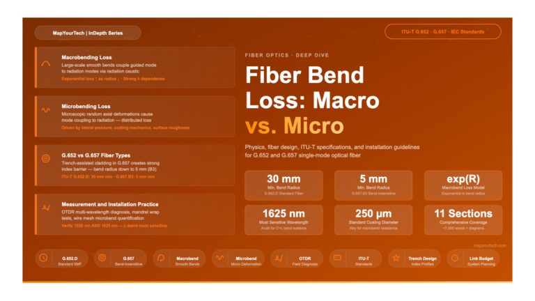
Fiber Bend Loss: Macrobend vs. Microbend — MapYourTech Fiber Bend Loss: Macrobend vs. Microbend Physics, fiber-type specifications, ITU-T standards, and...
-
Free
-
March 1, 2026
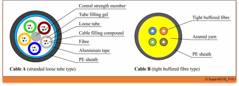
The world of optical communication is intricate, with different cable types designed for specific environments and applications. Today, we’re diving...
-
Free
-
March 26, 2025
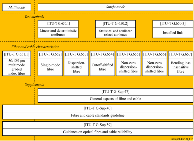
In the realm of telecommunications, the precision and reliability of optical fibers and cables are paramount. The International Telecommunication Union...
-
Free
-
March 26, 2025
Explore Articles
- Analysis
- Automation
- Careers and Learning Paths
- Coherent Optics
- Data Center Interconnect
- Free
- Fundamentals
- Management
- Network Architecture
- Planning & Design
- Premium
- Professional Development
- Security
- Standards
- Submarine and Long-Haul
- Technical
- Testing
- Tools and Simulators
- Trends & News
- Troubleshooting and Operations
- Vendor and Product Landscape
Filter Articles
ResetExplore Courses
Tags
400ZR
automation
behavioral
behavioral interview
ber
candidate
career
COHERENT
coherent optical transmission
coherent optics
data center interconnect
Data transmission
DWDM
edfa
EDFA noise figure
Fiber optics
Fiber optic technology
Forward Error Correction
hiring
Interview
Latency
modulation
network automation
noise figure
optical
Optical communication
Optical fiber
Optical network
optical network automation
optical networking
Optical signal-to-noise ratio
OSNR
OSNR calculation
OTN
preparation
Probabilistic Constellation Shaping
Q-factor
recruiter
ROADM
Signal quality
Slider
spectral efficiency
STAR
submarine
Ticker