Tag

High-Speed Networking

Browsing

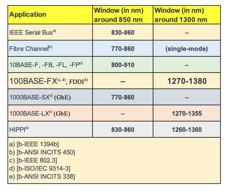
While single-mode fibers have been the mainstay for long-haul telecommunications, multimode fibers hold their own, especially in applications where short distance and high bandwidth are critical. Unlike their single-mode counterparts, multimode fibers are not restricted by cut-off wavelength considerations, offering unique advantages.

The Nature of Multimode Fibers

Multimode fibers, characterized by a larger core diameter compared to single-mode fibers, allow multiple light modes to propagate simultaneously. This results in modal dispersion, which can limit the distance over which the fiber can operate without significant signal degradation. However, multimode fibers exhibit greater tolerance to bending effects and typically showcase higher attenuation coefficients.

Wavelength Windows for Multimode Applications

Multimode fibers shine in certain “windows,” or wavelength ranges, which are optimized for specific applications and classifications. These windows are where the fiber performs best in terms of attenuation and bandwidth.

#multimodeband

IEEE Serial Bus (around 850 nm): Typically used in consumer electronics, the 830-860 nm window is optimal for IEEE 1394 (FireWire) connections, offering high-speed data transfer over relatively short distances.

Fiber Channel (around 770-860 nm): For high-speed data transfer networks, such as those used in storage area networks (SANs), the 770-860 nm window is often used, although it’s worth noting that some applications may use single-mode fibers.

Ethernet Variants:

  • 10BASE (800-910 nm): These standards define Ethernet implementations for local area networks, with 10BASE-F, -FB, -FL, and -FP operating within the 800-910 nm range.
  • 100BASE-FX (1270-1380 nm) and FDDI (Fiber Distributed Data Interface): Designed for local area networks, they utilize a wavelength window around 1300 nm, where multimode fibers offer reliable performance for data transmission.
  • 1000BASE-SX (770-860 nm) for Gigabit Ethernet (GbE): Optimized for high-speed Ethernet over multimode fiber, this application takes advantage of the lower window around 850 nm.
  • 1000BASE-LX (1270-1355 nm) for GbE: This standard extends the use of multimode fibers into the 1300 nm window for Gigabit Ethernet applications.

HIPPI (High-Performance Parallel Interface): This high-speed computer bus architecture utilizes both the 850 nm and the 1300 nm windows, spanning from 830-860 nm and 1260-1360 nm, respectively, to support fast data transfers over multimode fibers.

Future Classifications and Studies

The classification of multimode fibers is a subject of ongoing research. Proposals suggest the use of the region from 770 nm to 910 nm, which could open up new avenues for multimode fiber applications. As technology progresses, these classifications will continue to evolve, reflecting the dynamic nature of fiber optic communications.

Wrapping Up: The Place of Multimode Fibers in Networking

Multimode fibers are a vital part of the networking world, particularly in scenarios that require high data rates over shorter distances. Their resilience to bending and capacity for high bandwidth make them an attractive choice for a variety of applications, from high-speed data transfer in industrial settings to backbone cabling in data centers.

As we continue to study and refine the classifications of multimode fibers, their role in the future of networking is guaranteed to expand, bringing new possibilities to the realm of optical communications.

References

https://www.itu.int/rec/T-REC-G/e

Carrier Ethernet: A Formal Definition

The MEF (Metro Ethernet Forum)  has defined Carrier Ethernet as the “ubiquitous, standardized, Carrier-class service defined by five attributes that distinguish Carrier Ethernet from the familiar LAN based Ethernet.” As depicted in Figure , these five attributes, in no particular order, are

1. Standardized services  

•E-Line, E-LAN provide transparent, private line, virtual private line and LAN services
•A ubiquitous service providing globally & locally via standardized equipment
•Requires no changes to customer LAN equipment or networks and accommodates existing network connectivity such as, time-sensitive, TDM traffic and signaling
•Ideally suited to converged voice, video & data networks
•Wide choice and granularity of bandwidth and quality of service options

  2. Scalability

•The ability for millions to use a network service that is ideal for the widest variety of business, information, communications and entertainment applications with voice, video and data
•Spans Access & Metro to National & Global Services over a wide variety of physical infrastructures implemented by a wide range of Service Providers
•Scalability of bandwidth from 1Mbps to 10Gbps and beyond, in granular increments


3. Reliability

•The ability for the network to detect & recover from incidents without impacting users
•Meeting the most demanding quality and availability requirements
•Rapid recovery time when problems do occur, as low as 50ms

4. Quality of Service (QoS)

•Wide choice and granularity of bandwidth and quality of service options
•Service Level Agreements (SLAs) that deliver end-to-end performance matching the requirements for voice, video and data over converged business and residential networks
•Provisioning via SLAs  that provide end-to-end performance based on CIR, frame loss, delay and delay variation characteristics

5. Service management

•The ability to monitor, diagnose and centrally manage the network, using standards-based vendor independent implementations
•Carrier-class OAM
•Rapid service provisioning


What is Carrier Ethernet?

Carrier Ethernet essentially augments traditional Ethernet, optimized for LAN deployment,with Carrier-class capabilities which make it optimal for deployment in Service Provider Access/Metro Area Networks and beyond, to the Wide Area Network. And conversely,from an end-user (enterprise) standpoint, Carrier Ethernet is a service that not only provides a standard Ethernet (or for that matter, a standardized non-Ethernethand-off  but also provides the robustness, deterministic performance, management, and flexibility expected of Carrier-class services.

Carrier Ethernet Architecture


Data moves from UNI to UNI across “the network” with a layered architecture.

When traffic moves between ETH domains is does so at the TRAN layer. This allows  Carrier Ethernet traffic to be
agnostic to the networks that it traverses

ce


ce1

MEF Carrier Ethernet Terminology

•The User Network Interface (UNI)
–The UNI is always provided by the Service Provider
–The UNI in a Carrier Ethernet Network is a physical Ethernet Interface at operating speeds 10Mbs, 100Mbps, 1Gbps or 10Gbps
•Ethernet Virtual Connection (EVC)
–Service container
–Connects two or more subscriber sites (UNI’s)
–An association of two or more UNIs
–Prevents data transfer between sites that are not part of the same EVC
–Three types of EVCs
•Point-to-Point
•Multipoint-to-Multipoint
•Rooted Multipoint
–Can be bundled or multiplexed on the same UNI
–Defined in MEF 10.2 technical specification
Carrier Ethernet Terminology
•UNI Type I
–A UNI compliant with MEF 13
–Manually Configurable
•UNI Type II
–Supports E-Tree
–Support service OAM, link protection
–Automatically Configurable via E-LMI
–Manageable via OAM
•Network to Network Interface (NNI)
–Network to Network Interface between distinct MEN operated by one or more carriers
–An active project of the MEF
•Metro Ethernet Network (MEN)
–An Ethernet transport network connecting user end-points
(Expanded to Access and Global networks in addition to the original Metro Network meaning)

Carrier Ethernet Service Types

ce3
Services Using E-Line Service Type

Ethernet Private Line (EPL)

•Replaces a TDM Private line
•Port-based service with single service (EVC) across dedicated UNIs providing site-to-site connectivity
•Typically delivered over SDH (Ethernet over SDH)
•Most popular Ethernet service due to its simplicity

Ethernet Virtual Private Line (EVPL)

•Replaces Frame Relay or ATM L2 VPN services
–To deliver higher bandwidth, end-to-end services
•Enables multiple services (EVCs) to be delivered over  single physical connection (UNI) to customer premises
•Supports “hub & spoke” connectivity via Service Multiplexed UNI at hub site
–Similar to Frame Relay or Private Line hub and spoke deployments
Services Using E-LAN Service Type
•EP-LAN: Each UNI dedicated to the EP-LAN service. Example use is Transparent LAN
•EVP-LAN: Service Multiplexing allowed at each UNI. Example use is Internet access and corporate VPN via one UNI

Services Using E-Tree Service Type

EP-Tree and EVP-Tree:  Both allow root – root and root – leaf communication but not leaf – leaf communication.

•EP-Tree requires dedication of the UNIs to the single EP-Tree service
•EVP-Tree allows each UNI to be support multiple simultaneous services at the cost of more complex configuration that EP-Tree

APPLICATION OF CARRIER ETHERNET


The Standardization of Services: Approved MEF Specifications

•MEF 2   Requirements and Framework for Ethernet Service Protection
•MEF 3  Circuit Emulation Service Definitions, Framework and Requirements in Metro Ethernet Networks
•MEF 4   Metro Ethernet Network Architecture Framework
Part 1: Generic Framework
•MEF 6  Metro Ethernet Services Definitions Phase I
•MEF 7   EMS-NMS Information Model
•MEF 8  Implementation Agreement for the Emulation of PDH Circuits over Metro Ethernet Networks
•MEF 9   Abstract Test Suite for Ethernet Services at the UNI
•MEF 10   Ethernet Services Attributes Phase I
•MEF 11   User Network Interface (UNI) Requirements and Framework
•MEF 12  Metro Ethernet Network Architecture Framework
Part 2: Ethernet Services Layer
•MEF 13   User Network Interface (UNI) Type 1 Implementation Agreement
•MEF 14   Abstract Test Suite for Traffic Management Phase 1
•MEF 15  Requirements for Management of Metro Ethernet
Phase 1 Network Elements
•MEF 16   Ethernet Local Management Interface

How the MEF Specifications Enable Carrier Ethernet