
HomePosts tagged “Optical transmission”
Optical transmission
Showing 1 - 4 of 4 results
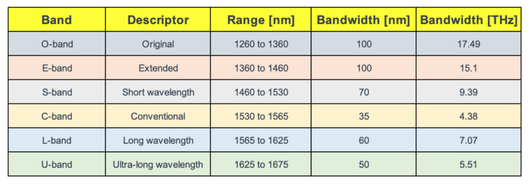
When we talk about the internet and data, what often comes to mind are the speeds and how quickly we...
-
Free
-
March 26, 2025
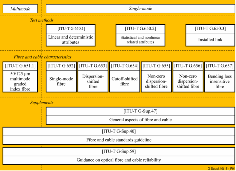
In the realm of telecommunications, the precision and reliability of optical fibers and cables are paramount. The International Telecommunication Union...
-
Free
-
March 26, 2025
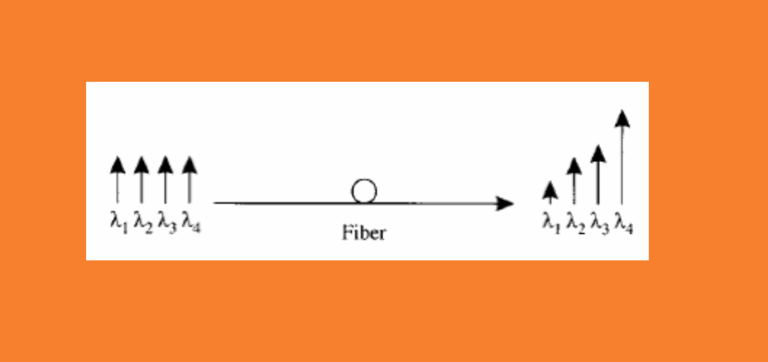
When the bit error occurs to the system, generally the OSNR at the transmit end is well and the fault...
-
Free
-
March 26, 2025
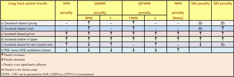
Non-linear interactions between the signal and the silica fibre transmission medium begin to appear as optical signal powers are increased...
-
Free
-
March 26, 2025
Explore Articles
- Analysis
- Automation
- Careers and Learning Paths
- Coherent Optics
- Data Center Interconnect
- Free
- Fundamentals
- Management
- Network Architecture
- Planning & Design
- Premium
- Professional Development
- Security
- Standards
- Submarine and Long-Haul
- Technical
- Testing
- Tools and Simulators
- Trends & News
- Troubleshooting and Operations
- Vendor and Product Landscape
Filter Articles
ResetExplore Courses
Tags
400ZR
automation
behavioral
behavioral interview
ber
candidate
career
COHERENT
coherent optical transmission
coherent optics
data center interconnect
Data transmission
DWDM
edfa
EDFA noise figure
Fiber optics
Fiber optic technology
Forward Error Correction
hiring
Interview
Latency
modulation
network automation
noise figure
optical
Optical communication
Optical fiber
Optical network
optical network automation
optical networking
Optical signal-to-noise ratio
OSNR
OSNR calculation
OTN
preparation
Probabilistic Constellation Shaping
Q-factor
recruiter
ROADM
Signal quality
Slider
spectral efficiency
STAR
submarine
Ticker