The Clean-Fiber Zone in Raman Links:
Why the First 20 km Near the Pump Must Be Connector-Free
1 Introduction
When a Raman amplified link is commissioned on an existing fiber route, one of the first checks an engineer performs is an audit of the fiber plant in the zone closest to the pump injection point. Any mechanical connectors — patch panels, in-line adapters, field-installed connectors — found within roughly 20 to 25 km of the pump unit are flagged for replacement with fusion splices before the Raman system is allowed to go live. This requirement surprises many engineers who are accustomed to treating connectors as routine, low-risk components in standard EDFA-based links.
The reason is not arbitrary. Raman amplification works by injecting a high-power CW laser (the pump) directly into the transmission fiber. Unlike an EDFA, where amplification happens in a separate erbium-doped fiber element, a Raman amplifier uses the span fiber itself as the gain medium. The pump travels backward through the same fiber that carries the live signal traffic. In a backward-pumped system, the pump enters at the receive end and propagates toward the transmit end, losing power with every kilometer due to fiber attenuation. Near the injection point — before significant decay has occurred — pump power can reach 300 mW to more than 1 W in the fiber. At these levels, connectors introduce three distinct failure mechanisms that either permanently damage equipment, degrade signal quality below acceptable thresholds, or create safety hazards. Understanding each mechanism quantitatively is essential for anyone designing, commissioning, or maintaining a Raman-amplified network.
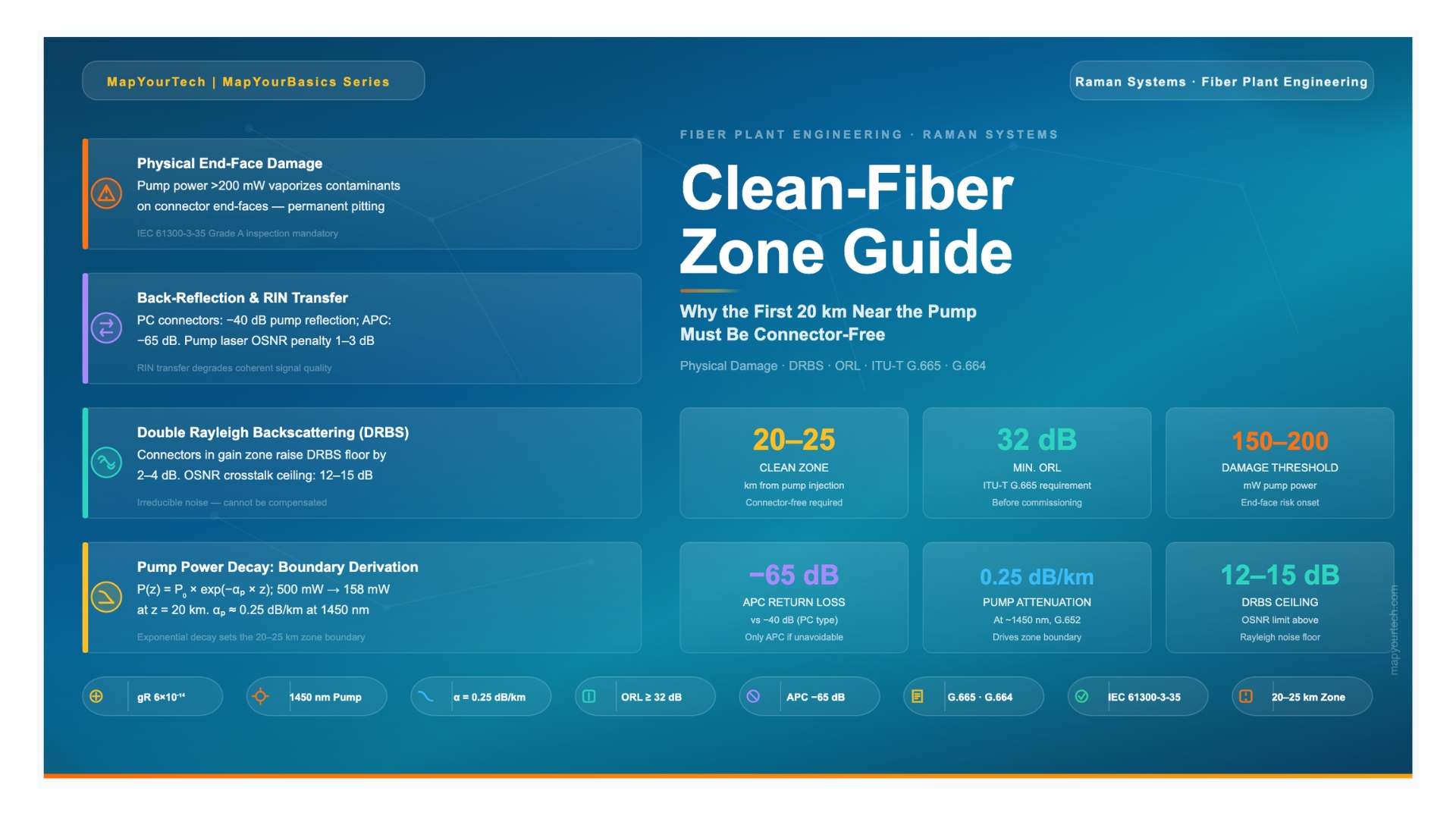
Takeaway: The clean-fiber zone requirement is not a vendor-specific precaution — it follows directly from the physics of high-power pump propagation in the fiber and is governed by ITU-T G.665 and G.664. Connectors within 20–25 km of a Raman pump injection point create risks of physical end-face damage, pump laser destabilization through back-reflection, and elevated double Rayleigh backscattering noise that cannot be mitigated after installation.
Continue Reading This Article
Sign in with a free account to unlock the full article and access the complete MapYourTech knowledge base.
2 Raman Pump Architecture and Power Levels
2.1 Backward-Pumped Configuration
The dominant configuration in deployed Raman systems is backward (counter-propagating) pumping. The pump laser is co-located with the optical line terminal or amplifier site at the far (receive) end of the span. The pump light enters the fiber at this far end and travels in the opposite direction to the signal. Counter-propagation minimizes the transfer of pump relative intensity noise (RIN) onto the signal — because the pump and signal are never co-propagating over the same fiber length at the same time, the correlation between pump fluctuations and signal fluctuations is averaged out over the span length.
Forward pumping (co-propagating with the signal) offers higher Raman gain efficiency per unit pump power because the pump and signal interact over a longer effective length near the transmit end where signal power is highest. However, forward pumping transfers pump RIN directly onto the signal at the same time and over the same fiber segment, leading to significant OSNR penalties at baud rates above roughly 10 Gbaud. For these reasons, most production Raman deployments use either backward-only pumping or a hybrid approach where the majority of pump power is backward-propagating.
2.2 Pump Power Levels in Practice
A single-wavelength Raman pump module typically outputs between 150 mW and 500 mW (+21.8 to +27 dBm) at wavelengths in the 1420–1510 nm range for C-band amplification, or 1480–1520 nm for L-band. To achieve sufficient net gain (typically 3–10 dB depending on span length and design), multiple pump wavelengths are often combined using a WDM coupler. A two-pump system might inject 400 mW per wavelength, for a combined in-fiber power of 800 mW to 1 W (+29 to +30 dBm). Ultra-long-haul designs for 100+ km spans may push total pump power above 1.5 W (+31.8 dBm).
These power levels are orders of magnitude higher than the signal powers present in the fiber (typically −3 to +3 dBm per channel at the transmitter). The high pump power is necessary because Raman gain requires the pump to overcome both the distributed attenuation of the pump itself as it propagates along the span and the threshold set by the low Raman gain coefficient (gR ≈ 6 × 10⁻¹⁴ m/W for standard G.652 fiber). However, these same power levels mean that mechanical connectors encountered by the pump in the first 20–25 km — before significant attenuation has reduced pump power to safer levels — become points of serious concern.
Figure 1: Backward-pumped Raman span showing the clean-fiber zone (shaded, 0–20 km from pump injection point). Mechanical connectors within this zone are forbidden; only fusion splices are permitted. Pump power decay is shown as a curve above the fiber. Distance scale is from the transmitter end.
3 Physical Damage at Connector End-Faces
3.1 The Contamination-Damage Cycle
A standard optical fiber connector end-face, even when cleaned to IEC 61300-3-35 Grade A, carries surface contamination at a microscopic level — dust particles, hydrocarbon films, polishing residue. Under normal signal power conditions (−10 to +3 dBm), these contaminants absorb negligible optical energy. At Raman pump power levels exceeding 200 mW, the same microscopic particle absorbs enough optical energy to heat explosively. The phenomenon is called contamination-induced damage or, in severe cases, fiber fuse initiation.
The mechanism operates as follows: a particle on the end-face absorbs a fraction of the incident optical power and converts it to heat. For a sufficiently energetic pump, the particle temperature exceeds the glass softening point (approximately 1600 °C for silica) in microseconds. The softened glass and vaporized contaminant ablate the end-face surface, creating a permanent pit. The ablation products — carbon soot, silica particles, metal oxides from ferrule material — are ejected across the mating face, contaminating the opposing fiber end. The damage is permanent, non-recoverable without re-polishing the ferrule, and may propagate down the fiber as a moving thermal front (fiber fuse) in extreme cases where pump power exceeds approximately 1–2 W in the fiber core.
Beyond end-face pitting, mechanical connectors introduce an air gap between the two fiber end-faces. Even a perfect APC connector with zero contamination presents a glass-air-glass interface. Fresnel reflection at each glass-air interface is approximately −14.7 dB at normal incidence (refractive index n ≈ 1.46). In the context of hundreds of milliwatts of pump power, −14.7 dB of back-reflection corresponds to approximately 17 mW propagating back toward the pump laser — an amount sufficient to destabilize most Fabry-Perot and DFB laser sources unless they are equipped with strong optical isolation.
3.2 Power Thresholds and IEC Standards
IEC 61300-3-35 defines fiber optic connector end-face geometry and cleanliness inspection criteria. Grade A (the highest cleanliness grade) requires the core zone (0–25 µm radius) to be completely free of scratches and defects, with no particles greater than 2 µm in the contact zone. Grade B permits particles up to 5 µm in the contact zone and scratches up to 2 µm in the cladding. For Raman pump wavelengths (1420–1510 nm) and power levels above 200 mW, even Grade B end-faces are considered unsafe because the higher absorption coefficient of the ferrule substrate material at pump wavelengths, combined with the tighter mode field diameter at shorter wavelengths (∼7.5 µm at 1450 nm versus ∼9.2 µm at 1550 nm), intensifies the energy density at the contact zone.
Field Engineering Note
Do not assume that a connector passing Grade A inspection at 1550 nm signal wavelengths is safe for Raman pump exposure. Pump wavelengths (1420–1510 nm) have a smaller mode field diameter and higher absorption in common contaminants. A connector that passes Grade A visual inspection must still be eliminated from the clean-fiber zone and replaced with a low-loss fusion splice (target splice loss < 0.05 dB). If a connector must be retained (e.g., at a repeater housing transition), use only APC-type with fresh inspection, and document it in the ORL measurement baseline.
4 Back-Reflection and Pump Laser Instability
4.1 Discrete Reflections and Optical Return Loss
Optical return loss (ORL) is the total ratio of incident optical power to the sum of all reflected power returning to the source. For a fiber span containing multiple reflection points — connectors, splices, Rayleigh backscattering — the total back-reflected power is the incoherent sum of all individual reflections. ORL is expressed in dB as a positive quantity where higher values indicate less reflection:
While 50 µW may seem negligible, it is not so when it re-enters the pump laser cavity. A DFB or Fabry-Perot laser source typically requires an optical isolator providing 30–40 dB isolation to remain stable. The isolator reduces the 50 µW by a factor of 1000–10000, bringing the residual back into the laser to below 0.05 µW — borderline acceptable. A second connector in the zone adds another independent reflection event. Two connectors at −40 dB each produce −37 dB combined return, raising the reflected power to ≈ 100 µW and potentially pushing the pump laser past its isolation margin.
4.2 RIN Transfer and OSNR Degradation
When a reflected optical signal re-enters the pump laser cavity, it modulates the laser's emission by beating with the intracavity field. This interaction converts the laser's coherent noise (phase noise) into intensity noise, increasing the pump's relative intensity noise (RIN) spectral density. The modified pump RIN is then transferred onto the Raman-amplified signal through the gain mechanism — specifically, since backward-pumped Raman gain is not instantaneous but occurs over the full span length, the pump RIN couples to signal intensity as a function of the pump-signal walk-off. For typical backward-pumped links, pump RIN at frequencies below ∼10 MHz is suppressed by the distributed nature of the gain. However, enhanced pump RIN at resonance frequencies of the pump laser (typically 1–5 GHz for common Fabry-Perot sources) can bypass this averaging and add directly to signal RIN, degrading OSNR by 1–3 dB in severe cases.
5 Double Rayleigh Backscattering and the DRBS Floor
5.1 The DRBS Mechanism
Rayleigh backscattering is a fundamental property of silica fiber. At any point along the fiber, a fraction of the propagating optical power is scattered in the backward direction due to density and composition fluctuations in the glass. The Rayleigh backscatter coefficient for standard G.652 fiber is approximately −32 to −33 dB per meter of fiber length at 1550 nm. This distributed backscatter is normally harmless because it is spectrally indistinguishable from the signal but far below it in power.
In a Raman-amplified link, the problem arises when double Rayleigh backscattering (DRBS) occurs. The sequence is: (1) forward-propagating signal scatters backward at some point z1; (2) the backward-scattered signal propagates toward the transmitter, where it scatters again at point z2 and is re-directed forward; (3) this twice-scattered component, now co-propagating with the original signal, arrives at the receiver as crosstalk noise — at the same wavelength, indistinguishable from the signal. Raman gain amplifies this DRBS component in the same way it amplifies the signal, and since DRBS is spectrally coincident with the signal, it creates an irreducible crosstalk noise floor.
5.2 How Connectors Worsen the DRBS Floor
Mechanical connectors in the high-pump-power zone act as strong discrete back-reflection points. A single connector provides a reflection coefficient orders of magnitude larger than the distributed Rayleigh backscatter at any individual point in the fiber. When this discrete reflection occurs inside the Raman gain region (the high-pump-power zone), the reflected pump or signal component is re-amplified as it propagates forward again, increasing the effective DRBS contribution from that location by a factor equal to the Raman gain experienced over the remaining span length. The net effect is that a single connector in the clean-fiber zone can raise the DRBS crosstalk floor by several decibels, reducing the maximum achievable OSNR. The theoretical DRBS-limited OSNR ceiling for backward-pumped Raman links is approximately 12–15 dB above the distributed Rayleigh floor — connectors in the gain zone erode this margin.
Takeaway: Double Rayleigh backscattering sets a hard limit on the achievable OSNR in any Raman-amplified link. Unlike amplified spontaneous emission noise, which can be reduced by improving amplifier noise figure, DRBS grows proportionally with Raman gain. Connectors within the clean-fiber zone act as discrete scattering enhancement sites and directly lift the DRBS floor, imposing a penalty that cannot be compensated by increasing launch power or adding more amplifier stages.
6 ITU-T Standards: G.665 and G.664
6.1 ITU-T G.665 — Raman Amplifier Parameters
ITU-T Recommendation G.665 is the primary standard governing Raman amplifier characterization and performance parameters. Among its provisions, G.665 specifies the minimum optical return loss that the fiber section being Raman-amplified must present before the Raman pump can be energized to full operating power. The requirement is ORL ≥ 32 dB as measured from the pump injection point looking into the fiber span. This value is derived from the maximum acceptable DRBS crosstalk contribution and the isolation requirement for the pump laser against destabilizing back-reflections.
To measure ORL, an optical return loss meter (ORLM) or a high-dynamic-range OTDR configured for reflectance measurement is used at the pump wavelength (or nearest available test wavelength). If the measured ORL falls below 32 dB, the commissioning procedure requires the fiber plant to be surveyed with an OTDR to identify all discrete reflection events, which must be addressed — typically by replacing connectors with fusion splices — before re-measurement and approval.
6.2 ITU-T G.664 — Automatic Power Reduction and Laser Safety
ITU-T G.664 defines automatic laser shutdown (ALS) and automatic power reduction (APR) requirements for optical amplifier systems. For Raman systems, G.664 mandates that the Raman pump must incorporate an APR function that reduces pump power to a safe level (typically ≤ 10 mW at the pump output port) automatically and within a defined response time when a fiber break, excessive back-reflection, or loss of signal is detected. The APR function protects personnel who might be working on the fiber route and prevents catastrophic fiber fuse propagation from a damaged section. Full pump power restoration requires an explicit human-initiated restart sequence, preventing inadvertent high-power energization of an open fiber plant.
Standards Summary
ITU-T G.665 — Raman amplifier characterization. Key requirement: ORL ≥ 32 dB from pump injection point before commissioning. Defines measurement method and pass/fail criteria for fiber plant qualification.
ITU-T G.664 — Optical safety. Requires automatic power reduction (APR) and automatic laser shutdown (ALS) functions. Pump must reduce to safe level within defined response time on fiber break or abnormal reflection event. Restart only by authorized human action.
7 Pump Power Decay and the 20–25 km Zone Boundary
7.1 Pump Power Decay Mathematics
As the Raman pump propagates along the fiber, it loses power due to fiber attenuation at the pump wavelength. Standard G.652 single-mode fiber has attenuation of approximately 0.28–0.35 dB/km at 1450 nm (compared to 0.18–0.20 dB/km at 1550 nm, because attenuation increases at shorter wavelengths due to Rayleigh scattering). The pump power at distance z from the injection point follows an exponential decay:
7.2 Deriving the 20–25 km Boundary
The 20–25 km figure is not an arbitrary round number. It emerges from two converging thresholds.
The first threshold is the end-face damage risk level. For common fiber end-face contamination (particles up to 2 µm, which pass IEC 61300-3-35 Grade A at 1550 nm), the onset of contamination-induced damage at 1450 nm pump wavelength occurs at approximately 150–200 mW in the fiber. Using the example above (500 mW launch, 0.25 dB/km attenuation), pump power drops below 200 mW at approximately z = 16–18 km and below 150 mW at approximately z = 20–22 km. Beyond 22 km, the risk of permanent end-face damage from a Grade A connector in normal environmental conditions drops to acceptable (though not zero).
The second threshold is the back-reflection penalty. The DRBS contribution from a discrete connector reflection is proportional to the product of the reflection coefficient and the available Raman gain from that point to the receiver. As pump power decays beyond 20–25 km from the injection point, the residual Raman gain coefficient for the forward-propagating signal also drops. The incremental DRBS floor contribution from a connector beyond 25 km is less than 0.5 dB — below the margin of most link designs. Within 20 km, the same connector can raise the DRBS floor by 2–4 dB, which is unacceptable for high-capacity coherent systems requiring OSNR ≥ 20 dB.
The combination of these two limits — physical damage risk up to ∼22 km and significant DRBS penalty up to ∼25 km — defines the conservative 20–25 km clean-fiber zone. In practice, most network operators and Raman equipment vendors adopt 20 km as the minimum clean-fiber distance, with 25 km used as a design margin for high-pump-power configurations exceeding 600 mW total in-fiber.
7.3 Pump Power Decay: Visualization
The chart below shows pump power decay from the injection point for three common pump power levels. The clean-fiber zone is shaded. The horizontal reference at 150 mW marks the approximate onset of reliable end-face damage risk; the 200 mW line marks the conservative upper bound below which connector risk begins to decrease substantially.
Figure 2: Pump power decay (dBm) versus distance from pump injection point for three launch power scenarios. The shaded region (0–20 km) represents the clean-fiber zone where connectors are forbidden. Horizontal dashed lines indicate 200 mW (+23 dBm) and 150 mW (+21.8 dBm) damage-risk thresholds. Attenuation αp = 0.25 dB/km at 1450 nm.
8 Pre-Commissioning Fiber Verification
8.1 OTDR Survey
Before a Raman amplifier is energized to full operating power on any fiber route, an optical time-domain reflectometer (OTDR) survey must be performed from the pump injection point. The OTDR launches short optical pulses into the fiber and measures the time-resolved backscattered return, producing a trace showing all reflection events and loss segments along the span. The key parameters to verify are:
First, the absence of discrete reflection events with reflectance above −45 dB within the first 25 km of the span from the pump end. A reflection event appearing above this threshold on the OTDR trace indicates a connector, cracked splice, or mechanical damage point that must be identified, located, and replaced with a qualified fusion splice before proceeding.
Second, splice loss values throughout the span should not exceed 0.1 dB for individual splices, and no splice should show a reflection event above −55 dB (a reflection at a fusion splice indicates a quality problem — likely an air bubble or contamination inside the splice sleeve — requiring re-splicing). Splice reflection above −55 dB in the clean zone is treated the same as a connector reflection.
Third, the end-of-fiber reflection at the far (transmitter) end should be verified. If the transmitter end terminates at an APC connector into the optical line terminal, its return loss should be ≥ 55 dB. A transmitter APC connector with return loss below 55 dB should be re-cleaned or replaced before commissioning.
8.2 ORL Measurement Procedure
Following the OTDR sweep, an ORL measurement is performed using an optical return loss meter or a calibrated OTDR in ORL measurement mode. The measurement is performed at the pump injection wavelength (or the nearest available test source wavelength). The procedure injects a continuous-wave test signal and measures total back-reflected power. The result must meet or exceed the G.665 requirement of ORL ≥ 32 dB. If the measured ORL is between 32 and 35 dB, the link qualifies but should be flagged for re-inspection at the first scheduled maintenance window — this range leaves limited margin against degradation over the link lifetime. ORL ≥ 40 dB is the preferred commissioning standard for new builds.
| Parameter | Measurement Method | Fail Threshold | Pass (Minimum) | Preferred Target |
|---|---|---|---|---|
| Discrete reflection within 25 km of pump | OTDR from pump end | > −40 dB | ≤ −45 dB | ≤ −55 dB (splice only) |
| Total optical return loss (ORL) | ORLM or OTDR ORL mode | < 32 dB | ≥ 32 dB | ≥ 40 dB |
| Individual splice loss (whole span) | OTDR bidirectional | > 0.2 dB | ≤ 0.1 dB | ≤ 0.05 dB |
| Far-end connector return loss (Tx APC) | OTDR or OCRL meter | < 50 dB | ≥ 55 dB | ≥ 60 dB |
| Total span insertion loss | OTDR or optical power meter | > 25 dB | ≤ 22 dB | ≤ 20 dB (at 1550 nm) |
9 Field Practice and Fiber Plant Management
9.1 Fusion Splice as the Only Permanent Connection in the Zone
Within the clean-fiber zone, the only permanent fiber joining method that meets the reflectance and power-handling requirements is fusion splicing. A qualified fusion splice on G.652 fiber, made with a precision core-alignment splicer and inspected for cleave angle and core alignment before splicing, achieves return loss in excess of 60 dB and insertion loss typically below 0.05 dB. These characteristics satisfy both the ORL requirement and the DRBS floor requirement with substantial margin.
The practical implication for field teams is that the route documentation for any fiber carrying Raman amplification must explicitly mark the clean-fiber zone on every span, showing the location (GPS coordinates and distance from the pump site). Any maintenance activity — adding a splice closure, re-routing a cable section, replacing a damaged fiber — within this zone must be executed with fusion splicing only. This requirement should appear in the fiber plant operations manual and be referenced in any work orders for the route.
9.2 Handling Unavoidable Connectors: The APC Exception
In some cases, an in-line connector cannot be avoided — for example, where a cable enters a repeater housing at a mid-span amplification site, or at a terminal demarcation point within the clean-fiber zone. If a connector in the zone is genuinely unavoidable, the acceptable connector type is exclusively APC (angled physical contact) with a target return loss of ≥ 65 dB. The connector must be installed by a certified technician, cleaned to IEC 61300-3-35 Grade A at the time of installation, and inspected with a video microscope before mating. Its presence must be documented and its reflectance contribution included in the ORL budget calculation to confirm the total ORL still meets the G.665 ≥ 32 dB requirement after including the connector.
PC and UPC connectors — even the highest-grade UPC connectors with −55 dB return loss — are not acceptable substitutes in the clean-fiber zone. Their reflectance, while good for signal-wavelength applications, is inadequate at pump power levels. The −55 dB return loss of a UPC connector at 500 mW pump power results in 0.16 µW of back-reflected power per connector, and with typical pump laser isolation of 35 dB, the residual reaching the laser cavity is at the edge of instability. APC connectors at ≥ 65 dB reduce this by a factor of 10, providing 20 dB of additional margin.
9.3 Documentation, Change Control, and Long-Term Plant Integrity
Fiber plant documentation for Raman routes requires a higher standard of precision than for standard passive or EDFA-based routes. Each span must be recorded with the GPS coordinates of every splice, the measured reflectance of every joint, the total ORL from each pump injection point, and the clear designation of the clean-fiber zone boundaries. This documentation should be maintained in a centralized plant information system with version control, so that any field modification triggers a review of the affected zone's ORL budget before work commences.
Long-term plant integrity is also affected by environmental factors. Ice loading, ground settlement, and rodent activity can cause cable stress events that crack or degrade splices. A scheduled OTDR re-test at the pump wavelength every 12–24 months for the clean-fiber zone is a prudent maintenance practice, separate from the broader span OTDR testing schedule. If any splice within the zone shows reflectance that has risen above −55 dB since commissioning, it should be addressed at the next available maintenance window before the change propagates to a point where the total ORL drops below the 32 dB commissioning threshold.
10 Conclusion
The clean-fiber zone requirement in Raman-amplified links is a direct engineering consequence of the physics of high-power pump propagation in silica fiber. Three independent failure mechanisms converge to make the 20–25 km zone nearest to the pump injection point incompatible with mechanical connectors. Physical end-face damage can permanently destroy connector end-faces and initiate fiber fuse events when pump power exceeds 150–200 mW — levels present for the first 20+ km of propagation from a typical 500 mW pump source. Discrete back-reflections from connectors destabilize pump lasers through increased RIN and can degrade OSNR by 1–3 dB. Double Rayleigh backscattering is amplified at connector locations inside the gain region, raising the irreducible noise floor and reducing the maximum achievable OSNR by 2–4 dB.
ITU-T G.665 encodes these physical constraints into a measurable engineering requirement: total ORL ≥ 32 dB from the pump injection point, verified before the system is commissioned. ITU-T G.664 adds the safety framework — APR and ALS — to ensure that abnormal reflection events trigger automatic pump shutdown rather than sustained high-power illumination of a compromised fiber plant.
For network operators upgrading existing EDFA routes to Raman amplification, or designing new Raman-based links, the fiber plant audit of the clean-fiber zone is one of the first and most consequential steps in the commissioning process. Fusion splicing within this zone, APC connectors only where unavoidable, documented ORL measurements, and periodic re-testing form the practical framework for operating Raman systems reliably over multi-decade infrastructure lifetimes.
References
- ITU-T Recommendation G.665 — Parameters and test methods for Raman amplifiers, ITU-T Study Group 15.
- ITU-T Recommendation G.664 — Optical safety procedures and requirements for optical transport systems, ITU-T Study Group 15.
- ITU-T Recommendation G.652 — Characteristics of a single-mode optical fibre and cable, ITU-T Study Group 15.
- IEC 61300-3-35 — Fibre optic interconnecting devices and passive components — Basic test and measurement procedures — Part 3-35: Examinations and measurements — Visual inspection of fibre optic connectors and fibre-stub transceivers, IEC Technical Committee 86.
- J. Bromage, "Raman amplification for fiber communications systems," Journal of Lightwave Technology, IEEE/OSA.
- C. R. S. Fludger, V. Handerek, R. J. Mears, "Pump to signal RIN transfer in Raman fiber amplifiers," Journal of Lightwave Technology, IEEE/OSA.
- P. B. Hansen, L. Eskildsen, A. J. Stentz et al., "Rayleigh scattering limitations in distributed Raman pre-amplifiers," IEEE Photonics Technology Letters.
- Sanjay Yadav, "Optical Network Communications: An Engineer's Perspective" – Bridge the Gap Between Theory and Practice in Optical Networking.
Developed by MapYourTech Team
For educational purposes in Optical Networking Communications Technologies
Note: This article is based on ITU-T standards, IEC specifications, and published technical literature. Specific power thresholds and clean-zone distances may vary based on pump architecture, fiber type, and equipment vendor specifications. Always follow the Raman system vendor's commissioning guide and applicable ITU-T recommendations for actual deployments.
Feedback Welcome: Suggestions, corrections, or improvements — write to [email protected]

Optical Networking Engineer & Architect • Founder, MapYourTech
Optical networking engineer with nearly two decades of experience across DWDM, OTN, coherent optics, submarine systems, and cloud infrastructure. Founder of MapYourTech. Read full bio →
Follow on LinkedInRelated Articles on MapYourTech