
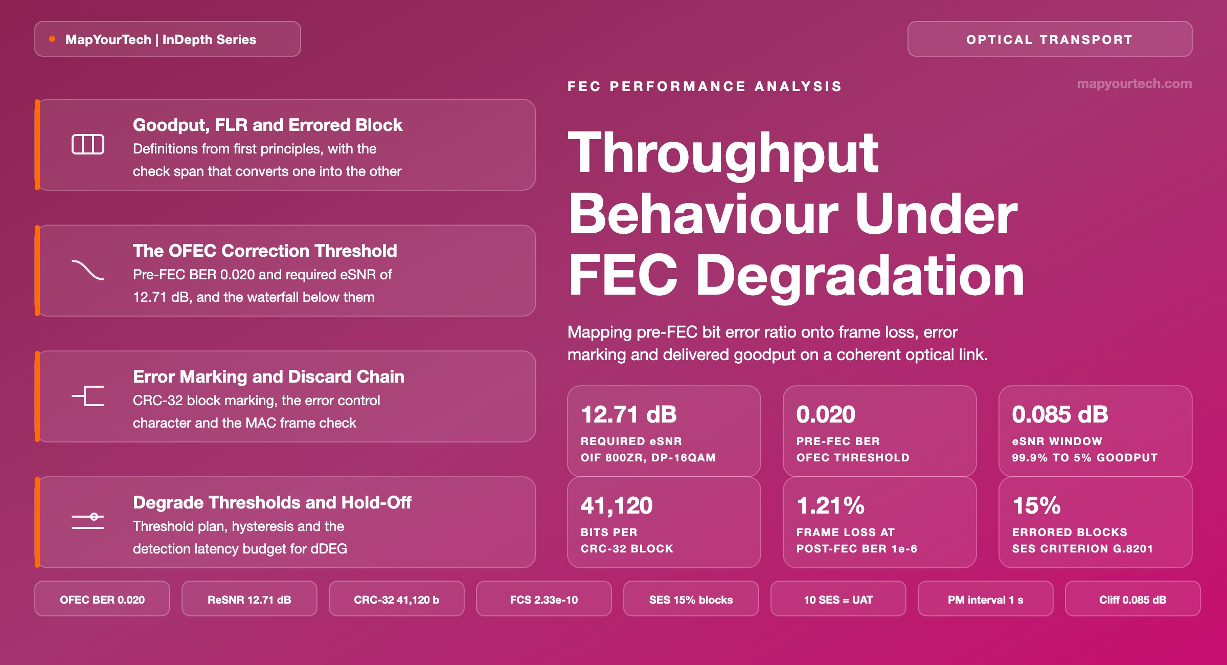
Throughput Behaviour Under FEC Degradation
Mapping pre-FEC bit error ratio onto frame loss, error marking and delivered goodput on a coherent optical link.
FEC holds until it does not, and then it does not gradually.
What You Will Learn
- Define goodput, frame loss ratio and errored block from first principles, and convert between them using FLR = 1 − (1 − p)8L (Section 2, Figure 1).
- Place the Open FEC (OFEC) correction threshold at a pre-FEC BER of 2.0 × 10⁻² and a required effective signal-to-noise ratio (eSNR) of 12.71 dB for dual-polarization 16QAM (Section 3).
- Trace the discard chain from an uncorrected forward error correction (FEC) codeword through cyclic redundancy check (CRC-32) error marking, the error control character and the media access control (MAC) frame check (Section 4, Figure 3).
- Quantify frame loss against post-FEC BER for 64, 1518 and 9000-octet frames from Table 2 and Figure 4.
- Select between the independent-bit and burst-error models, which disagree by a factor of 24 on how frame size scales loss (Section 6, Table 3).
- Read the 0.085 dB effective-SNR window over which goodput falls from 99.9% to 5%, and answer the 95% throughput question with it (Section 7, Figure 5).
- Configure FEC degrade thresholds, hysteresis and the DEGM bad-second count against the detection latency budget in Figure 6 (Section 8).
- Anchor errored-second and unavailability accounting to the 15% errored-block criterion and the ten-second unavailability onset (Section 9).
1. Introduction
An 800GE client riding a single coherent wavelength carries 65.02 million maximum-length frames every second, and every one of them is protected by a 32-bit frame check sequence that either matches or does not. Between the fiber and that check sits a forward error correction (FEC) decoder that corrects completely up to a threshold and then stops correcting. The two facts together decide what an operator sees when a link degrades, and the answer surprises engineers who expect the packet layer to track the physical layer smoothly.
Physical degradation is continuous. Amplifier noise accumulates, connectors age, a splice shifts, polarization state wanders, and the receiver's effective signal-to-noise ratio (eSNR) falls by hundredths of a decibel per week. Pre-FEC bit error ratio (BER) rises smoothly and monotonically with that fall. Nothing about the optical layer is discontinuous. The discontinuity is introduced by the decoder: open FEC (OFEC) holds its output below an error floor of 1 × 10⁻¹⁵ across the whole span of input degradation up to a pre-FEC BER of 2.0 × 10⁻², and then releases errors over an input window a few percent wide (standard-specified, OIF 800ZR Implementation Agreement, clause 7.3.5).
The packet layer then amplifies that discontinuity a second time. A single errored bit anywhere in a 1,518-octet frame fails the frame check sequence (FCS) and the whole frame is discarded, so a post-FEC BER of 1 × 10⁻⁶ costs 1.21% of frames rather than one millionth of the traffic (derived). Two multiplications of the same underlying physical change — one by the decoder, one by the frame length — are why an optical link runs at full rate or close to nothing, and why the statement "the link is running at 95% throughput" describes an average over a measurement window rather than a state the link occupies.
This article covers the full chain: the definitions that make goodput measurable, the FEC threshold and its position in eSNR, the error marking and consequent actions specified for 800ZR interfaces, the frame loss arithmetic under both independent-bit and burst-error statistics, the degrade signalling and defect declaration that convert a physical trend into a management event, and the error performance objectives against which the result is judged. Boundary conditions are stated where a model stops holding. Every figure carries its evidence class in the sentence that states it.
2. Goodput, Frame Loss Ratio and Errored Block Definitions
Goodput is the rate at which client payload octets arrive intact and pass the receiving media access control (MAC) frame check sequence, measured in bits per second. Goodput excludes preamble, inter-packet gap and every frame discarded for a failed check, so it is always lower than the line rate the interface reports. The quantity is defined per direction and per client port.
The check itself is the 32-bit CRC-32 computed over the frame from the destination address through the payload and transmitted in the four-octet FCS field. Figure 1 draws the frame to scale and states what the check protects.
Three other quantities sit close enough to goodput to be confused with it, and separating them is where most of the confusion about degraded links begins.
Read the Full Analysis with Premium
The remaining 88% of this article — the design numbers, trade-offs and field guidance — is part of MapYourTech Premium, along with the full premium library, courses and professional tools.
You May Also Like

-
Free
-
September 4, 2026

-
Premium
-
September 4, 2026

-
Premium
-
September 4, 2026