
Wet Plant vs Dry Plant Equipment
in Submarine Networks
1. Introduction
Submarine fiber optic cable systems form the backbone of global internet connectivity, carrying over 99% of intercontinental data traffic and enabling more than $10 trillion in daily financial transactions. These sophisticated underwater telecommunications networks comprise two fundamentally distinct infrastructure categories: wet plant (submerged equipment) and dry plant (shore-based equipment).
The distinction between wet and dry plant represents a critical architectural separation in submarine cable systems. This division emerged from both practical engineering requirements and operational considerations, as equipment operating on the ocean floor faces vastly different challenges than systems housed in terrestrial facilities. Understanding this separation is essential for network engineers, system designers, and telecommunications professionals working with submarine infrastructure.
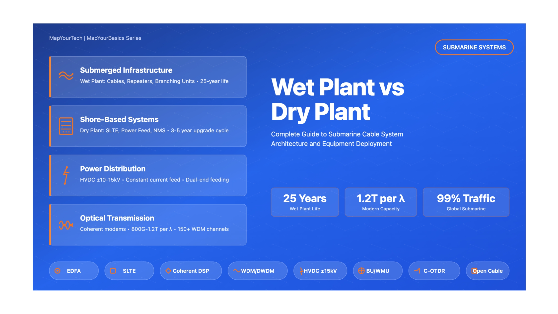
1.1 What is Wet Plant Equipment?
Wet plant refers to all equipment deployed underwater, from the beach manhole at one shore to the beach manhole at the destination shore. This includes the submarine fiber optic cables, optical amplifiers (repeaters), branching units, wavelength management units, and all associated submerged hardware. The term "wet plant" emphasizes that this equipment operates in the harsh marine environment, subjected to extreme pressure, corrosion, and inaccessibility.
Wet plant components are engineered for a design life of 25 years with minimal intervention, as repairs require specialized cable ships and can take weeks to complete. At depths reaching 8,000 meters, the equipment must withstand pressures exceeding 800 bar (80 MPa) while maintaining optical performance and reliability.
1.2 What is Dry Plant Equipment?
Dry plant encompasses all shore-based infrastructure including the Submarine Line Terminating Equipment (SLTE), Power Feed Equipment (PFE), network management systems, and monitoring equipment. This equipment resides in Cable Landing Stations (CLS) located on land, typically within a few kilometers of the shore.
Unlike wet plant, dry plant can be accessed, maintained, and upgraded regularly. SLTE technology typically follows Moore's Law, with capacity upgrades occurring every 3-5 years to leverage advances in digital signal processing, coherent modulation formats, and forward error correction techniques.
1.3 Why This Separation Matters
The wet plant versus dry plant distinction is critical for several reasons:
Technical Considerations
- Different environmental requirements and constraints
- Vastly different maintenance access and repair cycles
- Distinct reliability and redundancy strategies
- Separate power distribution architectures
Operational Impact
- Upgrade cycles: Wet plant lasts 25+ years, dry plant upgrades every 3-5 years
- Cost structure: Wet plant is capital-intensive, dry plant offers flexibility
- Vendor selection: Open cable systems allow multi-vendor SLTE
- Capacity evolution: Dry plant upgrades increase system capacity
Business Model
- Enables "open cable" architectures for vendor independence
- Facilitates capacity-on-demand business models
- Allows fiber pair ownership and spectrum sharing
- Supports progressive investment strategies
2. Historical Context and Evolution
The architectural separation between wet and dry plant has evolved significantly over the past four decades, driven by technological innovations and changing operational requirements.
2.1 The EDFA Revolution (1990s)
The introduction of Erbium-Doped Fiber Amplifiers (EDFAs) in the mid-1990s fundamentally transformed submarine cable architecture. Prior to EDFAs, submarine systems used electronic regenerators that required bit-rate-specific electronics in the submerged equipment. This created tight coupling between wet and dry plant, as any capacity upgrade required replacing or adding underwater repeaters.
EDFAs enabled bit-rate-independent optical amplification, allowing the wet plant to remain fixed while the dry plant (SLTE) could be upgraded to support higher data rates and new modulation formats. This was the genesis of the modern wet-dry plant separation.
2.2 Coherent Modems and Simplified Wet Plant (2010s)
The advent of coherent digital signal processing in submarine systems around 2010-2012 further simplified wet plant design. Coherent modems could compensate for chromatic dispersion electronically, eliminating the need for multiple fiber types and complex dispersion compensation schemes in the wet plant. Modern submarine cables now use a single fiber type (typically low-loss, large effective area fiber), dramatically simplifying wet plant engineering and reducing costs.
2.3 Open Cable Systems (2017-Present)
Since 2017, the submarine cable industry has seen the emergence of "open cable" architectures where wet plant and dry plant are completely disaggregated from day one. In these systems, fiber pair owners can select SLTE from their preferred vendor, enabling competition and innovation. This represents the culmination of the wet-dry plant separation philosophy.
As of 2024-2025, open cable systems dominate new deployments, with major technology providers like Ciena, Infinera, Nokia (ASN), and NEC competing in the SLTE market while wet plant specialists focus on high-reliability underwater infrastructure.
3. Core Concepts and Fundamentals
3.1 Wet Plant Components in Detail
The wet plant comprises several critical components, each engineered for extreme reliability in the underwater environment:
Critical Wet Plant Design Requirements
Pressure Resistance: Equipment must withstand up to 800 bar (80 MPa) at 8000m depth without structural failure or performance degradation. This requires specialized pressure housing designs with beryllium copper or titanium alloys.
Hermetic Sealing: Absolute water-tightness is essential. Even microscopic water ingress can lead to catastrophic failure. Modern designs use laser-welded seams and glass-to-metal seals for optical and electrical feedthroughs.
Thermal Management: With no active cooling, wet plant must dissipate heat through natural convection to seawater. Operating temperatures range from -2°C in deep polar waters to +25°C in shallow tropical regions.
| Wet Plant Component | Function | Typical Specifications | Reliability Target |
|---|---|---|---|
| Optical Repeater | Amplifies optical signals using EDFA technology | Gain: 15-20 dB Spacing: 70-100 km Power: 0.5-1.5W per fiber pair |
< 2-3 failures per system over 25 years |
| Branching Unit (BU) | Routes fiber pairs between trunk and branch cables | 2-4 cable ports Power switching Telemetry capability |
< 1 failure per 25 years |
| Wavelength Mgmt Unit (WMU) | Optical add/drop and wavelength routing | ROADM capable 40-150 channel capacity Remote reconfigurable |
< 1 failure per 25 years |
| Submarine Cable | Transmits optical signals and electrical power | 2-24 fiber pairs 10-15 kV DC power Armored for protection |
< 0.1 faults per 1000 km-year (deep water) |
3.2 Dry Plant Components in Detail
The dry plant encompasses shore-based equipment that can be accessed, maintained, and regularly upgraded:
| Dry Plant Component | Primary Function | Key Specifications | Upgrade Cycle |
|---|---|---|---|
| SLTE - Transponders | Coherent modulation/demodulation, FEC, DSP | 800G-1.2T per wavelength 16-QAM modulation Soft-decision FEC |
3-5 years (technology-driven) |
| SLTE - WDM System | Wavelength multiplexing and demultiplexing | 150+ channels 33-37.5 GHz spacing C+L band capability |
10-15 years |
| Power Feed Equipment | HVDC power supply to wet plant | ±10-15 kV DC 1-2 A current Dual-end or single-end feed |
15-25 years (static component) |
| Network Management | System monitoring, control, provisioning | SNMP/NETCONF Performance monitoring Fault management |
Continuous software updates |
Open Cable Interface Standards
In open cable systems, the interface between wet plant and dry plant is standardized to enable multi-vendor SLTE deployment. Key parameters that must be exchanged include:
- Power Budget Table (PBT): Detailed span-by-span loss characteristics
- Straight Line Diagram (SLD): Complete system topology and component locations
- Fiber Characterization: Dispersion, PMD, effective area for each span
- Repeater Parameters: Gain, noise figure, saturation characteristics
- OSNR Requirements: Target optical signal-to-noise ratios at receivers
4. Technical Architecture & System Design
4.1 End-to-End System Architecture
A complete submarine cable system integrates wet and dry plant components into a cohesive network architecture. The following diagram illustrates a typical transoceanic trunk-and-branch system configuration:
4.2 Power Distribution Architecture
One of the most critical aspects of submarine cable design is the power feeding architecture. All wet plant equipment (repeaters, branching units) requires electrical power, which must be delivered through the submarine cable itself over distances exceeding 10,000 km.
The power feeding system operates on constant current control, typically 0.8-1.5 amperes DC. The power feed equipment at each shore station applies high voltage (±10 to ±15 kV DC), with the voltage dropping across each repeater. The current returns through seawater and the earth, completing the circuit via sea ground electrodes.
This architecture allows repeaters to be series-connected, with each consuming a small portion of the total system power budget. A typical transoceanic system with 150 repeaters might operate at ±12 kV and 1.0 A, providing 24 kW total power budget distributed across all wet plant equipment.
5. Mathematical Models and System Calculations
5.1 OSNR Budget Calculation
Optical Signal-to-Noise Ratio (OSNR) is the critical performance metric in submarine systems. The end-to-end OSNR determines the maximum achievable data rate and system reach. For a multi-span system with optical amplifiers, the OSNR can be calculated as:
The fundamental OSNR equation for a multi-span amplified system is:
OSNR Calculation Details
Individual Span OSNR: OSNRspan = Pout / (2·h·ν·(G-1)·NF·Bref)
Multi-Span System: For N identical spans, the total noise adds linearly in power, so:
1/OSNRtotal = Σ(1/OSNRi) for i=1 to N
Typical Values:
- Target OSNR at receiver: 18-22 dB (depends on modulation format)
- EDFA Noise Figure (NF): 4.5-6 dB
- Reference bandwidth Bref: 12.5 GHz (0.1 nm)
- Planck constant h = 6.626×10⁻³⁴ J·s
- Optical frequency ν ≈ 193 THz (C-band)
5.2 Power Budget and Link Design
The power budget determines the maximum transmission distance and repeater spacing. For submarine systems, the link power budget must account for:
| Parameter | Typical Value | Impact on Design |
|---|---|---|
| Fiber Attenuation | 0.17-0.20 dB/km @ 1550nm | Determines repeater spacing (70-100 km typical) |
| Splice Loss | 0.05-0.1 dB per splice | Adds to span loss, ~1-2 dB total per span |
| EDFA Gain | 15-22 dB | Must match span loss + margins |
| Nonlinear Penalty | 1-3 dB | Limits launch power, increases OSNR requirement |
| System Margin | 3-6 dB | Accounts for aging, repairs, temperature variations |
The repeater spacing is determined by:
Lspan = (Pout - Pin,min - Margins) / α
Where α is fiber attenuation (dB/km), Pout is amplifier output power, and Pin,min is minimum input power to next amplifier.
6. Types and System Configurations
6.1 Wet Plant Configurations
Point-to-Point Systems
Configuration: Simple two-terminal system
- Single cable route between two shores
- No branching units required
- Lowest complexity and cost
- Example: Short regional cables
Trunk-and-Branch Networks
Configuration: Main trunk with lateral branches
- Branching units route traffic to multiple shores
- Complex power feeding arrangements
- Wavelength management units for add/drop
- Example: Transoceanic systems serving multiple countries
Mesh Networks
Configuration: Multiple interconnected cables
- High redundancy and resilience
- Multiple path diversity
- Complex route management
- Example: Regional cable systems in SE Asia
6.2 Dry Plant System Types
Open Cable Market Drivers (2024-2025)
The submarine cable industry has fully embraced open cable architectures driven by:
- Hyperscale Content Providers: Google, Meta, Amazon, Microsoft now own/co-own 70%+ of new submarine cables and demand multi-vendor flexibility
- SLTE Innovation: Rapid advances in coherent modems (800G to 1.2T per wavelength) benefit from competitive market
- Cost Optimization: Open systems enable capacity-on-demand and progressive investment strategies
- Standards Evolution: ITU-T G.977.1 provides framework for open cable specifications
- Vendor Ecosystem: Ciena, Infinera, Nokia/ASN, NEC compete in SLTE while specialized vendors focus on wet plant
7. Advanced Visual Demonstrations
7.1 Signal Flow and Data Path Visualization
7.2 Power Feeding and Protection Switching
8. Practical Applications and Real-World Considerations
8.1 System Design Example: Trans-Pacific Cable
Consider a practical example of a modern transpacific submarine cable system connecting Los Angeles to Tokyo (approximately 9,000 km):
| System Parameter | Wet Plant Specification | Dry Plant Specification |
|---|---|---|
| Total Distance | ~9,000 km undersea route | CLS to POP: 20-50 km terrestrial backhaul |
| Fiber Pairs | 6-12 fiber pairs in cable | Each pair terminated in separate SLTE |
| Repeater Count | ~110-130 repeaters @ 70-80 km spacing | N/A (no repeaters in dry plant) |
| Power Feed | Dual-end feed: ±14 kV, 1.2 A Total: ~34 kW system power |
Two PFE stations (LA and Tokyo) Each: 20-25 kW capacity |
| Capacity per Fiber Pair | Fixed by EDFA bandwidth: C+L band Supports 150+ wavelength channels |
Initial: 12-18 Tb/s (2024 SLTE) Future: 24-30 Tb/s (with upgrades) |
| Design Life | 25 years minimum Component failure rate: <2-3 per system life |
SLTE: 3-5 year upgrade cycle PFE: 15-25 years |
| Investment | ~$250-350M (cable, repeaters, installation) | ~$50-100M (SLTE, PFE, CLS facilities) |
8.2 Maintenance and Repair Considerations
The operational distinction between wet and dry plant becomes most apparent during maintenance and fault scenarios:
Dry Plant Maintenance
- Accessibility: Equipment in climate-controlled facilities
- Hot-swappable components: Redundant power, transponders
- Software upgrades: Remote provisioning and updates
- Preventive maintenance: Regular inspection schedules
- Repair time: Hours to days
- Spare strategy: Local spares for critical components
Wet Plant Maintenance
- Accessibility: Requires specialized cable ship
- No hot-swap: Complete unit replacement only
- No remote updates: Firmware fixed at deployment
- Preventive maintenance: Not possible underwater
- Repair time: Weeks to months
- Spare strategy: Pre-positioned repeaters, BUs on cable ship
Cable Fault Repair Process
When a submarine cable fault occurs:
- Fault Detection (Minutes): Automated monitoring systems detect loss of signal or power anomalies
- Fault Localization (Hours): C-OTDR and power measurements pinpoint fault location (±1 km accuracy)
- Cable Ship Mobilization (Days): Nearest cable ship dispatched to fault site with spare equipment
- Recovery Operation (Days): Cable grappled from seabed, brought to surface (1-3 days depending on depth)
- Repair and Splicing (Hours): Faulty section cut out, new cable/repeater spliced in
- Redeployment and Testing (Days): Cable re-laid, system tested and restored to service
Total time: Typically 2-6 weeks depending on location, weather, and cable ship availability
8.3 Future Trends and Innovations
Emerging Technologies (2024-2030)
Wet Plant Innovations:
- Space Division Multiplexing (SDM): Multi-core and multi-mode fibers to increase capacity beyond single-fiber Shannon limits
- Wider Bandwidth Amplifiers: S+C+L band EDFAs enabling 200+ wavelength channels
- Remote Raman Amplification: Distributed amplification to extend repeater spacing to 150+ km
- Intelligent Repeaters: Adaptive gain equalization and spectral monitoring capabilities
Dry Plant Innovations:
- 1.2T+ Coherent Modems: Next-generation DSP enabling 1.2-1.6T per wavelength
- Probabilistic Constellation Shaping: Adaptive modulation optimizing SNR utilization
- AI/ML Network Optimization: Automated capacity planning, fault prediction, and performance optimization
- Open Line System APIs: Standardized interfaces enabling true multi-vendor interoperability
Key Takeaways
1. Fundamental Separation: Wet plant (submerged) and dry plant (shore-based) represent architecturally distinct infrastructure with vastly different operational characteristics.
2. Wet Plant Longevity: Submarine cables and repeaters are designed for 25+ year lifespan with near-zero maintenance, requiring extreme reliability engineering.
3. Dry Plant Flexibility: SLTE technology evolves every 3-5 years, enabling capacity upgrades without wet plant modifications.
4. Open Cable Revolution: Since 2017, open cable systems enable multi-vendor SLTE deployment, breaking historical vendor lock-in.
5. Power Architecture: HVDC constant-current feeding (±10-15 kV, 1-2 A) powers all wet plant through series-connected repeaters.
6. OSNR Management: Amplified spontaneous emission (ASE) noise accumulates with each repeater, requiring careful power budget design to maintain adequate OSNR.
7. Coherent Technology Impact: Digital signal processing in dry plant compensates for chromatic dispersion, simplifying wet plant to single fiber type.
8. Capacity Evolution: Modern systems achieve 800G-1.2T per wavelength with 150+ channels, delivering 30+ Tb/s per fiber pair.
9. Fault Recovery: Wet plant faults require specialized cable ships and weeks to repair, while dry plant issues resolve in hours to days.
10. Future Direction: Space division multiplexing (SDM) in wet plant combined with AI-optimized dry plant will drive next-generation capacity growth.
For educational purposes in optical networking and DWDM systems
Note: This guide is based on industry standards, best practices, and real-world implementation experiences. Specific implementations may vary based on equipment vendors, network topology, and regulatory requirements. Always consult with qualified network engineers and follow vendor documentation for actual deployments.

Optical Communications & Network Automation Expert | Author of 3 Books for Optical Engineers | Founder, MapYourTech
Optical networking engineer with nearly two decades of experience across DWDM, OTN, coherent optics, submarine systems, and cloud infrastructure. Founder of MapYourTech. Read full bio →
Follow on LinkedInRelated Articles on MapYourTech


Continue Reading This Article
Sign in with a free account to unlock the full article and access the complete MapYourTech knowledge base.