
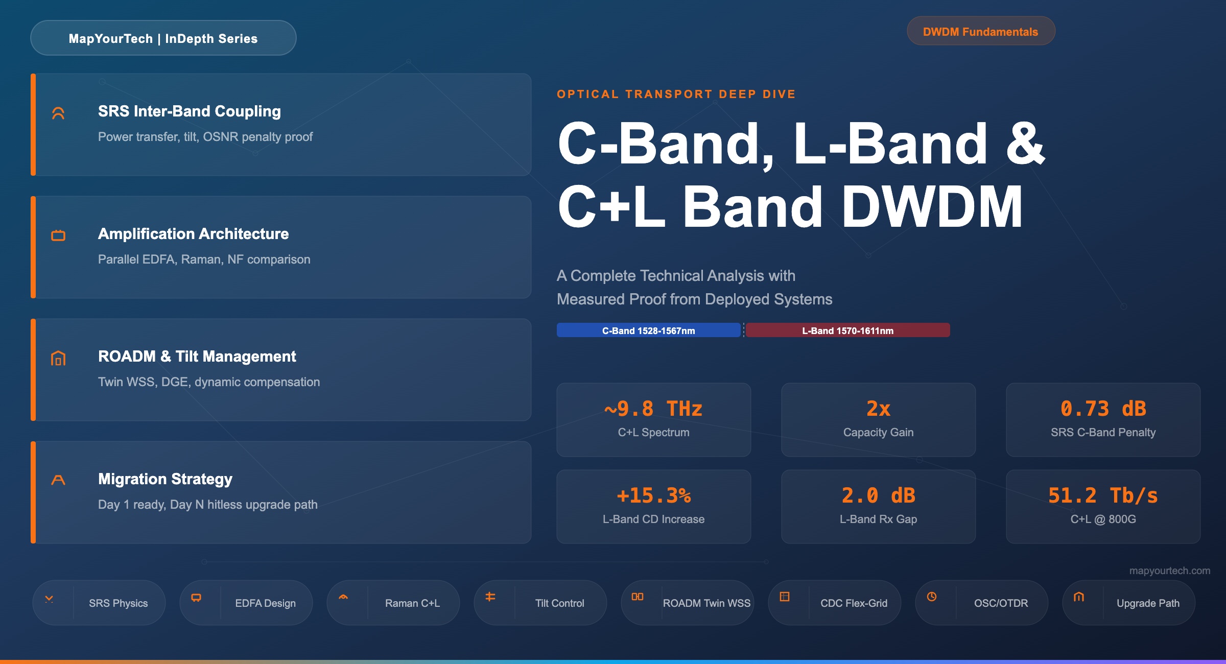
C-Band, L-Band, and C+L Band DWDM: A Complete Technical Analysis
Spectral characteristics, inter-band coupling, amplification architecture, tilt management, ROADM design implications, and migration strategies for optical transport networks
1. Introduction
The demand for fiber capacity continues to grow at 25–30% annually, driven by cloud interconnect, 5G transport, and content delivery. For operators who have exhausted their C-band capacity, the L-band offers the most accessible spectrum expansion — doubling the usable bandwidth on existing fiber plant without deploying new cables. However, adding L-band to an operational C-band network introduces a set of physical layer interactions that change the engineering rules for every component in the optical line system.
This article provides a detailed technical analysis of C-band-only, L-band-only, and integrated C+L band DWDM systems. It covers the underlying physics of each band, the inter-band effects that arise when both bands share a fiber, the amplification and ROADM architecture changes required, and the practical engineering trade-offs involved in upgrading from C-band to C+L. Every parameter discussed — wavelength ranges, attenuation coefficients, dispersion values, amplifier noise figures, and SRS penalties — is grounded in deployed system specifications and ITU-T standards.
2. Spectral Band Fundamentals
2.1 ITU-T Band Definitions and Wavelength Ranges
The International Telecommunication Union defines several spectral bands for optical fiber communications. For DWDM transport, two bands dominate deployed infrastructure:
C-band (Conventional band): 1528.77 nm to 1568.36 nm (191.35 THz to 196.10 THz). This is the primary DWDM transport window, aligned with the lowest-loss region of silica fiber and the gain peak of erbium-doped fiber amplifiers (EDFAs). Extended C-band implementations push the boundaries slightly to 1528–1567 nm, adding approximately 0.6 THz of additional usable spectrum.
L-band (Long-wavelength band): 1568.77 nm to 1610.06 nm (186.10 THz to 191.10 THz). The L-band sits immediately adjacent to the C-band on the longer-wavelength side. It uses the same silica fiber but requires separate amplification, different transceiver designs, and introduces inter-band coupling effects when co-propagated with C-band signals.
2.2 Channel Plans and Grid Spacing
Under ITU-T G.694.1, both C and L bands support flexible grid operation with 6.25 GHz granularity. In practice, deployed channel plans use 50 GHz, 75 GHz, 100 GHz, or 150 GHz spacing depending on the line rate and modulation format. At 800G with ~131 Gbaud symbol rate and DP-QPSK/PCS modulation, a 150 GHz channel slot is typical, yielding approximately 32 channels per band or 64 channels in C+L. Higher-performance transceivers operating at 800G with 98 Gbaud and PCS-16QAM can pack into 112.5 GHz slots, yielding up to 42 channels per C-band alone.
The frequency grid is defined from an anchor frequency of 193.1 THz (1552.52 nm) with slots at 193.1 + n × 0.00625 THz, where n is a positive or negative integer. For flex-grid operation, each channel occupies m × 12.5 GHz of spectrum, where m is chosen to accommodate the signal bandwidth plus guard bands.
3. Fiber Physical Layer: C-Band vs L-Band
3.1 Attenuation Profile
Standard single-mode fiber (ITU-T G.652D) exhibits its minimum attenuation near 1550 nm, at approximately 0.19–0.20 dB/km. The attenuation across the C and L bands varies slightly but with an interesting characteristic: the L-band attenuation on modern low-water-peak G.652D fiber is approximately 0.20–0.22 dB/km, only marginally higher than the C-band minimum. Over a typical 100 km span, this translates to approximately 0.5–1.0 dB of additional loss in the L-band compared to the C-band center.
This near-parity in attenuation is what makes L-band attractive. Unlike the O-band (1260–1360 nm) where attenuation rises to 0.33–0.35 dB/km, or the S-band (1460–1530 nm) which suffers from water peak absorption in legacy fibers, the L-band provides a large, clean spectrum window with attenuation very close to the C-band optimum.
Practical impact: On a 100 km span of G.652D fiber, the typical total loss is approximately 20 dB at C-band center (1550 nm) and approximately 21 dB at L-band center (1590 nm). Including connectors, splices, and aging margin, an end-of-life (EOL) budget of 23 dB is commonly used for both bands on a 100 km span.
3.2 Chromatic Dispersion
Chromatic dispersion (CD) is the primary linear impairment in long-haul optical transmission. On G.652D fiber, the dispersion coefficient D increases monotonically with wavelength across both the C and L bands:
Read the Full Analysis with Premium
The remaining 89% of this article — the design numbers, trade-offs and field guidance — is part of MapYourTech Premium, along with the full premium library, courses and professional tools.
You May Also Like
-
Premium
-
September 1, 2026
-
Premium
-
September 1, 2026
-
Free
-
August 31, 2026