
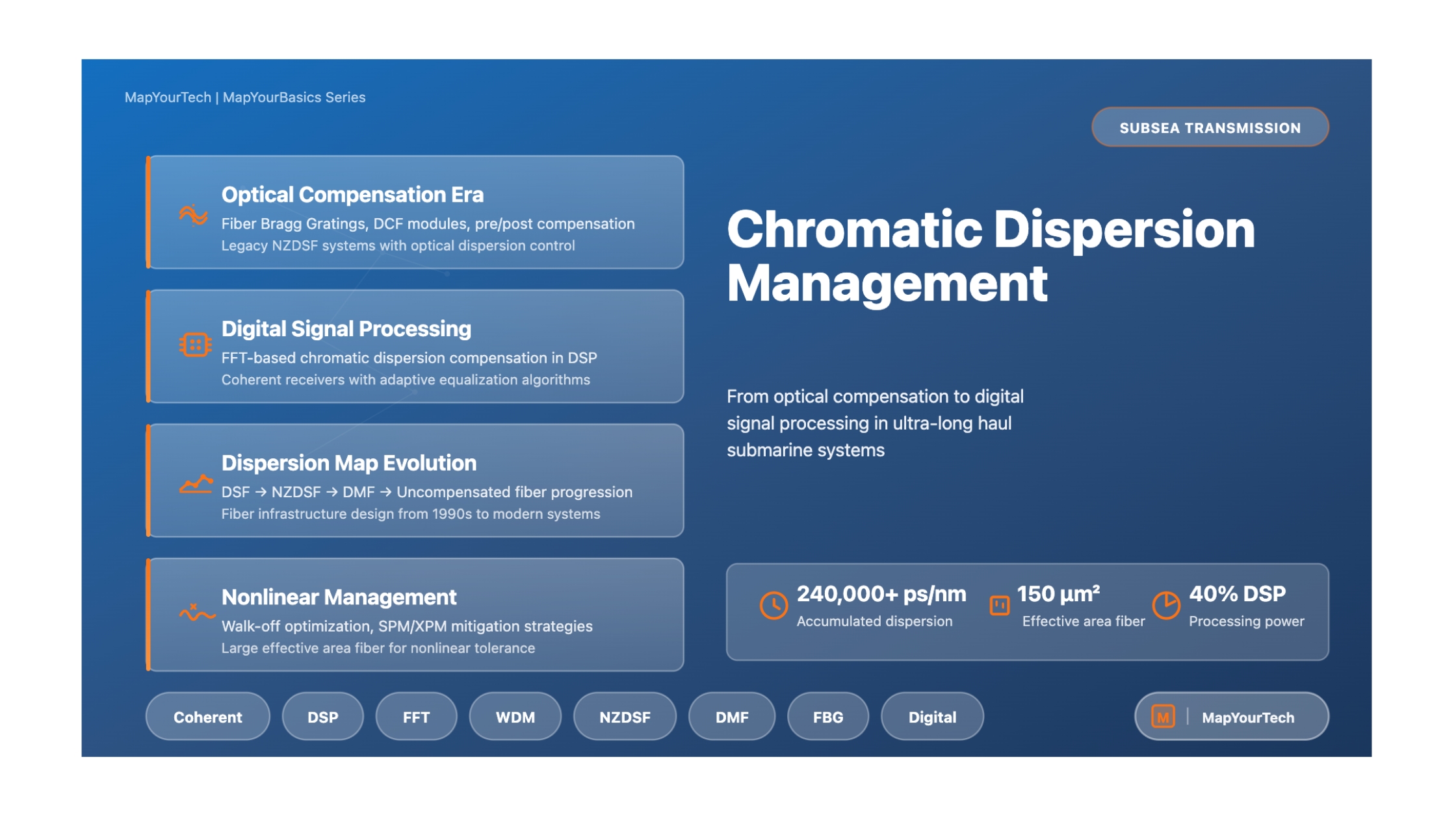
Chromatic Dispersion Management in Subsea Systems
From Optical Compensation to Digital Signal Processing in Ultra-Long Haul Transmission
Introduction
Chromatic dispersion represents one of the most fundamental transmission impairments in optical fiber submarine systems. As optical signals propagate through fiber over transoceanic distances, different wavelength components travel at different velocities, causing pulse broadening and signal degradation. In subsea systems spanning thousands of kilometers, accumulated chromatic dispersion can reach hundreds of thousands of picoseconds per nanometer, presenting significant engineering challenges for system designers.
The management of chromatic dispersion has evolved dramatically over the past three decades, transitioning from purely optical compensation techniques to sophisticated digital signal processing methods. This evolution has been driven by the relentless demand for increased transmission capacity and longer reach in submarine cable systems connecting continents and enabling global communications infrastructure. This article examines the technical principles, architectural approaches, and practical considerations that define modern chromatic dispersion management in subsea transmission systems.
Modern submarine systems employing coherent detection and digital compensation can tolerate accumulated dispersion exceeding 240,000 ps/nm over 12,000 km transmission links, a feat that would have been impossible with earlier optical compensation techniques alone. Understanding the principles, architectures, and practical considerations of chromatic dispersion management is essential for engineers working on subsea transmission systems, whether designing new installations or planning capacity upgrades for existing infrastructure.
Fundamental Principles
Physical Origin of Chromatic Dispersion
Chromatic dispersion arises from the wavelength-dependent refractive index of silica optical fiber. The dispersion parameter D, measured in ps/(nm·km), quantifies how much pulse spreading occurs per unit wavelength deviation per unit length. For standard single-mode fiber operating at 1550 nm, the dispersion is approximately 17 ps/(nm·km), while modern subsea fibers designed for coherent systems typically exhibit values around 20-21 ps/(nm·km).
The dispersion slope, denoted as S and measured in ps/(nm²·km), describes how the dispersion parameter varies with wavelength. This becomes critically important in wavelength division multiplexed systems where different channels experience different amounts of accumulated dispersion. The ratio of dispersion to dispersion slope, κ = D/S, is a key parameter in designing dispersion-managed systems where both chromatic dispersion and dispersion slope must be compensated simultaneously.
Accumulated Dispersion:
D_total = D × L
where D is the dispersion parameter (ps/(nm·km)) and L is the transmission distance (km)
Example: For a 9,000 km transpacific link with D = 21 ps/(nm·km):
D_total = 21 × 9,000 = 189,000 ps/nm
Impact on System Performance
Uncompensated chromatic dispersion causes intersymbol interference as adjacent symbols overlap in time. For intensity-modulated direct-detection systems operating at 10 Gbit/s, even moderate amounts of dispersion can render the signal unrecoverable. The tolerance to chromatic dispersion decreases with the square of the bit rate, making dispersion management increasingly critical as transmission speeds increase to 40 Gbit/s, 100 Gbit/s, and beyond.
Beyond pulse broadening, chromatic dispersion interacts with fiber nonlinearity to produce complex signal distortions. The interplay between dispersion and self-phase modulation, cross-phase modulation, and four-wave mixing fundamentally limits the capacity-distance product of submarine systems. Proper dispersion management is therefore essential not only for compensating linear impairments but also for optimizing the nonlinear transmission regime to maximize system performance.
Technical Architecture and System Design
Evolution of Fiber Infrastructure
The architecture of submarine fiber plants has undergone several major transitions, each driven by advances in transmission technology and dispersion management capabilities. Understanding this evolution provides context for the design choices in modern systems and the challenges faced when upgrading legacy infrastructure.
| Fiber Type | Dispersion @ 1550nm | Effective Area | Primary Era | Compensation Method |
|---|---|---|---|---|
| DSF | ≈ 0 ps/(nm·km) | 50 µm² | 1990s | None (zero dispersion design) |
| NZDSF | 2-4 ps/(nm·km) | 70-75 µm² | 2000s | Periodic DCF modules |
| DMF (+D/-D) | 18-20 / -38 ps/(nm·km) | 100 / 28 µm² | 2010s | Hybrid span design |
| Large Aeff | > 20 ps/(nm·km) | 110-150 µm² | 2015+ | Digital (DSP-based) |
Dispersion Shifted Fiber Systems
The first generation of optically amplified submarine systems deployed dispersion shifted fiber with near-zero chromatic dispersion around 1550 nm. This approach minimized pulse broadening for single-channel transmission at 2.5 or 5 Gbit/s. However, the zero dispersion characteristic proved problematic for wavelength division multiplexing due to efficient four-wave mixing, where photons from different channels interact to generate new frequencies that cause crosstalk and signal degradation.
Non-Zero Dispersion Shifted Fiber Architecture
To enable WDM transmission, non-zero dispersion shifted fiber was introduced with small but non-zero dispersion values of 2-4 ps/(nm·km). This provided sufficient phase mismatch between channels to suppress four-wave mixing while keeping accumulated dispersion manageable. Periodic insertion of dispersion compensating fiber with large negative dispersion allowed for compensation of accumulated dispersion every several spans.
For transpacific systems exceeding 9,000 km, the chromatic dispersion excursion across the WDM multiplex could approach 20,000 ps/nm, requiring per-channel or per-group dispersion precompensation at the transmitter and postcompensation at the receiver. This complexity motivated the development of improved dispersion management approaches.
Dispersion Managed Fiber Design
Dispersion managed fiber architectures combined positive and negative dispersion fibers within each span to simultaneously manage both chromatic dispersion and dispersion slope. A typical configuration consisted of large effective area fiber with positive dispersion (spliced to the repeater output) followed by dispersion compensating fiber with negative dispersion and typically smaller effective area (spliced to the repeater input).
This arrangement provided two key benefits. First, it ensured that high signal power existed primarily in the large effective area section, reducing nonlinear distortions. Second, by matching the ratio of dispersion to dispersion slope in both fiber types, the system achieved flat accumulated dispersion across the entire amplifier bandwidth, eliminating the need for per-channel compensation.
Dispersion Managed Span Design Principle
In hybrid spans, the positive and negative dispersion fibers are designed such that:
D₊ · L₊ + D₋ · L₋ = D_avg · (L₊ + L₋)
where D_avg is the target average span dispersion (typically 2-4 ps/(nm·km)). The dispersion slope matching condition requires:
κ₊ = D₊/S₊ = D₋/S₋ = κ₋
This ensures all wavelengths experience the same accumulated dispersion at the end of each block of spans, enabling broadband WDM operation without per-channel compensation.
Uncompensated Fiber for Coherent Systems
The advent of coherent detection with digital signal processing fundamentally changed dispersion management requirements. Modern systems employ single-fiber-type designs using pure silica core or low-loss fibers with large effective areas (110-150 µm²) and dispersion values exceeding 20 ps/(nm·km). The large effective area minimizes nonlinear distortions, while the high dispersion value promotes interchannel walk-off that further reduces cross-phase modulation.
These uncompensated systems accumulate enormous amounts of dispersion, with 12,000 km transpacific systems experiencing up to 240,000 ps/nm. However, coherent receivers can completely compensate this accumulated dispersion electronically, eliminating the need for complex optical dispersion maps and enabling simplified wet plant designs that facilitate future capacity upgrades.
Operational Behavior and Mechanism
Optical Domain Compensation Techniques
In pre-coherent systems, chromatic dispersion compensation occurred entirely in the optical domain using passive devices or specially designed fibers. The primary technique involved fiber Bragg gratings with chirped patterns that provided wavelength-dependent delay to counteract dispersion accumulation.
Commercially available dispersion compensating modules based on fiber Bragg gratings could compensate up to 10,000 ps/nm over bandwidths of several nanometers with insertion losses around 3-4 dB. However, transpacific systems requiring 200,000 ps/nm or more of compensation would need 20 or more concatenated modules, resulting in prohibitive loss and cost.
An alternative approach used sections of dispersion compensating fiber with large negative dispersion (typically -38 to -90 ps/(nm·km)) and relatively small effective area (28-34 µm²). While effective, DCF introduced additional loss and reduced the overall system effective area, somewhat compromising the nonlinear performance advantage of large effective area transmission fibers.
Digital Coherent Compensation
Modern coherent transceivers perform chromatic dispersion compensation entirely in the digital domain by solving the linear propagation equation backwards. After coherent detection and analog-to-digital conversion, the received optical field is processed through a digital chromatic dispersion compensator that implements the inverse transfer function of the fiber.
The digital compensation process consists of three main steps. First, the time-domain waveform is converted to the frequency domain using a Fast Fourier Transform. Second, the frequency-domain representation is multiplied by the chromatic dispersion transfer function, which applies the inverse of the fiber's dispersive effect. Third, an Inverse Fast Fourier Transform converts the compensated signal back to the time domain.
Chromatic Dispersion Transfer Function:
H_CD(β₂, ω, L) = exp(-iβ₂ω²L/2)
where:
β₂ = dispersion parameter (related to D)
ω = angular frequency offset from carrier
L = transmission distance
The negative sign compensates for the positive dispersion accumulated in the fiber.
FFT Block Size and Processing Requirements
The required FFT size is determined by the total accumulated dispersion and the channel bandwidth. For a transpacific system with 12,000 km distance, dispersion of 21 ps/(nm·km), and 30 GHz (0.24 nm) channel bandwidth, the accumulated dispersion is 240,000 ps/nm, resulting in approximately 1,500 symbols mixed through chromatic dispersion. This requires FFT blocks of similar size with additional overhead for block overlapping.
In practical implementations, chromatic dispersion compensation can consume up to 40% of the total DSP processing power. Modern CMOS processors fabricated at 40 nm, 28 nm, or smaller process nodes provide sufficient computational capability to perform these operations at tens of Gbaud signal rates while maintaining acceptable power consumption levels.
Adaptive Dispersion Estimation
While accumulated dispersion is primarily static, it exhibits small variations over time due to temperature changes, cable stress, and other environmental factors. During transceiver startup, the exact accumulated dispersion value is unknown and must be estimated through a best-match search process that evaluates signal quality across different dispersion compensation values.
Once the optimal dispersion value is determined, the chromatic dispersion compensator operates with that setting. Residual slow variations are tracked and compensated by the adaptive equalizer that follows the dispersion compensation block, which primarily addresses polarization mode dispersion but can also absorb small chromatic dispersion fluctuations.
Performance Considerations and Trade-offs
Dispersion Slope Compensation in Legacy Systems
One of the most significant challenges in optical dispersion management involves compensating both chromatic dispersion and dispersion slope across the full amplifier bandwidth. In NZDSF systems with positive dispersion fibers and periodic DCF insertion, perfect compensation is only achieved at the center wavelength. Channels at longer wavelengths experience positive residual dispersion, while shorter wavelength channels see negative residual dispersion.
Over transpacific distances, this dispersion excursion across a 30+ nm WDM multiplex can exceed 20,000 ps/nm, causing severe signal degradation for outer channels. The solution requires per-channel or per-group precompensation and postcompensation at the terminal equipment, significantly increasing system complexity and cost.
Interchannel Nonlinear Effects in Tight Dispersion Maps
Maintaining low accumulated dispersion throughout the transmission path creates conditions favorable for interchannel nonlinear effects, particularly cross-phase modulation and four-wave mixing. When dispersion is tightly controlled, symbols from different wavelength channels travel at similar speeds, resulting in extended nonlinear interaction lengths.
This pattern-dependent interaction can severely distort phase-modulated signals. The phenomenon is particularly pronounced in dispersion-managed fiber systems where dispersion is compensated within each span. While these maps achieve excellent dispersion control, they suffer from reduced interchannel walk-off, making them less suitable for high-order modulation formats at close channel spacings.
Walk-off and Nonlinear Mitigation
Interchannel walk-off refers to the relative velocity difference between symbols at different wavelengths caused by chromatic dispersion. Large walk-off provides an averaging effect where each symbol interacts with many symbols from other channels, resulting in common phase noise that is relatively harmless.
When walk-off is small (tight dispersion management), symbols from different channels travel together for extended distances, producing pattern-dependent phase noise that is difficult to compensate. This represents a fundamental trade-off between dispersion control and nonlinear tolerance in pre-coherent systems.
Equalization Enhanced Phase Noise
Digital chromatic dispersion compensation introduces a subtle penalty known as equalization enhanced phase noise. This phenomenon arises because the phase noise contribution from the local oscillator laser in the coherent receiver is enhanced when the all-pass fiber transfer function is applied during dispersion compensation.
Mathematically, this effect occurs due to the non-commutativity of convolution and multiplication operators. In submarine systems with very large accumulated dispersion, EEPN can become significant. However, modern lasers with linewidth below 100 kHz maintain EEPN penalties within acceptable limits even after 10,000 km transmission with full digital dispersion compensation.
Dispersion Map Uncertainty and Variability
The actual dispersion map of an installed submarine system differs from the design target due to numerous sources of uncertainty. These include measurement uncertainties in fiber zero-dispersion wavelength, dispersion parameter, and dispersion slope, as well as temperature and pressure coefficient variations in the installed cable.
Additional factors such as random selection of fiber sections during cable assembly, aging effects, and repair operations contribute to dispersion map variations. System design must account for these uncertainties through margin allocation and, in optical compensation systems, through adjustable dispersion compensation devices at the terminals.
Effective Area Trade-offs in Hybrid Spans
Dispersion managed fiber designs combining positive and negative dispersion fibers face an inherent trade-off related to effective area. Dispersion compensating fiber typically exhibits smaller effective area (28-34 µm²) compared to large effective area transmission fiber (100-150 µm²). The overall system performance is determined by an equivalent effective area that accounts for power distribution between the two fiber types.
While the positive dispersion fiber may offer excellent nonlinear performance due to large effective area, the presence of DCF with smaller effective area reduces the overall system equivalent effective area. Careful span design is required to maximize the length of large effective area fiber while providing adequate dispersion compensation, typically targeting a positive-to-negative fiber length ratio of 2:1 to 3:1.
Practical Applications and Use Cases
Terminal Equipment Configuration
In systems employing optical dispersion compensation, the terminal equipment must include adjustable dispersion compensating devices to handle per-channel or per-wavelength-group requirements. These may consist of tunable dispersion compensators, fixed DCF modules with patch panel configurations, or fiber Bragg grating based devices with appropriate bandwidth coverage.
The required compensation range is determined by the worst-case dispersion excursion across the WDM multiplex plus system uncertainties. For a transpacific NZDSF system, edge channels may require up to ±10,000 ps/nm of precompensation and similar amounts of postcompensation, necessitating substantial terminal equipment facilities.
Open Cable Systems and Wet Plant Design
The transition to uncompensated fiber designs with digital dispersion compensation has enabled the development of open submarine cable systems where the wet plant (submarine infrastructure) is independent of the specific transmission technology. This allows system owners to source coherent modems from multiple vendors and perform capacity upgrades without concern for detailed dispersion map compatibility.
This architectural simplification has significantly impacted the submarine cable industry, reducing deployment costs and increasing flexibility for future technology insertions. The wet plant can be designed for optimal optical performance using single-fiber-type configurations with maximized effective area and minimized loss, while all transmission impairment compensation is handled electronically in the terminals.
Performance Optimization Strategies
In modern uncompensated systems, the combination of large accumulated dispersion and large effective area fiber provides important benefits for nonlinear performance. The high dispersion value promotes symbol spreading in time, reducing peak power and mitigating self-phase modulation. Additionally, large interchannel walk-off reduces cross-phase modulation through the averaging mechanism described earlier.
Four-wave mixing is almost completely suppressed due to the large phase mismatch between WDM channels in the high-dispersion regime. The result is a transmission environment where fiber nonlinearity, while still the ultimate capacity limitation, is significantly reduced compared to dispersion-managed systems with the same fiber effective area.
System Upgrade Considerations
Legacy submarine cables with dispersion-managed fiber configurations present unique challenges for capacity upgrades using modern coherent technology. While digital signal processing can compensate the accumulated dispersion, the fiber characteristics may not be optimal for coherent transmission. In particular, DMF systems with periodic DCF sections have reduced equivalent effective area that limits nonlinear performance.
Despite these limitations, significant capacity increases are achievable through coherent upgrades of legacy cables. Digital back propagation techniques that compensate fiber nonlinearity in addition to linear impairments can provide 0.5-1 dB Q-factor improvements, partially offsetting the effective area disadvantage. System designers must carefully evaluate the specific fiber characteristics and design appropriate modulation formats and channel plans for upgrade scenarios.
Monitoring and Maintenance
Submarine systems with digital dispersion compensation require minimal ongoing adjustment compared to optical compensation approaches. The digital chromatic dispersion compensator automatically adapts to any slow variations in accumulated dispersion, with residual effects handled by the PMD equalizer. This reduces operational complexity and eliminates the need for dispersion monitoring equipment.
However, system monitoring must track overall optical signal-to-noise ratio and pre-FEC bit error rate to ensure adequate margin is maintained throughout the system lifetime. Changes in dispersion due to cable repairs or environmental factors are transparently compensated by the digital receiver, but may indicate physical changes to the cable that warrant investigation.
Key Principles of Chromatic Dispersion Management
1. Dispersion Accumulation: Chromatic dispersion accumulates linearly with distance, reaching hundreds of thousands of ps/nm over transoceanic links. Modern digital compensation can handle accumulated dispersion exceeding 240,000 ps/nm.
2. Dispersion-Nonlinearity Interaction: High local dispersion reduces nonlinear impairments by promoting symbol spreading (reducing SPM) and interchannel walk-off (reducing XPM). This makes uncompensated high-dispersion fiber optimal for modern coherent systems.
3. Effective Area Importance: Large effective area fiber (110-150 µm²) provides the primary mechanism for nonlinear tolerance. The combination of large effective area and high dispersion maximizes system capacity-distance product.
4. Digital Compensation Efficiency: FFT-based digital chromatic dispersion compensation provides computationally efficient implementation, enabling complete compensation of ultra-long haul accumulated dispersion in real-time DSP.
5. Architectural Simplification: Eliminating optical dispersion compensation simplifies wet plant design, reduces component count, lowers costs, and enables open cable architectures with vendor-independent capacity upgrades.
Conclusion
Chromatic dispersion management has evolved from a critical limiting factor to a solved problem in modern submarine cable systems. The transition from optical compensation techniques to digital signal processing represents one of the most significant advances in subsea transmission technology, fundamentally changing how submarine systems are designed, deployed, and operated.
Legacy approaches requiring careful engineering of dispersion maps with multiple fiber types, periodic compensation modules, and per-channel adjustment at terminals have given way to simplified single-fiber designs where all dispersion compensation occurs electronically in the coherent receivers. This architectural transformation has reduced system complexity, lowered deployment costs, and enabled open submarine cable systems where wet plant and transmission equipment can be sourced independently.
The ability to tolerate and compensate enormous amounts of accumulated dispersion has unlocked a favorable nonlinear regime where high local dispersion actively mitigates self-phase modulation and cross-phase modulation. Combined with large effective area fibers that minimize nonlinear interactions, modern systems achieve unprecedented capacity-distance products that would have been impossible with optical compensation alone.
Looking forward, chromatic dispersion management will continue to play a central role in submarine system design, though the focus has shifted from compensation challenges to optimization of the nonlinear transmission regime. Advanced techniques such as digital back propagation that compensate residual nonlinear distortions may provide additional performance gains, particularly for upgrades of legacy cables with suboptimal fiber characteristics.
Understanding the evolution of dispersion management techniques, from dispersion shifted fiber through dispersion-managed hybrids to modern uncompensated designs, provides essential context for engineers working on submarine transmission systems. The principles established through decades of research and development continue to inform system design choices and guide the development of next-generation subsea communications infrastructure.
References
- ITU-T Recommendation G.973, "Characteristics of optical fibre submarine cable systems", November 2016. Available at: https://www.itu.int/rec/T-REC-G.973
- ITU-T Recommendation G.978, "Characteristics of optical fibre submarine cables", May 2025. Available at: https://www.itu.int/rec/T-REC-G.978
- Ip, E., and Kahn, J.M., "Fiber impairment compensation using coherent detection and digital signal processing," Journal of Lightwave Technology, vol. 28, no. 4, pp. 502-519, February 2010.
- Spinnler, B., "Equalizer design and complexity for digital coherent receivers," IEEE Journal of Selected Topics in Quantum Electronics, vol. 16, no. 5, pp. 1180-1192, September/October 2010.
- Essiambre, R.J., Kramer, G., Winzer, P.J., Foschini, G.J., and Goebel, B., "Capacity limits of optical fiber networks," Journal of Lightwave Technology, vol. 28, no. 4, pp. 662-701, February 2010.
- Poggiolini, P., "The GN model of non-linear propagation in uncompensated coherent optical systems," Journal of Lightwave Technology, vol. 30, no. 24, pp. 3857-3879, December 2012.
- Agrawal, G.P., "Fiber-Optic Communication Systems," 4th Edition, John Wiley & Sons, 2010.
- IEEE 802.3ba Standard for Ethernet Amendment: Media Access Control Parameters, Physical Layers, and Management Parameters for 40 Gb/s and 100 Gb/s Operation, June 2010.
- Yadav, Sanjay, "Optical Network Communications: An Engineer's Perspective" – Bridge the Gap Between Theory and Practice in Optical Networking.
Related Articles on MapYourTech


