

Generic selectors
Exact matches only
Search in title
Search in content
Post Type Selectors
Articles
lp_course
lp_lesson
Back
HomeAutomationDWDM Network Protection Switching:Achieving Sub-50ms Recovery
DWDM Network Protection Switching:Achieving Sub-50ms Recovery

DWDM Network Protection Switching:Achieving Sub-50ms Recovery

Last Updated: April 2, 2026
7 min read
81
DWDM Network Protection Switching: Achieving Sub-50ms Recovery

DWDM Network Protection Switching:
Achieving Sub-50ms Recovery

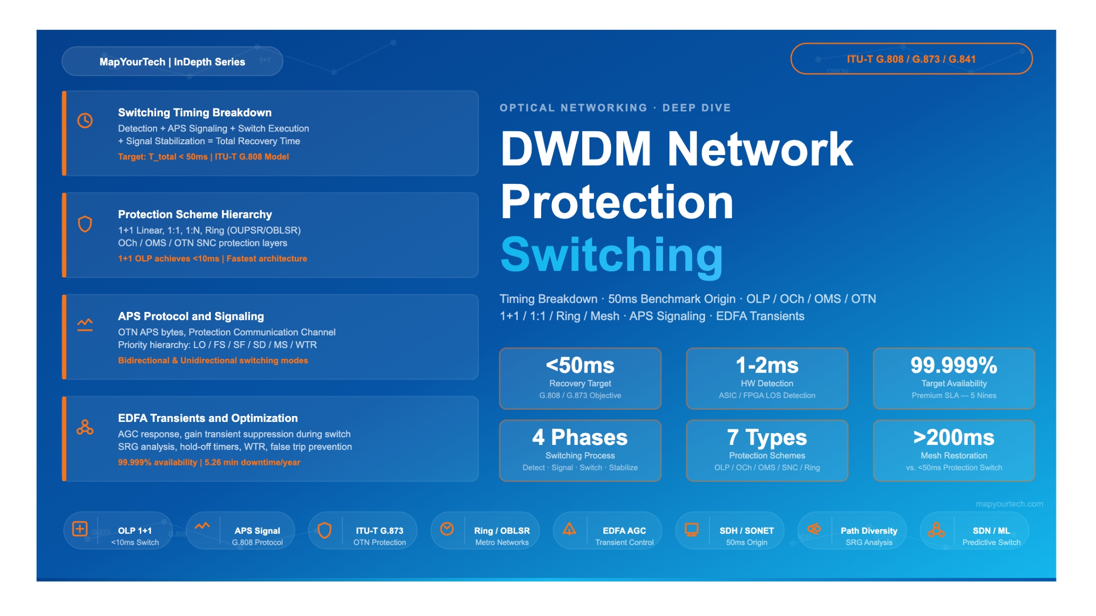
A comprehensive technical guide to protection switching timing, the engineering origin of the 50ms benchmark, and how modern optical networks achieve hitless or near-hitless recovery.

<50ms Target Recovery Time
~2ms Typical HW Detection
1+1 Fastest Scheme
99.999% Target Availability
G.873 OTN Protection Standard
>200ms Mesh Restoration Range
Section 1

Introduction

Modern telecommunications networks carry financial transactions, emergency services, media distribution, and cloud infrastructure — traffic for which even a few seconds of disruption creates measurable economic and societal impact. The optical layer, specifically Dense Wavelength Division Multiplexing (DWDM) systems, forms the backbone of this global connectivity, transporting terabits of data across continents and oceans over a single pair of fibers.

When a fiber cut, equipment failure, or signal degradation event occurs on a DWDM network, the response must be both automatic and fast. Protection switching is the engineered mechanism that achieves this: it detects the fault, coordinates the response, and moves traffic to a pre-provisioned backup path. The target for this entire sequence is 50 milliseconds — a number that appears throughout optical networking standards and service level agreements (SLAs) but whose origin and technical justification deserve careful examination.

This article covers the complete picture of sub-50ms protection switching in DWDM networks. It starts with the historical SDH/SONET roots that established the 50ms requirement, moves through a detailed timing breakdown of each phase in the switching process, surveys the principal protection architectures available at the optical and OTN layers, and closes with implementation considerations, optimization strategies, and emerging approaches that push recovery even faster. All values and standards cited are grounded in ITU-T recommendations and established engineering practice.

Scope of This Article

This guide covers optical-layer and OTN-layer protection switching. IP/MPLS fast reroute (FRR), Ethernet protection, and higher-layer recovery mechanisms are addressed only where they interact with or compare to optical protection. The primary standards references are ITU-T G.841 (SDH protection), ITU-T G.873 (OTN protection), and ITU-T G.808 (generic protection terminology).

Section 2

Historical Evolution — SDH/SONET Roots

To understand why sub-50ms protection switching matters, it is necessary to trace the requirement back to the networks that established it. The 50ms benchmark did not emerge from DWDM engineering — it was inherited from the Synchronous Digital Hierarchy (SDH) and Synchronous Optical Network (SONET) standards that dominated optical transport from the late 1980s through the 2000s.

2.1 SDH/SONET and the Birth of Fast Switching

SDH (standardized by ITU-T as G.707) and SONET (standardized by ANSI as T1.105) were designed from the start for carrier-grade voice and data transport. Their ring-based protection architectures — Bidirectional Line-Switched Rings (BLSR) and Unidirectional Path-Switched Rings (UPSR) — incorporated automatic protection switching (APS) that restored service in under 50ms following a fiber or equipment failure. This capability was essential for packetized voice: human callers experience disruptions exceeding approximately 50ms as a noticeable audio dropout. Maintaining this threshold ensured that protection switching was transparent to voice quality.

Late 1980s — Early 1990s

SONET (ANSI T1.105) and SDH (ITU-T G.707) standardized. Ring protection with 50ms APS requirement established to protect TDM voice circuits.

Mid-1990s

ITU-T G.841 defines SDH network protection ring architectures (UPSR and BLSR). The 50ms switching objective becomes a formal standard requirement.

Late 1990s — 2000s

DWDM deployment scales rapidly. Optical Layer Protection (OLP) is introduced, inheriting the 50ms target from SDH/SONET. ITU-T G.692 and G.694 define DWDM channel plans. G.808 establishes generic protection switching terminology.

2000s — 2010s

OTN (ITU-T G.709) is standardized. ITU-T G.873 extends protection switching requirements to the OTN layer, maintaining the sub-50ms objective for the 1+1 and ring protection schemes.

2010s — Present

Coherent DWDM, ROADMs, and SDN control planes mature. Hardware-accelerated detection and FPGA-based APS controllers drive switching times well below 50ms. Machine learning-based predictive switching begins emerging in research contexts.

2.2 Inheritance by DWDM and OTN

When DWDM systems began carrying aggregated wavelengths that in turn carried SDH/SONET traffic, any failure at the optical layer translated immediately into mass simultaneous failure of all the SDH circuits riding those wavelengths. To preserve the SDH end-to-end SLAs, the optical layer itself had to switch at least as fast as SDH ring protection — within 50ms. This logic drove the adoption of the 50ms target across optical layer protection schemes including Optical Line Protection (OLP), Optical Channel Protection (OCh protection), and Optical Multiplex Section Protection (OMS protection).

OTN inherited the same objective via ITU-T G.873. The standard defines protection types for the OTN hierarchy — from the Optical Channel (OCh) through the Optical Data Unit (ODU) sublayers — and stipulates that end-to-end switching must complete within 50ms for 1+1 protection schemes, consistent with G.841.

Section 3

Why 50ms? The Engineering Benchmark

The 50ms figure is not an arbitrary threshold. It rests on three converging engineering and human-factors considerations: perceptual continuity of voice, TCP timeout behavior, and synchronization slip tolerance. Understanding these justifications helps engineers design protection schemes that are correctly calibrated — fast enough to matter, without incurring unnecessary cost or complexity.

3.1 Voice Quality and Perceptual Transparency

Psychoacoustic research established that human listeners begin to perceive audio interruptions when gaps in a speech stream exceed approximately 40–60ms. SDH/SONET systems were primarily designed to carry TDM voice, and the 50ms APS requirement was set to keep protection switching perceptually transparent to telephone users. Any switching event completing within this window would not be detectable as a dropout.

3.2 TCP Retransmission and Data Service Continuity

For data services, the key consideration is TCP's retransmission timeout (RTO) behavior. While modern TCP implementations have minimum RTOs on the order of 200ms or more in many configurations, packet reordering or short packet loss events that complete well under 100ms typically do not trigger full retransmission. A protection switch completing in under 50ms is unlikely to cause TCP connections to enter a loss-recovery state, which is why financial trading networks, cloud data center interconnects, and enterprise WANs specify sub-50ms recovery as the baseline for premium SLAs.

3.3 Synchronization and Clock Stability

SDH/SONET networks use synchronization distribution hierarchies (per ITU-T G.803 for SDH). If a primary synchronization reference is lost, the receiving network element must detect the loss and revert to an alternative reference before the network clock wanders enough to cause slip events or framing errors. The timing of this process established an additional constraint that aligned well with the 50ms protection switching target.

Important context: The 50ms figure is an objective derived from SDH/SONET legacy voice requirements. Modern packet-optical networks carrying Ethernet and IP traffic do not have the same strict perceptual voice constraints. However, the 50ms target persists because it represents a commercially established SLA benchmark. Many enterprise and carrier SLAs now reference "sub-50ms" or "sub-50ms at the optical layer" regardless of the underlying traffic type.

3.4 Availability Implications

Protection switching speed directly determines the availability that a network can offer. The relationship between switching time, failure frequency, and annual downtime is straightforward: if the switching process takes 10 seconds instead of 50ms, each failure event contributes 200 times more unavailability. For a network targeting five-nines availability (99.999%, equivalent to approximately 5.26 minutes of downtime per year), fast automatic protection switching is one of the foundational mechanisms.

Table 1: Availability versus switching time for different SLA tiers

SLA Tier Target Availability Max Downtime/Year Switching Time Requirement Typical Protection Type
Premium99.999%~5.26 min<50ms1+1 multi-layer
Gold99.99%~52.6 min<50msOLP 1+1 or BLSR
Silver99.9%~8.76 hr<100msOLP 1:1
Bronze99.5%~43.8 hr<300msOLP 1:N or restoration
Best Effort99%~87.6 hr<1sMesh restoration
Section 4

Protection Switching Timing Breakdown

Achieving a sub-50ms end-to-end switching time requires a precise understanding of each phase in the switching process. The total switching time is the sum of several sequential stages, each of which must be tightly controlled. ITU-T G.808 defines the timing model for protection switching, and the industry has developed hardware and software architectures specifically to meet its constraints.

4.1 The Four-Phase Model

01

Failure Detection

Typically 1–10ms

Hardware detects Loss of Signal (LOS), Loss of Frame (LOF), BER threshold crossing, or optical power drop. ASIC or FPGA-based detection achieves the fastest times.

02

APS Signaling

Typically 3–15ms

The detecting node generates an APS message, transmits it to the far-end node via the Protection Communication Channel (PCC), and the far-end processes and acknowledges the switch request.

03

Switch Execution

Typically 5–20ms

The switch fabric or optical switch activates the protection path. For 1+1 schemes, this involves bridge-and-switch operations. Hardware switching elements respond in microseconds; system overhead accounts for the bulk of this phase.

Premium Article — Free 20% Preview

Read the Full Analysis with Premium

The remaining 80% of this article — the design numbers, trade-offs and field guidance — is part of MapYourTech Premium, along with the full premium library, courses and professional tools.


Instant access · Cancel anytime · 48-hour trial available
Sanjay Yadav

Optical Communications & Network Automation Expert | Author of 3 Books for Optical Engineers | Founder, MapYourTech

Optical networking engineer with nearly two decades of experience across DWDM, OTN, coherent optics, submarine systems, and cloud infrastructure. Founder of MapYourTech.

Follow on LinkedIn
Share:

You May Also Like

52 min read 12 0 Like The Submarine Cable Stack: Open Cables, GSNR, SDM and Power Skip to main content...
  • Free
  • July 10, 2026
32 min read 10 0 Like Coherent DSP Architecture: From ADC Samples to Client Bits MAPYOURTECH | COHERENT OPTICS DEEP...
  • Free
  • July 10, 2026
42 min read 13 0 Like Building an Optical NOC Dashboard with OpenConfig Telemetry Skip to main content MapYourTech |...
  • Free
  • July 10, 2026

Course Title

Course description and key highlights

Course Content

Course Details
