
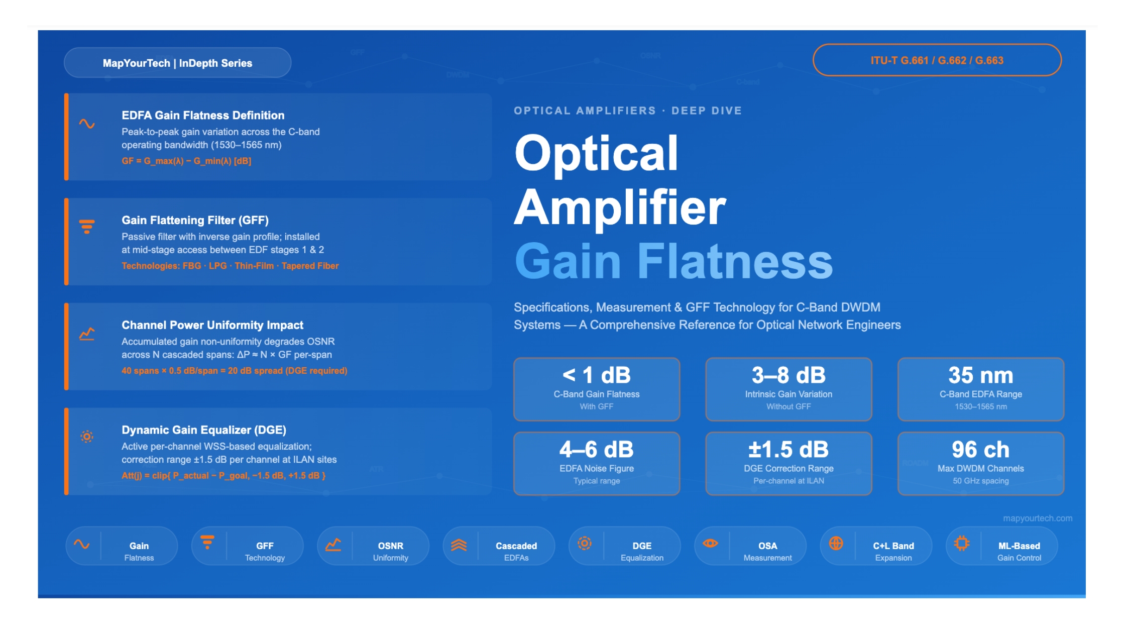

Optical Amplifier Gain Flatness:
Specifications and Measurement
A comprehensive reference for optical networking engineers covering gain flatness definition, measurement methodology, C-band EDFA specifications, channel power uniformity impacts, and gain flattening filter (GFF) technology.
spec (with GFF)
operating range
noise figure
range
at 50 GHz
correction range
1. Introduction
The Erbium-Doped Fiber Amplifier (EDFA) transformed long-haul optical networking by enabling direct optical amplification across many wavelength channels simultaneously. Operating in the C-band (1530–1565 nm), a single EDFA replaces costly per-wavelength optical-electrical-optical regenerators with a single wideband device. This capability underpins Dense Wavelength Division Multiplexing (DWDM) systems carrying anywhere from a few dozen to 96 or more channels on a single fiber.
However, erbium ions do not amplify all wavelengths equally. The natural gain spectrum of an erbium-doped silica fiber varies with wavelength — exhibiting a characteristic shape with a pronounced peak near 1530 nm, a secondary region of elevated gain around 1550–1558 nm, and a gradual roll-off toward 1565 nm. Left uncompensated, this wavelength-dependent gain creates a channel power hierarchy: channels near the gain peak receive more amplification than channels at the band edges. Over a single amplifier span this difference may be modest, but across a cascade of tens or hundreds of amplifiers in a long-haul or transoceanic system, the cumulative gain excursion causes some channels to be amplified far above their target power while others fall well below. The consequences include degraded Optical Signal-to-Noise Ratio (OSNR) on the weakest channels, increased nonlinear impairments on the strongest channels, and ultimately a reduction in achievable system capacity and reach.
Gain flatness — the degree to which an amplifier provides equal gain to all channels across its operating bandwidth — is therefore one of the most important performance parameters for EDFA-based DWDM systems. This article covers the definition, measurement, and specification of EDFA gain flatness, its practical impact on channel power uniformity, and the technology of Gain Flattening Filters (GFFs) and Dynamic Gain Equalizers (DGEs) used to manage it.
2. Defining Gain Flatness
2.1 The Gain Flatness Parameter
Gain flatness quantifies the variation in gain across an amplifier's specified operating bandwidth. The most widely used definition, and the one employed in ITU-T recommendations G.661, G.662, and G.663, expresses gain flatness as the peak-to-peak gain deviation across all wavelength channels within the operating band:
GF = Gmax(λ) − Gmin(λ)    [dB]

Where:
  G_max(λ)  = Maximum gain (dB) across the operating wavelength range
  G_min(λ)  = Minimum gain (dB) across the operating wavelength range
  GF        = Gain flatness in dB (peak-to-peak, always positive)
λ = Wavelength variable across the C-band (1530–1565 nm)- Lower GF values are better. GF = 0 dB means perfectly flat gain — all wavelengths amplified identically.
- Without a GFF, a C-band EDFA may exhibit 3–8 dB of intrinsic gain variation.
- With a well-designed GFF, GF can be reduced to below 1 dB across the full C-band.
An alternative representation sometimes used in characterization is the gain deviation or gain ripple, which expresses the departure of the measured gain at each wavelength from a reference gain value (typically the average gain or the gain at a specified operating point). This approach is more informative in situations where a gain tilt — a linear slope across the band — needs to be distinguished from higher-order gain shape errors.
dG(λ) = G(λ) − Gavg    [dB]

Where:
  G(λ)     = Actual gain at wavelength λ (dB)
  G_avg    = Average gain across the operating band (dB)
dG(λ) = Gain deviation from average at wavelength λ (dB)- dG(λ) is the quantity stored in the EDFA's ATR (Automatic Test Report) table in real deployed amplifiers.
- Per-channel gain G(λj) = Gavg + dG(λj) + Tilt contribution.
2.2 Gain Tilt as a Special Case
Gain tilt refers to a gain shape that varies monotonically across the band — higher gain at one edge and lower gain at the other. It arises from multiple physical sources: the natural slope of the erbium gain cross-section, the Stimulated Raman Scattering (SRS) transfer from shorter to longer wavelengths in the transmission fiber, and intentional tilt applied by the amplifier to pre-compensate downstream fiber tilt. ITU-T G.663 defines tilt as a specific subset of gain nonuniformity. In deployed systems, the EDFA tilt is actively managed: the amplifier applies a tilt equal in magnitude but opposite in sign to the tilt accumulated in the downstream fiber span, so that the channel power envelope arriving at the next amplifier's input is flat.
Gain Tilt in Practice: ROADM and ILAN Sites
Read the Full Analysis with Premium
The remaining 89% of this article — the design numbers, trade-offs and field guidance — is part of MapYourTech Premium, along with the full premium library, courses and professional tools.


