

Generic selectors
Exact matches only
Search in title
Search in content
Post Type Selectors
Articles
lp_course
lp_lesson
Back
HomeCoherent OpticsAmplified Spontaneous Emission (ASE) Noise in EDFA Systems
Amplified Spontaneous Emission (ASE) Noise in EDFA Systems

Amplified Spontaneous Emission (ASE) Noise in EDFA Systems

Last Updated: April 2, 2026
31 min read
133
Amplified Spontaneous Emission (ASE) Noise in EDFA Systems

Amplified Spontaneous Emission (ASE) Noise in EDFA Systems

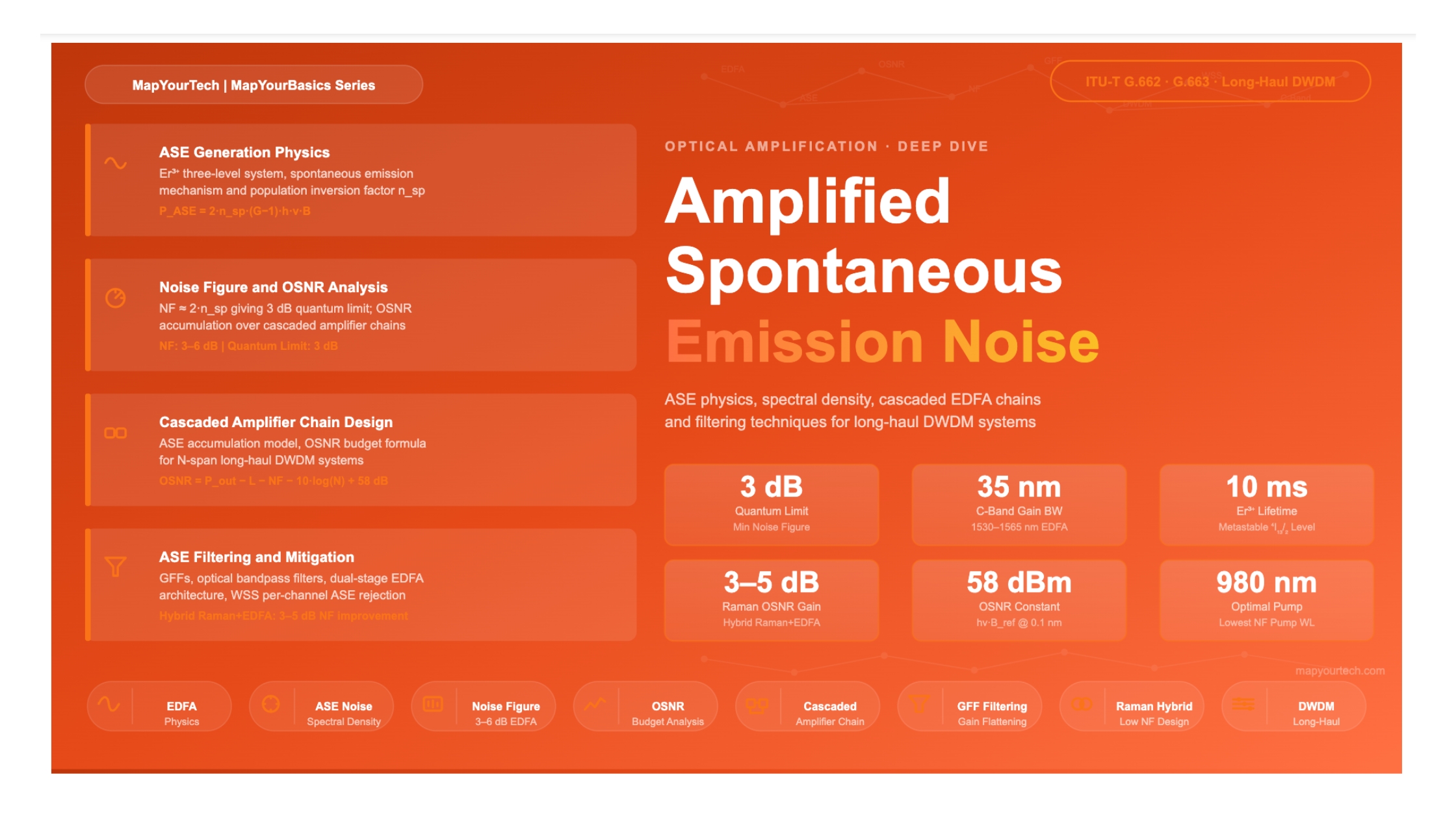
A comprehensive engineering reference covering the physics of ASE generation, noise spectral density, accumulation over cascaded amplifier chains, and filtering strategies to control the ASE noise floor.

1. Introduction

Context, relevance, and scope of ASE noise in modern optical transport

Erbium-Doped Fiber Amplifiers (EDFAs) are the workhorse of modern Dense Wavelength Division Multiplexing (DWDM) transport. By enabling optical-domain amplification across the C-band (1530–1565 nm) and L-band (1565–1625 nm), EDFAs eliminated the need for costly and bandwidth-limiting optical-electrical-optical (OEO) regeneration at every repeater site. Deployed from metro regional links of a few hundred kilometres to transoceanic submarine cables spanning thousands of kilometres, EDFAs remain the dominant amplification technology in long-haul optical networking.

Every EDFA is, however, an imperfect device. While the amplifier boosts the desired signal through stimulated emission of erbium ions, it simultaneously produces spontaneous photons that are random in phase, frequency and direction. A fraction of these spontaneous photons travel along the fiber axis and are themselves amplified by the gain medium — a process called Amplified Spontaneous Emission (ASE). ASE is the primary noise mechanism in EDFAs, and its management is central to achieving adequate Optical Signal-to-Noise Ratio (OSNR) at the receiver.

Understanding ASE is essential at every level of optical network design: from choosing pump wavelengths and EDFA configurations at the component level, to budgeting OSNR margins across multi-span transmission systems, to evaluating where optical bandpass filtering should be placed. This article covers the full picture — the quantum-mechanical origin of ASE, the mathematical framework governing its spectral density, how it accumulates over cascaded amplifier chains, and the practical filtering and system design techniques used to keep the ASE noise floor within budget.

2. Physics of ASE Generation

From erbium energy levels to photon emission pathways

2.1 The Erbium Three-Level System

The optical gain in an EDFA originates from the energy-level structure of trivalent erbium ions (Er3+) embedded in a silica glass host. When a pump laser at 980 nm or 1480 nm illuminates the erbium-doped fiber, it excites ground-state erbium ions to higher energy levels. For 980 nm pumping, ions are excited to the 4I11/2 level and then rapidly relax through non-radiative decay to the metastable 4I13/2 manifold — the upper laser level. This manifold has a relatively long excited-state lifetime of approximately 10 ms, allowing a population inversion to build up relative to the ground state 4I15/2.

The gain medium thereby functions as a three-level (980 nm pump) or quasi-two-level (1480 nm pump) laser system. Signal photons in the 1530–1565 nm range stimulate downward transitions from 4I13/2 to 4I15/2, producing identical copies of the signal photon — this is stimulated emission, and it is the desired amplification mechanism.

Figure 1: Er³⁺ Energy Levels and ASE Generation Mechanism in EDFA ⁴I₁₅/₂ — Ground State ⁴I₁₃/₂ — Metastable (≈10 ms lifetime) ⁴I₁₁/₂ — Pump Level (980 nm) 980 nm Pump Absorption Fast NR decay Stimulated Emission (1530–1565 nm) Spontaneous Emission 1480 nm Pump 1. Pump Absorption 980 nm or 1480 nm laser excites Er³⁺ ions 2. Population Inversion More ions in ⁴I₁₃/₂ than ground state Photon Emission Pathways Stimulated OR Spontaneous Stimulated Emission Coherent with signal = Desired Gain Same phase, direction, freq Spontaneous Emission Random phase & direction Amplified → ASE Noise Degrades OSNR Gain Medium Er³⁺ in SiO₂ fiber

Figure 1: Energy level transitions in Er³⁺ and the two competing photon emission pathways — stimulated emission producing signal gain and spontaneous emission producing ASE noise.

2.2 Spontaneous Emission and Its Amplification

Spontaneous emission occurs when an excited erbium ion decays to the ground state without the triggering influence of a passing signal photon. The resulting photon is emitted with a random phase and in a random direction. In free space this would be irrelevant to a guided-wave system, but within the confines of a single-mode fiber, a small fraction of these spontaneous photons couple into the guided mode and propagate along the fiber axis — both in the forward and backward directions.

Once launched into the fiber core, these spontaneous photons are indistinguishable from signal photons by the gain medium. As they travel through the inverted population, they trigger additional stimulated emission events and grow exponentially. This amplified spontaneous emission (ASE) is broadband — it spans the full gain bandwidth of the EDFA (approximately 35 nm in the C-band) — and it accumulates at the output of every amplifier stage. Because it occupies the same spectral band as the signal, optical filtering cannot easily separate ASE from the signal without also affecting signal integrity.

Key Concept: Directionality of ASE

ASE propagates in both forward (co-propagating with the signal) and backward directions. Forward ASE adds directly to the noise power that reaches the receiver. Backward ASE, if not properly suppressed by optical isolators, can re-enter the previous amplifier stage or the transmitter, causing instability or additional noise through multi-path interference. Well-designed EDFA modules include optical isolators at both input and output ports.

2.3 Stimulated vs. Spontaneous Emission: The Population Inversion Factor

The relative proportion of stimulated versus spontaneous emission is quantified by the population inversion factor nsp (also called the spontaneous emission factor or inversion parameter). It is defined as:

Population Inversion Factor

nsp = N₂ / (N₂ - N₁)

N₂ = population density of excited erbium ions (upper laser level, ⁴I₁₃/₂)

N₁ = population density of ground-state erbium ions (⁴I₁₅/₂)

When the amplifier is fully inverted (N₁ → 0), nsp → 1, which represents the quantum-noise limit.

In practice, with incomplete inversion, nsp > 1, leading to a noise figure above the 3 dB quantum limit.

A fully inverted amplifier approaches nsp = 1 and represents the best noise performance achievable — the so-called quantum noise limit. In real EDFAs, ground-state absorption is never completely eliminated, so nsp typically falls in the range of 1.2 to 2.5 depending on pump power, fiber design, and operating wavelength within the gain band. Minimizing nsp through high pump power and optimised erbium-doped fiber design is one of the primary strategies for reducing ASE noise.

3. ASE Noise Spectral Density

Quantifying ASE power — the foundational equations

3.1 The ASE Power Spectral Density Formula

The spectral power density of ASE generated by a single EDFA, measured per unit optical bandwidth, is given by a standard expression derived from the quantum theory of optical amplification:

ASE Power Spectral Density (Single Polarization)

SASE = nsp · (G - 1) · h · ν

SASE = ASE power spectral density, per polarization mode [W/Hz]

nsp = spontaneous emission factor (population inversion factor)

G = amplifier power gain (linear, not dB)

h = Planck's constant = 6.626 × 10⁻³⁴ J·s

ν = optical frequency [Hz] (e.g., 193.4 THz for 1550 nm)

This expression applies to a single polarization mode. A standard single-mode fiber supports two degenerate polarization modes, so the total ASE power spectral density, accounting for both polarizations, is:

Premium Article — Free 20% Preview

Read the Full Analysis with Premium

The remaining 80% of this article — the design numbers, trade-offs and field guidance — is part of MapYourTech Premium, along with the full premium library, courses and professional tools.


Instant access · Cancel anytime · 48-hour trial available
Sanjay Yadav

Optical Communications & Network Automation Expert | Author of 3 Books for Optical Engineers | Founder, MapYourTech

Optical networking engineer with nearly two decades of experience across DWDM, OTN, coherent optics, submarine systems, and cloud infrastructure. Founder of MapYourTech.

Follow on LinkedIn

You May Also Like

15 min read 14 0 Like Connector Types and Their Loss Budgets: SC, LC, MPO Skip to main content MapYourTech...
  • Free
  • July 11, 2026
16 min read 12 0 Like Cooled vs Uncooled Lasers: The Pluggable Power Trade-off Skip to main content MapYourTech |...
  • Free
  • July 11, 2026
16 min read 18 0 Like Automation Blast Radius: Scoping What a Bad Intent Can Touch Skip to main content...
  • Free
  • July 11, 2026

Course Title

Course description and key highlights

Course Content

Course Details
