
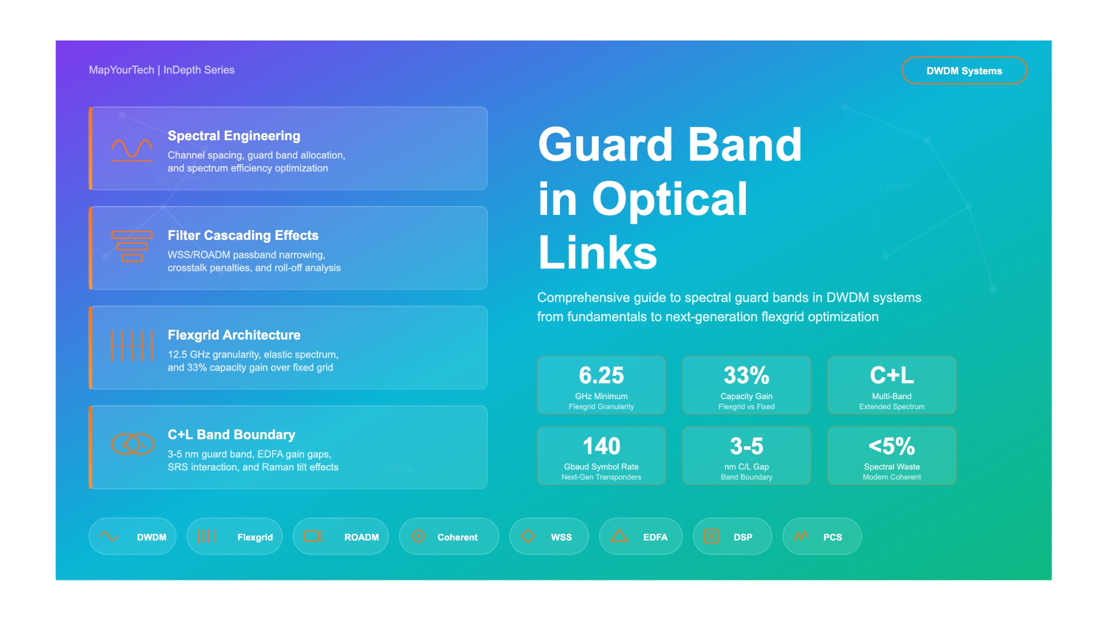

Guard Band in Optical Links: Everything About It
A comprehensive guide to spectral guard bands in DWDM systems, from fundamental principles through flexgrid optimization and future directions in ultra-dense optical networking.
1. Introduction
In every Dense Wavelength Division Multiplexing (DWDM) optical network, the available spectrum is a finite and precious resource. As traffic demand grows exponentially driven by cloud computing, AI workloads, and 5G backhaul, operators must extract every possible bit of capacity from each fiber pair. At the heart of this spectral engineering challenge lies a seemingly simple concept that carries enormous practical implications: the guard band.
The concept of guard bands extends across multiple domains within optical networking: the spectral gap between individual WDM channels, the unused band between C-band and L-band amplification windows, the guard intervals inside OFDM-based superchannel formats, and the dead zones at the edges of ROADM filter passbands. Each type has different origins, different magnitudes, and different optimization strategies. Understanding all of them is essential for anyone designing, operating, or planning modern optical transport networks.
This article provides a comprehensive examination of guard bands in optical links. It covers the physics and engineering behind why guard bands exist, how they are quantified, what determines their minimum width, and how modern technologies such as coherent detection, digital spectral shaping, and flexgrid architectures are compressing them to unlock greater capacity. Whether you are a network planner evaluating C+L band expansion, a design engineer configuring ROADM filter profiles, or a researcher working on Nyquist-WDM techniques, this guide will give you the complete picture.
2. Fundamental Concepts and Definitions
2.1 What Exactly is a Guard Band?
In the simplest terms, a guard band is the frequency (or wavelength) separation between the edge of one optical channel's occupied spectrum and the edge of the next channel's occupied spectrum. It is the "empty" region between channels where no signal energy should exist. The guard band ensures that imperfections in real-world optical components (lasers, filters, modulators, amplifiers) do not cause one channel's energy to corrupt an adjacent channel.
Formal definition: The guard band (GB) is the difference between the channel spacing and the signal bandwidth occupied by one channel. For a system with channel spacing Δf and signal baud rate Rs with roll-off factor ρ, the guard band is: GB = Δf − Rs(1 + ρ). When GB = 0, the system operates at the Nyquist limit.
Guard bands appear at several levels in an optical network. At the channel level, each WDM channel has guard bands separating it from its neighbors. At the band level, a guard band exists between the C-band and L-band amplification windows where neither EDFA operates efficiently. At the ROADM node level, the finite roll-off of WSS filtering demands guard bands between channel groups assigned to different WSS ports. And in OFDM-based superchannels, guard intervals (cyclic prefixes) protect against inter-symbol interference.
2.2 Guard Band vs. Channel Spacing
A common source of confusion is the difference between "channel spacing" and "guard band." Channel spacing (typically 50 GHz, 75 GHz, or 100 GHz in fixed-grid systems) is the frequency distance between the center frequencies of two adjacent channels. The guard band is the unused portion of that spacing that does not carry signal energy. The relationship is straightforward but critical:
Guard Band = Channel Spacing (Δf) − Signal Bandwidth (Bsignal)

Where:
  Bsignal = Rs × (1 + ρ)
  Rs     = Symbol rate (baud rate) in GHz
  ρ      = Roll-off factor of pulse shaping filter (0 to 1)

-- Example: 100G DP-QPSK at 32 Gbaud, roll-off = 0.2, 50 GHz grid --
  Bsignal = 32 × (1 + 0.2) = 38.4 GHz
  Guard Band = 50 − 38.4 = 11.6 GHz

-- Example: 400G DP-16QAM at 69 Gbaud, roll-off = 0.1, 75 GHz grid --
  Bsignal = 69 × (1 + 0.1) = 75.9 GHz
  Guard Band = 75 − 75.9 = -0.9 GHz (NEGATIVE: spectral overlap!)
The second example above illustrates a critical challenge in modern high-baud-rate systems: the signal bandwidth can exceed the allocated channel spacing, creating a negative guard band. This is the regime of super-Nyquist WDM, where controlled inter-channel crosstalk is accepted and managed through advanced DSP algorithms. As shown in research on super-Nyquist WDM systems, when the signal baud rate exceeds the channel spacing, additional algorithms for crosstalk equalization become essential to maintain acceptable performance.
Read the Full Analysis with Premium
The remaining 89% of this article — the design numbers, trade-offs and field guidance — is part of MapYourTech Premium, along with the full premium library, courses and professional tools.


