Generic selectors
Exact matches only
Search in title
Search in content
Post Type Selectors
Articles
lp_course
lp_lesson
Back
HomeAnalysisInteroperability Between Standard Single-Mode Fiber and Hollow Core Fiber
Interoperability Between Standard Single-Mode Fiber and Hollow Core Fiber

Interoperability Between Standard Single-Mode Fiber and Hollow Core Fiber

Last Updated: April 2, 2026
63 min read
106
Interoperability Between Standard Single-Mode Fiber and Hollow Core Fiber - Part 1
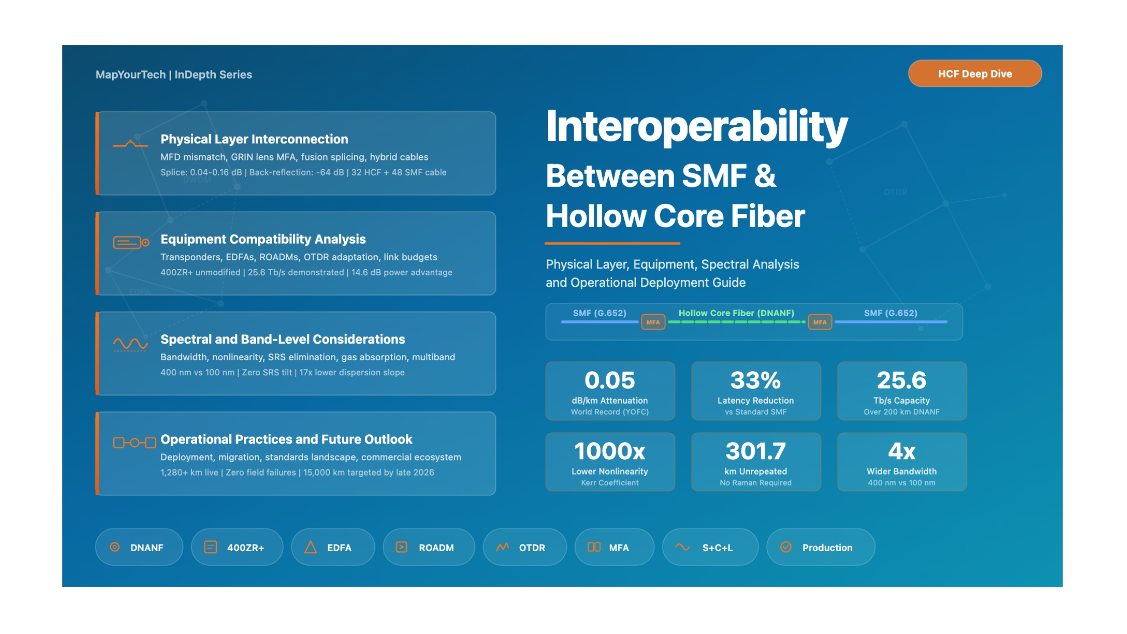
MapYourTech | InDepth Series

Interoperability Between Standard Single-Mode Fiber and Hollow Core Fiber

A Comprehensive Engineering Guide to Physical Layer Compatibility, Optical Properties, and Splicing Challenges When Integrating HCF into Existing SMF Infrastructure

1.1 Introduction: The Integration Challenge

Hollow Core Fiber (HCF) represents one of the most significant advances in optical fiber technology since the development of low-loss single-mode fiber in the 1970s. By guiding light through air rather than glass, HCF delivers a fundamentally different set of optical characteristics: approximately 33% lower latency, near-zero nonlinear effects, 7x lower chromatic dispersion, and an ultra-wide transmission window spanning over 400 nm compared to the approximately 100 nm usable in conventional silica fiber. With attenuation records now reaching 0.05 dB/km at OFC 2025, HCF has surpassed the Rayleigh scattering limit that caps standard Single-Mode Fiber (SMF) performance at approximately 0.14 dB/km.

However, the global fiber optic infrastructure represents over 5 billion kilometers of installed SMF. The transition to HCF will not happen overnight, and it will not involve wholesale replacement of existing plant. The practical reality is a period of coexistence and interoperability where HCF segments must interface seamlessly with existing SMF-based equipment, including transponders, amplifiers, ROADMs, patch panels, and test instruments. This creates a complex engineering challenge at multiple layers of the network stack.

The following analysis addresses every aspect of the interoperability question that optical networking professionals face when evaluating or deploying HCF alongside existing SMF infrastructure -- from fiber-level physical compatibility and mode field diameter mismatch, through equipment compatibility with transponders, amplifiers, and ROADMs, to spectral and band-level considerations, and operational practices for mixed-fiber networks.

1.2 Fundamental Physical Differences: SMF vs. HCF

Before addressing interoperability at the equipment level, engineers must understand the fundamental physical differences between SMF and HCF. These differences determine every aspect of how the two fiber types interact when connected together, and which network components require adaptation.

1.2.1 Light Guidance Mechanism

In standard SMF (ITU-T G.652), light propagates through a solid silica glass core (typically 8-10 micrometers in diameter) surrounded by a doped cladding of slightly lower refractive index. The guidance mechanism is Total Internal Reflection (TIR), a well-understood and inherently broadband effect that depends solely on the refractive index contrast between core and cladding. The light's electric field interacts strongly with the glass matrix, which gives rise to all of SMF's familiar characteristics: Rayleigh scattering, Kerr nonlinearity, stimulated Brillouin scattering, chromatic dispersion of approximately 17 ps/nm/km at 1550 nm, and a propagation speed of approximately 2 x 10⁸ m/s (roughly 67% the speed of light in vacuum).

In modern anti-resonant HCF (specifically Nested Anti-resonant Nodeless Fiber, or NANF, and its evolution, Double-Nested NANF or DNANF), light propagates through an air-filled core typically 25-35 micrometers in diameter. The core is surrounded by a cladding structure consisting of thin-walled silica capillaries arranged in a single ring around the core. The guidance mechanism is anti-resonant reflection: the thin glass walls of the cladding tubes act as Fabry-Perot-like resonators that become highly reflective at wavelengths where anti-resonance conditions are met. Because less than 0.01% of the optical power propagates in the glass, the fiber exhibits virtually zero nonlinearity, propagation at approximately 3 x 10⁸ m/s (near-vacuum speed of light), and chromatic dispersion of only 2-4 ps/nm/km.

Standard SMF (G.652) Cladding: 125 um Core Core: 8-10 um (solid silica) Properties Guidance: TIR Core: Solid glass MFD: ~10.4 um @ 1550nm Loss: 0.17-0.20 dB/km CD: ~17 ps/nm/km Latency: ~4.9 us/km Nonlinearity: 1.2 W-1km-1 Bandwidth: ~100 nm (C+L) neff: ~1.468 Backscatter: -80 dB/m Band-Limited by Silica Material Properties Rayleigh scattering sets loss floor at ~0.14 dB/km OH absorption peak limits E-band usage Infrared absorption rises beyond ~1625 nm Usable: O (1260-1360), S (1460-1530), C (1530-1565), L (1565-1625) nm Hollow Core NANF/DNANF Cladding: ~125 um Air Core: 25-35 um AIR Properties Guidance: Anti-Resonant Reflection Core: Air/vacuum MFD: ~17-24 um @ 1550nm Loss: 0.05-0.17 dB/km (record) CD: ~2-4 ps/nm/km (7x lower) Latency: ~3.3 us/km (33% lower) Nonlinearity: ~5x10⁻⁴ W-1km-1 Bandwidth: ~400+ nm (multi-band) neff: ~1.000 (air) Backscatter: 40 dB lower than SMF Not Band-Limited by Material -- Limited by Structure No Rayleigh scattering floor -- loss can go below 0.1 dB/km No OH absorption peak -- continuous low-loss spectrum Wall thickness tunes operating band via anti-resonance Demonstrated: 66 THz window from ~700 nm to beyond 2400 nm

Figure 1: Structural comparison between standard SMF (G.652) and Hollow Core NANF/DNANF fiber, highlighting the fundamental physical differences that drive interoperability challenges.

1.2.2 The Interoperability Parameters That Matter

From the extensive differences listed above, a subset directly affects interoperability at the fiber junction -- the physical point where SMF meets HCF. These are the parameters that determine whether the transition between fiber types introduces acceptable or unacceptable signal degradation.

Table 1: Critical Interoperability Parameters at the SMF-HCF Junction
Parameter SMF-28 (G.652.D) Modern NANF/DNANF Interoperability Impact
Mode Field Diameter (MFD) 10.4 um (1550 nm) 17-24 um (1550 nm) Major: 1.0-5.0 dB coupling loss without adaptation
Numerical Aperture (NA) 0.12-0.14 ~0.02-0.04 Moderate: Affects coupling geometry
Refractive Index (core) ~1.468 ~1.000 (air) Major: Creates 3.5% Fresnel reflection (-14.7 dB)
Mode Shape Near-Gaussian circular Near-Gaussian (NANF better than PBGF) Low: Good overlap achievable with MFD matching
Cladding Diameter 125 um ~125 um (matched) Low: Standard alignment possible
Coating Diameter 242 um (typical) ~200-250 um (varies) Low: Compatible with standard stripping tools
Core Structure Solid silica (fused) Hollow (air-filled microstructure) Major: Susceptible to collapse during fusion splicing
Temperature Sensitivity Standard glass properties 14.5x lower thermal sensitivity Low: Beneficial for network stability

1.3 Mode Field Diameter Mismatch and Its Consequences

The most significant physical barrier to direct SMF-HCF interconnection is the Mode Field Diameter (MFD) mismatch. Standard SMF-28 has an MFD of approximately 10.4 micrometers at 1550 nm, while modern NANF designs typically have an MFD of 17-24 micrometers. This factor-of-two difference in mode size means that a direct butt-coupling between the two fibers will result in a large fraction of the optical power either being scattered into cladding modes (when coupling from HCF to SMF, since the HCF mode is larger than the SMF core can capture) or exciting higher-order modes (when coupling from SMF to HCF, since the small input spot does not fill the HCF core efficiently).

1.3.1 Quantifying the Coupling Loss

The coupling loss between two single-mode fibers with mismatched MFDs can be estimated using the Gaussian beam overlap integral. For two fibers with MFDs w1 and w2, the coupling efficiency is given by:

Coupling Loss (dB) = -10 x log10 [ (2 x w1 x w2) / (w12 + w22) ]2

Where:
  w1 = MFD of fiber 1 (e.g., SMF-28 = 10.4 um)
  w2 = MFD of fiber 2 (e.g., NANF = 22 um)

-- Worked Example: SMF-28 to typical NANF --
  Loss = -10 x log10 [ (2 x 10.4 x 22) / (10.42 + 222) ]2
       = -10 x log10 [ 457.6 / 592.16 ]2
       = -10 x log10 [ 0.7727 ]2
       = -10 x log10 [ 0.597 ]
       = 2.24 dB per interface

-- For a bidirectional link with two junctions: ~4.5 dB total from MFD mismatch alone

This 2+ dB loss at every SMF-HCF junction is clearly unacceptable for production networks. Adding 4-5 dB of connector loss to an optical link budget that may already be operating with only a few dB of margin would render many deployed spans non-functional. This is precisely why Mode Field Adapters (MFAs) are essential for any practical HCF deployment.

1.3.2 Higher-Order Mode Excitation

Beyond the raw coupling loss, MFD mismatch at the junction can excite Higher-Order Modes (HOMs) within the HCF. While modern NANF designs are engineered to be effectively single-mode through differential mode loss (the cladding structure is highly lossy for HOMs), any power coupled into HOMs at the input junction will propagate for some distance before being sufficiently attenuated. This residual HOM content creates two problems. Multi-Path Interference (MPI) arises from the beating between the fundamental mode and weakly-propagating HOMs, creating noise at the receiver. Additionally, Differential Mode Delay (DMD) causes the HOM component to arrive at a different time than the fundamental mode, potentially causing inter-symbol interference in high-baud-rate systems.

Careful launch conditioning through proper Mode Field Adaptation is therefore important not only for minimizing insertion loss but also for ensuring clean fundamental-mode excitation into the HCF.

1.4 Splicing and Connectorization: Bridging Two Worlds

The practical challenge of physically joining HCF to SMF has been one of the most actively researched areas in the HCF ecosystem. Multiple approaches have been developed, each with distinct trade-offs in terms of insertion loss, return loss, reliability, hermeticity, and field-deployability.

1.4.1 Fusion Splicing: The Temperature Problem

Standard fusion splicing of solid-core fibers involves heating both fiber ends to temperatures exceeding 2000 degrees C, causing the glass to melt and fuse together. This process is well-understood and reliable for SMF-to-SMF joints, routinely achieving splice losses below 0.05 dB. However, applying standard arc fusion to HCF creates a fundamental problem: the high temperatures cause the delicate microstructured cladding of the HCF to collapse. The thin-walled capillary tubes that form the anti-resonant cladding structure soften and deform, destroying the light-guiding mechanism near the splice point and resulting in catastrophic insertion losses of several dB or complete signal extinction.

Overcoming this challenge has required entirely new splicing approaches. Specialized fusion splicers have been developed with features specifically designed for HCF. The Furukawa Electric FITEL S185PMROF splicer introduced three-electrode "Ring-of-Fire" technology that provides more uniform, controlled heating. The newer S185EVROF model, launched at Laser World of Photonics 2025, combines end-view and Ring-of-Fire capabilities specifically for hollow core fiber. These splicers employ a "tack-sweep-pulse" arc fusion technique with 165 kPa core pressurization during splicing to prevent tube collapse, achieving a median splice loss of 0.05 dB in under 120 seconds with reported 100% success rates for HCF-to-HCF splices.

1.4.2 Mode Field Adapters: The GRIN Lens Solution

The most widely adopted approach for achieving low-loss SMF-to-HCF interconnection involves inserting a Mode Field Adapter (MFA) between the two fiber types. The most successful MFA designs use a short segment of Graded-Index (GRIN) multimode fiber, typically OM1 type with a length of approximately 0.295 mm, fusion-spliced to the end of the SMF. This GRIN fiber segment acts as a miniature lens, expanding the SMF mode field from 10.4 micrometers to match the larger HCF mode of 17-24 micrometers.

Research teams at Czech Technical University developed a fiber-array-based interconnection technique that uses these GRIN mode field adapters within a precision V-groove assembly. The HCF is placed in a separate fiber array, and the two arrays are aligned and glued together at temperatures below 80 degrees C (a "cold splice" technique that avoids any risk of microstructure collapse). This approach has achieved insertion losses below 0.5 dB with return loss better than -35 dB using improved anti-reflection coatings. Critically, this technique also enables the deposition of optical coatings on the fiber end-faces, which is essential for suppressing back-reflections at the glass-air interface.

Figure 2: SMF-to-HCF Interconnection Methods A) Direct Butt-Coupling (Without Adapter) SMF HCF (Air Core) ~2-5 dB Loss MFD mismatch: 10.4 um vs 17-24 um Fresnel reflection: -14.7 dB return loss NOT ACCEPTABLE for production B) GRIN Mode Field Adapter SMF GRIN AR Coat HCF (matched MFD) 0.15-0.30 dB GRIN lens expands MFD from 10.4 to ~20 um AR coating: return loss better than -40 dB PRODUCTION-READY solution C) Pre-Terminated Patch Tail (Plug-and-Play) LC/SC SMF MFA HCF Cable LC/SC End-to-End: < 0.3 dB per connector Standard LC/FC/SC connectors on both ends Factory-optimized MFA splices inside Plugs directly into existing SMF patch panels Used in Microsoft Azure & euNetworks deployments HCF-SMF Splice Requirements for Production Networks Insertion Loss ≤ 0.25 dB Per splice interface Return Loss ≤ -40 dB Critical for coherent systems Hermeticity Sealed against dust & moisture Prevents core contamination Reliability ≥ 20 years Mechanical strength + long-term stability Field Results (Microsoft Azure Deployment, 2025): Mean splice loss: 0.16 dB | Best individual splice: 0.04 dB | Zero field failures since deployment | Compatible with standard DWDM equipment

Figure 2: Three approaches to SMF-HCF interconnection, from impractical direct coupling to production-ready connectorized patch tails deployed in live networks.

1.4.3 Commercial Connectorization Solutions

For practical network deployment, pre-terminated "plug-and-play" HCF patch tails have emerged as the preferred solution. These assemblies contain a length of HCF with factory-optimized MFA splices to SMF pigtails at each end, terminated with standard LC, FC, or SC connectors. This approach offers several key advantages for operators. The SMF-compatible connectors on both ends mean the HCF link plugs directly into existing patch panels and equipment without modification. Factory-controlled MFA optimization ensures consistent, low-loss interconnection. The sealed construction prevents dust and moisture ingress into the hollow core. And field technicians work only with familiar SMF connectors -- no specialized HCF handling skills are required at the patch panel.

Linfiber Technology has commercialized pluggable HCF-SMF connectors achieving under 0.3 dB insertion loss with standard LC/FC/SC compatibility. Their designs employ angle-cleaving at 4.5 degrees with interferometer verification and precise offset positioning, achieving -64 dB back-reflection -- the first sub-60 dB demonstration, which is critical for coherent transmission systems sensitive to reflections.

Microsoft's Azure deployments use exactly this approach. Inside the data center, connectorized HCF-specific patch tails interface between the HCF transmission cable and SMF-based active and passive equipment. Each patch tail contains two SMF-compatible connectors coupled to the HCF cable through internal MFA splices. These terminate to standard patch panels and mate directly with existing DWDM equipment.

1.5 Back-Reflection Management at the Glass-Air Interface

When light transitions from the solid silica core of SMF (refractive index approximately 1.468) into the air core of HCF (refractive index approximately 1.000), the large refractive index discontinuity at the glass-air boundary creates a strong Fresnel reflection. The reflected power can be calculated from the Fresnel equation:

Reflectance (R) = [ (n1 - n2) / (n1 + n2) ]2

Where:
  n1 = refractive index of silica = 1.468
  n2 = refractive index of air = 1.000

R = [ (1.468 - 1.000) / (1.468 + 1.000) ]2
  = [ 0.468 / 2.468 ]2
  = 0.036  (3.6% of optical power reflected)

Return Loss = -10 x log10(0.036) = -14.4 dB

-- This -14.4 dB return loss is SEVERE for coherent systems
-- Coherent transponders typically require < -40 dB return loss
-- Without mitigation, this reflection will degrade receiver performance

A -14.4 dB return loss is approximately 25 dB worse than the minimum required by most coherent transponder specifications. These reflections feed back into the transmitter laser, causing phase noise, frequency instability, and increased relative intensity noise (RIN). At the receiver, reflected power creates spurious beating products that degrade the signal constellation and increase bit error rate.

1.5.1 Mitigation Strategies

Several complementary strategies are used to manage back-reflections at SMF-HCF interfaces. Anti-Reflection (AR) coatings can be deposited on the fiber end-faces when using the cold-splice (fiber-array) interconnection technique. These thin-film coatings reduce the Fresnel reflection from -14.4 dB to better than -40 dB. Early results demonstrated return loss improvement from -14.7 dB to -42.5 dB with AR coating. Angle-cleaving the fiber ends at 4.5 degrees directs the reflected light away from the guided mode, achieving back-reflection levels of -64 dB. This technique has been successfully commercialized by Linfiber. Additionally, GRIN mode field adapters inherently provide some suppression of back-reflections by creating a gradual transition rather than an abrupt index change, with measured return loss of -24 dB or better even without additional coatings.

Critical Handling Requirement

The cleaning of cut but not sealed HCF with liquid solvents (isopropyl alcohol, acetone, etc.) is strictly forbidden. The solvent would impregnate all voids in the microstructure and the fiber would permanently lose its optical properties. Cleaving and splicing must be conducted in a dust-free, low-humidity environment, because the slightly lower pressure inside the fiber can draw dust and moist air into the core, increasing fiber loss.

1.6 Hybrid Cable Architectures for Transition Networks

A practical approach to introducing HCF into existing networks is the hybrid cable design, which packages both HCF and SMF strands within a single cable structure. Microsoft's Azure deployments use exactly this architecture. Their latest metro deployment cables contain 32 HCF strands and 48 SMF strands within the same cable jacket, installed using conventional blown-installation methods through pre-existing conduit infrastructure.

This hybrid approach offers several operational advantages. Engineers can deploy HCF and SMF simultaneously through a single installation activity, reducing civil works costs. Traffic can be migrated gradually from SMF to HCF strands as confidence and equipment compatibility are validated. The SMF strands provide a fallback path if HCF-specific issues arise. And the existing conduit infrastructure remains unchanged -- HCF cables are designed for standard blown-installation methods using high-pressure air from a compressor to push the cable into the conduit.

The HCF outside-plant (OSP) cables have been specifically developed for outdoor use in harsh environments without degrading the fiber's propagation properties. The cable technology uses loose-tube construction to isolate the HCF from external mechanical stress (bending, crushing, vibration), which is particularly important given that HCF can be more sensitive to micro-bend and macro-bend effects than standard SMF. The cables pass harsh environment testing over the temperature range from -40 degrees C to +80 degrees C.

Custom cable joint enclosures have been developed for the splicing points along the route. These enclosures organize the multiple HCF splices and are placed in underground chambers at intervals of a few hundred meters. Image evidence from field deployments shows these enclosures with HCF spliced on multiple splice tray layers, protected by colored tubes for fiber identification. Inside the data center, the HCF cable terminates to connectorized patch tails mounted on standard patch panels.

Premium Article — Free 21% Preview

Read the Full Analysis with Premium

The remaining 79% of this article — the design numbers, trade-offs and field guidance — is part of MapYourTech Premium, along with the full premium library, courses and professional tools.

Instant access · Cancel anytime · 48-hour trial available
Sanjay Yadav

Optical Communications & Network Automation Expert | Author of 3 Books for Optical Engineers | Founder, MapYourTech

Optical networking engineer with nearly two decades of experience across DWDM, OTN, coherent optics, submarine systems, and cloud infrastructure. Founder of MapYourTech.

Follow on LinkedIn
Share:

You May Also Like

15 min read 3 0 Like Connector Types and Their Loss Budgets: SC, LC, MPO Skip to main content MapYourTech...
  • Free
  • July 11, 2026
16 min read 4 0 Like Cooled vs Uncooled Lasers: The Pluggable Power Trade-off Skip to main content MapYourTech |...
  • Free
  • July 11, 2026
16 min read 5 0 Like Automation Blast Radius: Scoping What a Bad Intent Can Touch Skip to main content...
  • Free
  • July 11, 2026

Course Title

Course description and key highlights

Course Content

Course Details