
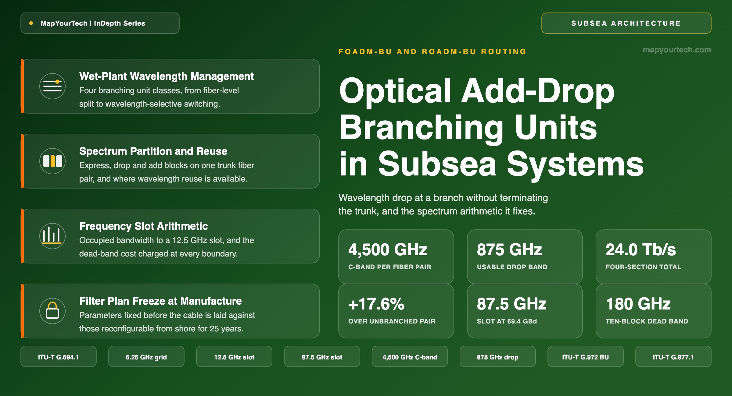
Optical Add-Drop Branching Units and Wavelength Routing in Subsea Networks
Wavelength drop at a branch without terminating the trunk, filter plans fixed at manufacture, and the spectrum arithmetic that governs later capacity upgrades on the trunk.
A network is designed once and operated for twenty years.
What You Will Learn
- Define an optical add/drop branching unit and its four component quantities — trunk express band, drop band, add band and dead band — from the anatomy of Figure 1.
- Convert a symbol rate to occupied bandwidth and to the next 12.5 GHz flexible-grid slot, checking 69.4 GBd against an 87.5 GHz slot per ITU-T G.694.1.
- Quantify what a band boundary costs in spectrum: 6.25 to 20 GHz per transition, reaching 180 GHz across a ten-band plan at the 20 GHz allowance.
- Compute carrier count and stranded spectrum inside a fixed 900 GHz drop band across four carrier generations, from 0 GHz stranded at 87.5 GHz slots to 125 GHz at 150 GHz slots.
- Read the three digital line sections a bidirectional OADM-BU creates on one trunk fiber pair, and the 24.0 Tb/s delivered at a 20% drop fraction in Figure 11.
- Select among bidirectional, unidirectional and three-degree branch configurations using the fiber-pair counts and wavelength-reuse constraints of Table 2.
- Separate the parameters frozen at manufacture from those reconfigurable from shore, using the freeze-point set of Table 5.
- Anchor branch acceptance to the open-cable parameter set of ITU-T G.977.1: branching unit count, insertion loss in decibels, and span location.
1. Introduction
A branching unit is a three-port pressure vessel sitting on the seabed where a trunk cable meets a branch cable, splicing both the optical fibers and the high-voltage power conductors of all three cable ends. The simplest version, the full fiber drop branching unit (FFD-BU), connects whole fiber pairs between any two of the three cables and contains no optical filtering at all (standard-specified definition, ITU-T G.972). Every fiber pair it hands to the branch leaves the trunk entirely. On a cable serving five landing points that accounting adds up quickly: a station needing 2 Tb/s receives a whole fiber pair capable of 20 Tb/s, and the trunk loses that pair for its full length.
The optical add/drop branching unit removes that quantization. Rather than routing whole fiber pairs, it partitions the optical spectrum of a single trunk fiber pair, sending one block of frequencies down the branch while the remainder continues along the trunk untouched. ITU-T G.972 fixes two classes by name: the fixed optical add/drop multiplexing branching unit (FOADM-BU), in which the added, dropped and passed-through wavelengths are fixed, and the reconfigurable optical add/drop multiplexing branching unit (ROADM-BU), in which they can be modified in service (standard-specified, ITU-T G.972). One trunk fiber pair equipped with an OADM-BU meets the same traffic demand that two fiber pairs and an FFD-BU would need, which is where the cost argument starts and where every subsequent constraint follows from.
The constraint that makes this an engineering problem rather than a procurement one is that the partition is decided before the cable is manufactured. Filter arrangements in an OADM module are determined in advance of system construction from contract-specific traffic requirements (industry-reported design practice). Once the module is potted, pressure-tested and laid in 4,000 m of water, the band edges are where they are. A capacity upgrade fifteen years later runs coherent carriers whose occupied bandwidth bears no relation to the transponder generation that set the band widths, and the carriers must fit inside boundaries chosen by a planner who had no way to know what a 2040 modem would look like.
Two forces have made that mismatch sharper. Carrier slot widths have grown from 50 GHz for early 100 Gb/s transponders at roughly 33 GBd to 150 GHz for the widest carriers now planned, so a band that once held an integer number of channels now strands a remainder. And spectrum itself has become a traded product: a spectrum-sharing user buys a frequency window from the provider's spectrum management block and fills it from their own line terminal, which means the band edges written into a wet-plant filter plan reappear years later as the boundaries of a commercial allocation. A branching unit with filtering capability supplies different frequency ranges for express and drop paths, so a user may receive multiple non-contiguous spectrum blocks rather than one (industry-reported, spectrum-sharing working group practice).
Wavelength-selective switch technology changed what can be renegotiated after the fact. A WSS-based ROADM-BU reconfigures band edges from shore in steps of 6.25 or 12.5 GHz aligned to the ITU grid (industry-reported device capability), and its filter transitions are sharp enough that guard bands between add/drop bands are close to eliminated compared with fixed passband filters. Reconfigurable units carrying preselected filters and optical switches entered subsea service around 2015; WSS-based units became the industry choice for systems in negotiation around 2018 and reached service around 2021 (industry-reported deployment timeline). That does not retire the fixed unit. Fixed filters carry lower component complexity and higher predicted reliability than a WSS, and on branches whose traffic profile is genuinely static, a coupler-based no-wavelength-reuse OADM remains the cheapest way to reach an island or an offshore platform.
The scope here is the spectrum mechanics of add/drop at a subsea branch: how a partition is defined, what a band boundary costs in gigahertz, how wavelength reuse recovers capacity that a naive drop would waste, and how a filter plan frozen at manufacture governs the capacity available on the trunk at every later upgrade. The boundary conditions are repeatered systems on dispersion-unmanaged fiber, C-band or C+L, with coherent transponders. Repeaterless systems, dispersion-managed legacy plant and fiber-pair switching units appear only where they change the spectrum argument.
ITU-T uses FOADM-BU and ROADM-BU; vendor and operator documentation more often writes OADM BU and ROADM BU, and treats "wavelength management unit" as the generic term for the filtering block regardless of technology. All three name the same functional element. The ITU-T forms appear here wherever a definition is being stated, and the generic term appears where the technology is unspecified. Related architecture is covered in the branching unit fundamentals walkthrough.
One structural point governs everything below. A branching unit does not create capacity; it decides where existing capacity lands. Every gigahertz dropped at a branch is a gigahertz the trunk no longer carries end to end, plus a dead band on each side of the transition that carries nothing anywhere. The design question is never whether the drop costs trunk capacity — it always does — but whether the three digital line sections the partition creates are worth more than the one it replaces, and whether the boundary positions survive three transponder generations. Both questions reduce to arithmetic that a planner can run before signing a supply contract, and Sections 6 and 8 run it.
Takeaway: An OADM-BU trades a fixed, unrecoverable spectrum partition for the ability to serve a branch station without surrendering a whole fiber pair. The trade is favorable whenever branch demand sits well below one fiber pair of capacity, and it becomes unfavorable when carrier slot widths drift far enough from the manufactured band widths that a growing remainder of each band cannot hold another carrier.
2. Optical Add/Drop Branching Unit Definitions and Component Terms
An optical add/drop branching unit is a submerged three-port assembly that divides the optical spectrum carried on one trunk fiber pair into a block routed to a branch cable and a remainder that continues along the trunk. Spectrum is measured in gigahertz of optical bandwidth, positioned by nominal central frequency in terahertz. The unit performs no electrical regeneration and no wavelength conversion; it only selects frequency ranges by optical filtering and directs each to a port.
Four quantities describe any such partition, and confusing any two of them produces a filter plan that cannot be built. The trunk express band is the frequency range that passes through the unit from trunk input to trunk output without leaving the trunk cable. The drop band is the range extracted from the trunk input and delivered to the branch cable toward the branch station. The add band is the range accepted from the branch station and inserted into the trunk output. The dead band is the range at each transition between two adjacent blocks routed to different ports, wide enough to accommodate the filter roll-off, in which no carrier can be placed in any direction.
Read the Full Analysis with Premium
The remaining 88% of this article — the design numbers, trade-offs and field guidance — is part of MapYourTech Premium, along with the full premium library, courses and professional tools.
You May Also Like

-
Free
-
August 22, 2026

-
Premium
-
August 22, 2026

-
Premium
-
August 22, 2026