
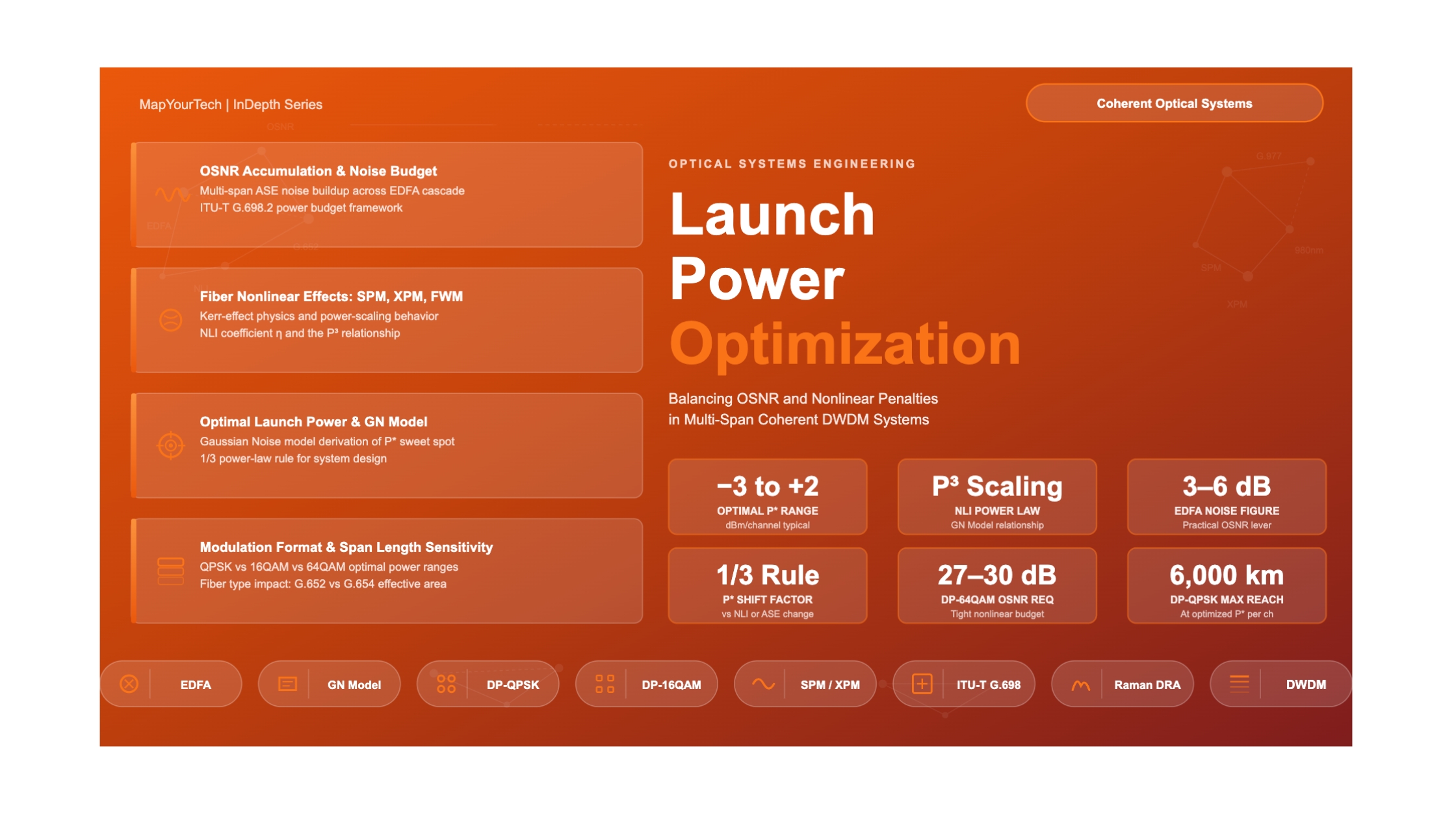

Optical Launch Power Optimization:
Balancing OSNR and Nonlinear Penalties
A comprehensive guide to finding the optimal launch power per channel — where amplifier noise, fiber nonlinearities, span length, and modulation format all converge to define the transmission sweet spot.
1. Introduction
Every optical engineer deploying a DWDM system faces the same fundamental tension: launch more power per channel and the signal arrives at the receiver with a healthy signal-to-noise ratio, but at the cost of distortion caused by fiber nonlinearities. Launch too little power and the signal is clean but drowned in amplifier noise accumulating across span after span. The solution — optimal launch power — sits at the crossing point of these two opposing forces, and finding it accurately is one of the most consequential decisions in optical link engineering.
This article builds the complete picture from first principles. It covers the physics of optical signal-to-noise ratio (OSNR) accumulation in multi-span amplified systems, explains each category of fiber nonlinear impairment and how each responds to changes in launch power, derives the concept of optimal launch power, and then shows how this optimum shifts as span length, modulation format, fiber type, and amplifier noise figure change. The Gaussian Noise (GN) model framework, which has become the standard analytical tool for this problem, is explained in accessible terms. Practical engineering methods — including worked calculations and real-world case studies — are provided throughout.
Engineers working with 100G through 800G coherent systems, network planners sizing long-haul or submarine links, and students building their optical systems knowledge will all find actionable content here.
2. OSNR Fundamentals in Multi-Span Amplified Systems
2.1 What OSNR Measures and Why It Matters
The Optical Signal-to-Noise Ratio (OSNR) quantifies the ratio of signal power in a channel to the optical noise power within a reference bandwidth. In practice, this reference bandwidth is 0.1 nm (approximately 12.5 GHz at the C-band center), and OSNR is measured at the receiver input before the coherent digital signal processor (DSP).
OSNR directly governs the bit-error rate (BER) of the received signal. Higher-order modulation formats require significantly higher OSNR to achieve the same BER because their constellation points are spaced more closely together. The relationship between OSNR requirements and modulation format is approximately:
Table 1: Minimum Required OSNR per Modulation Format (reference bandwidth 0.1 nm)
| Modulation Format | Typical Line Rate | Min. OSNR Required | Spectral Efficiency | Reach Sensitivity |
|---|---|---|---|---|
| DP-BPSK | 40G / 100G | ~10–12 dB | 2 b/s/Hz | Lowest |
| DP-QPSK | 100G / 200G | ~13–15 dB | 4 b/s/Hz | Low |
| DP-8QAM | 200G / 300G | ~18–20 dB | 6 b/s/Hz | Moderate |
| DP-16QAM | 200G / 400G | ~21–23 dB | 8 b/s/Hz | High |
| DP-64QAM | 400G / 600G | ~27–30 dB | 12 b/s/Hz | Very High |
2.2 OSNR Accumulation in Multi-Span Systems
In an amplified multi-span system, each erbium-doped fiber amplifier (EDFA) compensates the span loss but simultaneously injects Amplified Spontaneous Emission (ASE) noise into the signal band. This noise accumulates across every amplifier in the link, and the dominant expression for the system OSNR at the receiver is:
OSNR [dB] = Pout − L − NF − 10 log(N) − 10 log(h·ν·νr)
All power values in dBm. Valid when booster and line amp gains are approximately equal.
This equation reveals a key insight immediately: OSNR improves linearly (in dB) with launched power, and degrades logarithmically with the number of spans. To increase OSNR by 3 dB, an engineer can either double the per-channel launch power or reduce the number of spans by half. The launch power lever is bounded above by nonlinear penalties; the span count lever requires physical infrastructure changes.
Read the Full Analysis with Premium
The remaining 88% of this article — the design numbers, trade-offs and field guidance — is part of MapYourTech Premium, along with the full premium library, courses and professional tools.


