
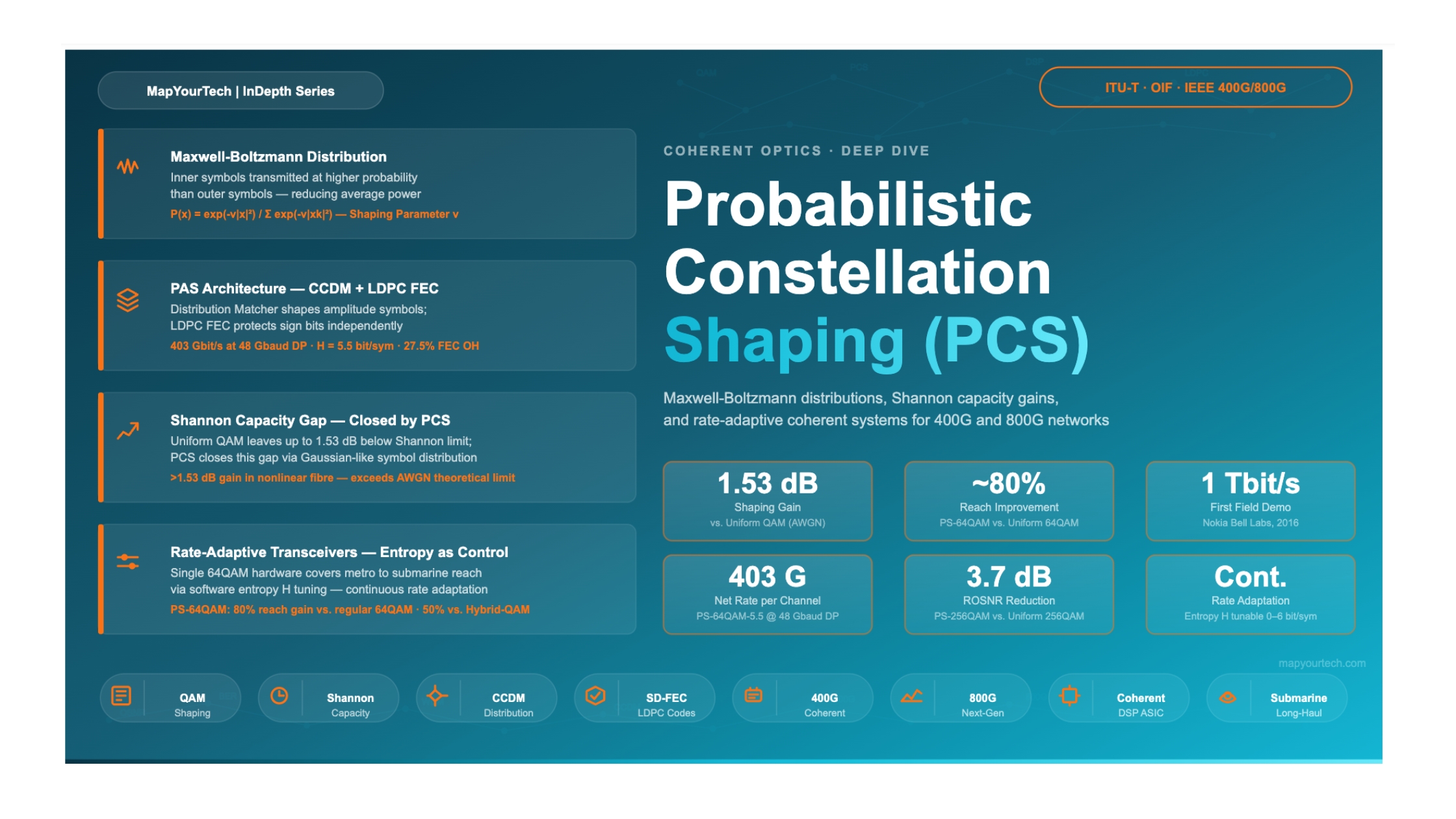

Probabilistic Constellation Shaping (PCS) in Modern Coherent Systems
How non-uniform symbol probabilities close the gap to the Shannon limit, enable rate-adaptive transceivers, and power the next generation of 400G and 800G optical networks
- Introduction
- The Problem with Uniform QAM
- Fundamental Principles of PCS
- The Maxwell-Boltzmann Distribution and Shannon Capacity Gain
- The Probabilistic Amplitude Shaping (PAS) Architecture
- Rate-Adaptive Transceivers with PCS
- Performance Analysis — PCS vs. Uniform QAM
- PCS vs. Hybrid-QAM — A Comparative Look
- Practical Deployment — 400G and 800G Systems
- Submarine and Long-Haul Applications
- Challenges and Implementation Considerations
- Future Directions
- Conclusion
- Glossary
- References
Introduction
Modern coherent optical networks operate under relentless pressure: traffic demands double roughly every two years, yet the physical capacity of deployed fiber — constrained by the Shannon limit of the optical channel — is finite. For more than a decade, engineers met growing bandwidth needs by moving to higher-order modulation formats: from 100G DP-QPSK to 200G DP-8QAM, 400G DP-16QAM, and beyond. Each step up the ladder carries more bits per symbol but demands proportionally better optical signal-to-noise ratio (OSNR). At some point, a hard ceiling appears: the available OSNR cannot support yet another format increment, and reach collapses.
Probabilistic Constellation Shaping (PCS) emerged from information theory to break this ceiling. Rather than selecting a new modulation format, PCS restructures the statistical behaviour of an existing QAM constellation. Symbols near the origin of the constellation — lower amplitude, more noise-resilient — are transmitted with higher probability. Outer symbols are used sparingly. The resulting non-uniform distribution closely mimics a Gaussian distribution, which is the optimal input distribution for an AWGN channel. The system can therefore operate closer to the Shannon limit without a hardware format change.
The technology attracted wide attention in September 2016 when Nokia Bell Labs demonstrated 1 Tbit/s transmission over a 4-carrier superchannel in the German backbone network using probabilistically shaped constellations. Shortly after, Alcatel-Lucent announced 65 Tbit/s over 6,600 km in laboratory conditions using PCS. These milestones confirmed what theorists had long predicted: PCS was not an incremental improvement but a qualitative shift in how optical systems approach capacity limits.
Today, PCS is a standard feature in commercially deployed 400G transceivers, and its role is becoming central to 800G platforms. This article explains the theoretical basis, the practical implementation through the Probabilistic Amplitude Shaping (PAS) architecture, and the deployment patterns that have emerged in metro, long-haul, and submarine networks.
2. The Problem with Uniform QAM
2.1 How Traditional QAM Works
In a standard quadrature amplitude modulation (QAM) system, each symbol in the constellation is transmitted with equal probability. For 16QAM, all 16 constellation points have an identical probability of 1/16. For 64QAM, each of 64 points carries probability 1/64. Binary source data is mapped to constellation points in a systematic pattern — typically Gray coding — and the modulator drives all points with equal frequency.
This uniform approach is simple and works well when the signal-to-noise ratio exactly matches what the chosen format requires. The problem arises from a fundamental mismatch between what uniform QAM sends and what the AWGN channel would ideally receive.
2.2 The Shannon-Capacity Gap
Claude Shannon proved in 1948 that the capacity of an AWGN channel is:
  C = B · log2(1 + SNR)    [ bits/s ]

  where:
    C   = channel capacity (bits/s)
    B   = bandwidth (Hz)
    SNR = signal-to-noise ratio (linear)
The capacity-achieving input distribution for the AWGN channel is Gaussian — not uniform.
Uniform QAM imposes a fixed, square lattice with equal symbol probabilities. This creates a "shaping gap" of up to 1.53 dB compared to a Gaussian-distributed input at the same average power.
In other words, a system using uniform 16QAM cannot reach the theoretical Shannon capacity for its SNR operating point — not because of a hardware limitation, but because of the statistical structure of the transmitted symbols. The 1.53 dB shaping gap is a theoretical upper bound; in practice, the achievable gain depends on channel conditions, FEC overhead, and the degree of shaping applied.
2.3 The Coarse Granularity Problem
Standard QAM formats also suffer from coarse granularity. Moving from 16QAM (4 bits/symbol) to 32QAM (5 bits/symbol) to 64QAM (6 bits/symbol) means spectral efficiency jumps in 1-bit integer steps. Each step is paired with a significant increase in required OSNR, meaning there is no way to trade off just a little extra spectral efficiency against a modest OSNR penalty. A 400G system optimised for 2,000 km reach using DP-16QAM cannot be incrementally pushed to 1,800 km at slightly higher capacity — it must commit to DP-32QAM or DP-64QAM and accept the associated reach penalty.
Read the Full Analysis with Premium
The remaining 88% of this article — the design numbers, trade-offs and field guidance — is part of MapYourTech Premium, along with the full premium library, courses and professional tools.



Course Title
Course description and key highlights