

Generic selectors
Exact matches only
Search in title
Search in content
Post Type Selectors
Articles
lp_course
lp_lesson
Back
HomeAnalysisSpectral Hole Burning in EDFAs
Spectral Hole Burning in EDFAs

Spectral Hole Burning in EDFAs

Last Updated: April 2, 2026
2 min read
97
Spectral Hole Burning in EDFAs: Mechanism and Compensation
Deep Dive · Optical Amplification

Spectral Hole Burning in EDFAs

Mechanism, Non-Uniform Gain Impact, and Compensation Strategies in Dense WDM Systems

C-Band & L-Band Amplifiers DWDM Systems Gain Equalization Submarine & Terrestrial

Summary

Spectral Hole Burning (SHB) is a gain saturation phenomenon unique to erbium-doped fiber amplifiers (EDFAs) in which a strong optical signal at a specific wavelength locally depletes the population inversion of erbium ions in its immediate spectral neighborhood, creating a localized reduction — or "hole" — in the amplifier's gain spectrum. Unlike homogeneous gain saturation, which reduces gain uniformly across the entire bandwidth, SHB is inherently wavelength-selective because erbium ions in a silica host exhibit inhomogeneous broadening due to the variation in their local crystal field environments.

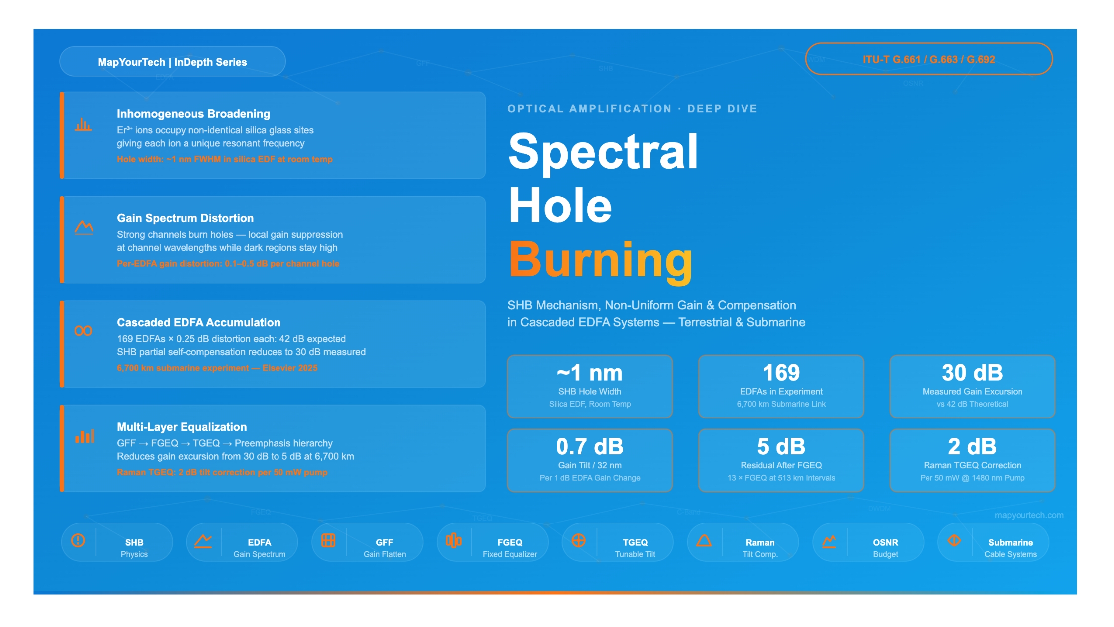
In partially loaded or unequally powered WDM systems, SHB causes stronger channels to suppress gain at their own wavelength and adjacent channels, while unoccupied or weaker portions of the spectrum retain higher gain. This creates progressive channel power divergence as signals cascade through hundreds of amplifiers in long-haul and submarine links. In a 6,700 km submarine link composed of 169 EDFAs, laboratory measurements have confirmed cumulated gain excursion reaching 30 dB when SHB is present — compared to a theoretically expected 42 dB without SHB, meaning SHB actually provides partial self-compensation.

Effective compensation strategies span passive approaches (gain-flattening filters, fixed gain equalizers, preemphasis), active approaches (tunable gain equalizers, automatic gain control), and hybrid Raman amplification used as a spectral tilt compensator. This article examines the physics, quantitative impact, system design implications, and practical mitigation of SHB in modern optical networks.

~1 nm Typical SHB hole width in silica EDF
0.25 dB Typical per-EDFA gain distortion (submarine)
30 dB measured vs 42 dB expected gain excursion at 6,700 km
0.7 dB Gain tilt per 32 nm per 1 dB gain change (EDFA)
<0.5 dB Target SNR degradation from gain non-uniformity
Section 1

Introduction and Background

The Erbium-Doped Fiber Amplifier (EDFA) transformed optical communications when it became commercially available in the early 1990s. By amplifying signals directly in the optical domain, it eliminated the need for electrical regeneration and enabled multi-span, multi-wavelength transmission over thousands of kilometers. The EDFA uses a silica fiber doped with trivalent erbium ions (Er³⁺) as its gain medium, pumped at either 980 nm or 1480 nm to achieve population inversion in the 1530–1565 nm C-band and 1570–1610 nm L-band.

As Dense Wavelength Division Multiplexing (DWDM) systems evolved to carry 32, 64, 80, and now more than 100 channels simultaneously, the interplay between multiple co-propagating channels and the amplifier gain medium became increasingly critical. One phenomenon that engineers encountered early in long-haul DWDM deployments was that channels at certain wavelengths were amplified more than others — and that this non-uniformity was not simply a property of the static EDFA gain shape. Instead, the gain spectrum changed dynamically depending on which channels were loaded, at what power levels, and how the load distribution changed over time.

This channel-dependent, dynamic gain non-uniformity has two root causes: the intrinsic wavelength-dependent gain shape of the EDFA (addressed with Gain-Flattening Filters, or GFFs) and Spectral Hole Burning — a subtler, physics-driven saturation phenomenon that acts at the level of individual erbium ion sub-populations. Understanding SHB requires understanding how erbium ions interact with their host silica matrix and why the gain medium does not behave as a perfectly homogeneous ensemble.

This article covers SHB from first principles through practical system impact and compensation, targeting engineers who design, operate, or optimize WDM transmission systems — from metro coherent links to transoceanic submarine cables.

Section 2

Fundamental Principles of EDFA Gain and the Origin of SHB

2.1 The Erbium Three-Level System

Erbium amplification is a three-level process. When pump photons at 980 nm are absorbed, Er³⁺ ions are excited from the ground state (4I15/2) to the short-lived pump band (4I11/2). They decay rapidly — in under one microsecond — via non-radiative relaxation to the metastable upper laser level (4I13/2), where they reside for a fluorescence lifetime of approximately 10 milliseconds. Signal photons in the 1530–1565 nm range stimulate the transition from 4I13/2 back to the ground state, releasing a coherent photon at the same wavelength — this is the amplification mechanism.

The gain G of an EDFA can be expressed as:

G = exp(σe × N2 × L)

Where:
  σe  = emission cross-section of Er³⁺ at the signal wavelength (m²)
  N2  = population density of erbium ions in the excited state (m⁻³)
  L   = length of the erbium-doped fiber section (m)

The noise figure F is given by:
  F  2 × nsp

  nsp = spontaneous emission factor (population inversion factor)
       = N2 / (N2 - N1)

Ideal fully-inverted EDFA: nsp ≈ 1 → F ≈ 2 (3 dB noise figure)
Practical EDFAs: F typically 4–6 dB depending on design and operating point

2.2 Homogeneous vs. Inhomogeneous Broadening

The gain bandwidth of an EDFA is not monochromatic but spans roughly 35 nm in the C-band and a similar range in the L-band. This broadening arises from two distinct physical mechanisms:

Homogeneous broadening means every erbium ion has the same gain lineshape — broadened by the Stark effect and phonon interactions. When any one of these identical ions is saturated by a strong signal, every ion in the ensemble contributes equally to gain reduction across the entire bandwidth. Homogeneous saturation is uniform: a strong signal at 1545 nm reduces the gain for all wavelengths proportionally.

Inhomogeneous broadening means erbium ions in a silica host do not all see the same local crystal field environment. The random nature of the silica glass network means that different Er³⁺ ions occupy different local sites — varying coordination geometries, local strain fields, and neighbor ion compositions. Each local site slightly shifts the Stark sub-level energies of the erbium ion, giving each ion a slightly different resonant transition frequency. The observed gain spectrum is therefore the convolution of many slightly shifted individual ion lineshapes.

Key Physical Insight

Because erbium ions in silica glass occupy non-identical local sites (inhomogeneous broadening), a strong optical signal can deplete the population inversion of the sub-population of ions resonant at its wavelength without equally depleting ions resonant at distant wavelengths. This localized population depletion creates a "hole" — a localized gain reduction — centered at the strong signal's wavelength. This is Spectral Hole Burning.

2.3 The SHB Mechanism in Detail

When a high-power signal at wavelength λs propagates through an EDFA, it preferentially stimulates emission from the subset of erbium ions whose resonant transition frequency most closely matches λs. These ions transition from the excited state to the ground state faster than they can be replenished by pump absorption and relaxation from the pump band. The result is a localized depletion of population inversion — specifically among the ions most resonant with λs.

Since gain at wavelength λ is proportional to the density of excited ions resonant at λ, this localized depletion creates a dip in the gain spectrum centered at λs. The width of this dip (the "hole") is determined by the homogeneous linewidth of the individual erbium ion sub-populations, which in silica fiber at room temperature is approximately 1 nm (125 GHz). The depth of the hole increases with signal power and decreases with increasing pump power (which tends to refill the depleted states).

The SHB gain perturbation at wavelength λ due to a saturating signal at λs can be approximated as:

ΔGSHB(λ, λs) = -ASHB × Ps × Lh(λ - λs)

Where:
  ASHB  = SHB coefficient (scales with inhomogeneous fraction of broadening)
  Ps   = power of the saturating signal at λs
  Lh   = homogeneous lineshape function (Lorentzian, ~1 nm FWHM in silica EDF)

In a WDM system with N channels, the total SHB perturbation at wavelength λ is:
  ΔGtotal(λ) = Σ ΔGSHB(λ, λn)   for n = 1 to N

Note: in practice, the exact ASHB depends on the specific EDF composition,
Al co-doping concentration, and operating temperature.
Figure 1: Spectral Hole Burning in an EDFA — Gain Spectrum Before and After Strong Signal Loading Wavelength (nm) Gain (dB) 1525 1535 1545 1555 1565 1575 15 20 25 30 35 SHB hole @ 1535 nm Deepest hole (highest-power ch.) SHB hole @ 1555 nm Peak ~1530 nm 2nd peak ~1553 nm Local dip ~1540 nm Natural EDFA gain rolloff (not SHB — same on both curves) Note: Hole depths are exaggerated for visual clarity. Actual SHB gain depression is 0.1–0.5 dB per EDFA per channel. Flat-loaded EDFA gain — characteristic double-hump C-band shape (without SHB) Gain with SHB — narrow local depressions at loaded channel wavelengths (~1 nm FWHM each) What Is Spectral Hole Burning? Strong channels deplete the excited-state population of Er³⁺ ions resonant at their wavelength. Inhomogeneous broadening in silica EDF localizes this depletion to a narrow spectral hole (≈1 nm FWHM). Hole depth proportional to channel power System Impact in WDM Loaded channels suppress their own gain; unloaded spectral regions retain higher gain. Over 100s of cascaded EDFAs, this causes significant inter-channel power spread. SHB partially self-limits cumulative tilt! Key Numerical Values Hole width (silica EDF): ~1 nm FWHM Hole depth: 0.1–0.5 dB per EDFA (typical) Significant accumulation: >100 cascaded spans Reference: 169 EDFAs, 6,700 km experiment Al-doped EDF shows stronger SHB than standard silica EDF (higher inhom. fraction) Depths in diagram exaggerated for clarity
Figure 1: C-band EDFA gain spectrum showing the characteristic double-hump shape (unloaded reference, blue dashed) and the effect of Spectral Hole Burning (red). Strong channels at 1535, 1545, and 1555 nm create narrow localized gain depressions (~1 nm FWHM). Actual hole depths are 0.1–0.5 dB per EDFA; depths are exaggerated here for visual clarity. The deepest hole corresponds to the highest-power channel, not a fixed wavelength.
Premium Article — Free 21% Preview

Read the Full Analysis with Premium

The remaining 79% of this article — the design numbers, trade-offs and field guidance — is part of MapYourTech Premium, along with the full premium library, courses and professional tools.


Instant access · Cancel anytime · 48-hour trial available
Sanjay Yadav

Optical Communications & Network Automation Expert | Author of 3 Books for Optical Engineers | Founder, MapYourTech

Optical networking engineer with nearly two decades of experience across DWDM, OTN, coherent optics, submarine systems, and cloud infrastructure. Founder of MapYourTech.

Follow on LinkedIn

You May Also Like

52 min read 12 0 Like The Submarine Cable Stack: Open Cables, GSNR, SDM and Power Skip to main content...
  • Free
  • July 10, 2026
32 min read 10 0 Like Coherent DSP Architecture: From ADC Samples to Client Bits MAPYOURTECH | COHERENT OPTICS DEEP...
  • Free
  • July 10, 2026
42 min read 14 0 Like Building an Optical NOC Dashboard with OpenConfig Telemetry Skip to main content MapYourTech |...
  • Free
  • July 10, 2026

Course Title

Course description and key highlights

Course Content

Course Details
